Table of Contents
Advertisement
Available languages
Available languages
Advertisement
Chapters
Table of Contents

Subscribe to Our Youtube Channel
Related Manuals for Phonic IS16v1


Summary of Contents for Phonic IS16v1
- Page 1 IS16 User's Manual Manual del Usuario...
- Page 2 IS16 Intuitive 16-Channel 8-Bus Digital Mixing console Consola de Mezcla Digital Intuitivo 16-Canales 8 Buses ENGLISH ........I ESPAÑOL .
-
Page 3: Table Of Contents
Networking ............................29 Troubleshooting ............................30 How Do I...? ............................31 FireWire + USB Operation....................32 Presets............................34 Digital Effect Table..........................41 Specifications............................43 Appendix Application..............................1 Dimensions ..............................3 Block Diagram ..............................4 Phonic preserves the right to improve or alter any information within this document without prior notice IS16... -
Page 4: Important Safety Instructions
IMPORTANT SAFETY INSTRUCTIONS The apparatus shall not be exposed to dripping or splashing and that no objects with liquids, such as vases, shall be placed on the apparatus. The MAINS plug is used as the disconnect device, the disconnect device shall remain readily operable. -
Page 5: Part One: Overview
Congratulations on your purchase of the IS16 digital mixer, • Audio Interface compatible with Windows XP, Windows the first full-digital mixing console from Phonic. With ultra low- Vista, Windows 7, Windows 8 and Mac OSX operating systems noise circuitry, including high quality, low-loss analog to digital • Wireless operation through Wi-Fi connection and Ethernet... -
Page 6: Digital Synchronization
Digital Synchronization LPF – Low Pass Filter – a low pass filter will cut all audio signals above a particular user-defined frequency, allowing low frequency sounds to pass through. This is significantly useful when using A word clock is provided to sync external digital devices, such as subwoofer speakers on particular outputs. DAT player. A master clock (e.g. Aardsync) is highly recommended, which maintains the word clock on a network. Please make sure Low Shelf Filter – the low shelf reduces or increases the level of to use only 75-ohm BNC cables for proper transmission of the audio signals below a particular frequency selected by the user. word clock signal. -
Page 7: Analog Controls And Settings
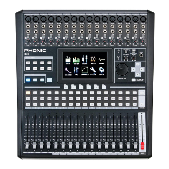
Analog Controls and Settings Channel Strips Analog Input Section 12. Select Button This button allows you to select the current channel. The channel XLR Mic Inputs is selected (whether it’s the input channel or the corresponding These XLR microphone inputs can be used in AUX, Group or Multi mix) will depend on your layer settings. The conjunction with a wide range of microphones, Main channel strip also features a select button, allowing users to such as professional condenser, dynamic adjust the properties of the Main mix. The select button will light or ribbon microphones, with standard XLR up when the corresponding channel is selected. -
Page 8: Display
SD Card and selecting the appropriate Firmware installed for this to be possible, however. update option in the Setup menu of the GUI. For the latest firmware, log on to www.phonic.com. 32. AES/EBU In & Out These connectors accept and send digital signals from AES/EBU enabled devices. The AES/EBU input can be assigned to the Main mix by pushing the AES/EBU button within the GUI software, while the main signal will be sent to the AES/EBU output. -
Page 9: Rack-Mounting Kit
Rack-mounting Kit 34. VGA Connector This VGA connector is available for customers to connect external 1. Remove the IS16’s side-panels by unscrewing the six computer monitors to their IS16. This will allow you to view the screws holding them in place. IS16’s user interface on a large screen. Customers can enter 2. - Page 10 Installing the Optional mREC Expansion Card 1. First ensure all power is off on your IS16 mixer and the power cable is disconnected. 2. Remove the included 16x16 FireWire / USB card on the IS16 by unscrewing the two support screws. 3.
-
Page 11: Part Three: Navigating And Selecting
PART THREE: NAVIGATING AND SELECTING Operation of the IS16 is made easy through the use of the full color touch screen. When first activated, the main menu of the IS16 will appear and users can jump directly to any particular function by touching the appropriate onscreen icon. Start-up The IS16 takes around two minutes to start up. The first screen users will see on the display is a red Phonic logo with a blue status bar indicating the status of the start up process. After this is done, the display will show the status of the DSP check. Power-On Self Test As soon as you turn on IS16, its central processing unit begins to carry out the programming instructions contained in the basic input/output system. The CPU is responsible for the following system and diagnostic functions: • Loading software • Performing initial hardware DSP checks If you see any error codes pop up during the testing phase, please turn off the unit and remove the power supply. Wait a minute, then replace the power supply and restart. This could rectify the problem. If the problem persists, however, please perform a system restore. When turning the system on you will be prompted to recall the settings from your previous session. You can opt to recall the last session’s settings or select no to revert back to default settings. User Interface IS16... -
Page 12: Touch Screen
Touch Screen The touch screen is used for accessing a number of different functions, menus, settings, tabs and so forth. Menus: To access any of the functions on the above menu, simply touch the corresponding onscreen icon. Users can also use the directional controls and ENTER button on the face of the mixer. Virtual Controls: To adjust virtual rotary controls and level faders, first select the appropriate control icon on screen. You can then use the IS16’s large jog wheel to increase and decrease the levels. Virtual faders cannot be adjusted by sliding a stylus up and down on screen. This helps avoid sudden and accidental alteration of signal levels. To turn on channels, solos, and so forth, simply push the onscreen icons. Header and Footer Header In the function header, users can jump directly to any of IS16’s functions by simply touching the appropriate icon. The icons are self- explanatory, but don’t worry if you can’t quite make out each and every one; it’ll be clear before too long. The icons listed above are, from left to right, View, Meter, Fader, Patch, Delay, Effect, EQ, Dynamics, Utility and Setup. To return to the main menu, simply touch the screen around the top left-hand corner (where the function title is displayed). When a name is set for a channel, this will also be displayed within the header bar. Footer The function footer features up and down arrows that allow users to scroll through the various functions (listed on the header), as well as brightness control to adjust the overall brightness of the LCD display. The tabs can be used to see further options on functions that offer multiple pages. The final icon, what looks like 2 level meters, is used to activate a peak hold on all meters. When the peak hold is active, a small red indicator will remain on all level meters to indicate the peak position of the meter. IMPORTANT: You may see a small yellow or red dot beside the brightness icon in the footer section. - Page 13 Saving, Loading and Deleting Presets/Scenes In the Effect, Equalizer, Dynamic Processor and Scenes functions, the above bar will allow users to save, load, delete and reset the settings for that particular function. Preset: Users are able to load one of the factory presets. For a list of available presets for each function, please see the Preset Tables at the end of this manual. Save: Push the Save button to save the current settings of the function you’re currently using. If in the Utility > Scenes menu, users will be saving the settings of all of the selected channels. Users can save their settings to the IS16’s onboard memory. When the save function is selected, users can select the keyboard icon to bring up the virtual keyboard and enter a name for their file. Naturally, ’OK’ should be selected to confirm. Load: Select Load to load any of your previously saved settings or scenes (as the case may be). Delete: Users can select Delete to delete any of their saved files from the IS16’s memory. Reset: Pushing reset will return all settings on the currently selected function to their default values. Initialize: Selecting the initialize button (found in the Utility menu) allows users to reinitialize the IS16 while still retaining all settings. Be sure to initialize your unit after performing a firmware update. View The view function will give users an overview of channel properties, from the level and panning of signals, to dynamic processes, EQs and other properties. When the View menu is activated, users can select the channel they wish to view/adjust the properties of using either...
- Page 14 1.1.1 Off / On Button 1.1.14 Dynamic Processor Selection and On/Off Buttons This button will turn the currently selected channel on and off. With these buttons, users can activate and deactivate the corresponding dynamic processor functions, as well as view their 1.1.2 Solo Button properties on the Master Dynamic Processor Display (located to This will activate the solo function on the currently selected the left of these buttons). Available Dynamic Processors are: Gate, channel. When a channel is soloed, the signal will be diverted...
- Page 15 AUX / Group Tab This section explains the following AUX and Group operations: • Configuring AUX Sends • Configuring AUX/Group Masters AUX and Group Masters can be fed by any input channels, and can be assigned to MULTI outputs 1 to 8. The Group mixes can also be assigned to the Main stereo mix. IS16...
- Page 16 1.2.1 Channel Send Rotary Controls 1.2.9 EFX Assign Buttons (not pictured) Each of these level controls will determine the level of signal from Push either of these buttons to assign the output from the the corresponding input channel that will be sent to the currently corresponding EFX processor to the currently selected AUX or selected AUX mix.
- Page 17 Control Room Tab 1.3.1 Global Buttons 1.3.4 Solo Source Buttons These buttons allow users to turn all of the Control Room source Push any of these buttons to select whether the signal taken from signals to either AFL or PFLs. the appropriate channel inputs, AUXs or Groups, Main or EFX processor will be pre-fader listens (PFLs) or after-fader listens 1.3.2 Solo Safe Button...
- Page 18 Main / Multi Tab 1.4.1 On / Off Button 1.4.12 Dynamic Processor On / Off and Display This button will turn the currently selected output channel on Pushing this button turns the dynamic processor on and off. The and off. display that accompanies it gives a quick visual representation of 1.4.2 Main Mono/Stereo Select...
- Page 19 2. Metering Channel Tab This tab allows users to view the levels of all input channels, as well as the main stereo mix. Users can view peak levels by taking note of the red mark at the top of the meters. The meters can be changed between pre-fader and post-fader meters by pushing the pre/post buttons located below the meters. The input channels’ meters can be adjusted to display the input signal (post-gain, pre-on/off), pre-fader (post-gain, post-on/off) and post-fader (post-fader, -EQ, -dynamics, -delay). You can also view the status of dynamic processors assigned to the corresponding channels by viewing this window. Each the expander, gate, compressor and limiter have their own indicator for each channel as well as the main output. A red light indicates that the corresponding dynamic process is clipping; a blue light indicates that the corresponding dynamic process is turned on, and; a yellow light indicates that the corresponding dynamic process is currently active (ie. the set threshold has been passed). AUX / Group Tab The AUX/Group meter page allows users to view the output levels of each of these mixes, as well as the main mix – all on a single page. A small red mark will hold high peaks for a short time. Users are able to adjust these meters between pre- and post-fader meters by pushing the Pre/Post Meter buttons. The post-fader signal displayed is post-fader, -equalizer, -dynamics and -delay.
- Page 20 Meter / Fader Tab The Meter section in the Meter / Fader Tab allows users to easily adjust levels of each input channel and AUX and Group mix, as well as the main mix. Found directly next to each of these virtual faders is a level meter. Level meters can be changed between pre and post by pushing the appropriate pre/post buttons on the right-hand side of the display. The input channels’ meters can be adjusted to display the input signal (post-gain, pre-on/off), pre-fader (post-gain, post-on/off) and post-fader (post-fader, -EQ, -dynamics, -delay). If any two input channels are paired (achieved through the Setup menu) these will be indicated as such by a small chain image located between the two channels’ controls/meters. When two channels are paired this is indicated in the menu FADER by a red triangle in the upper right corner of both channels, and the “slave” channel is grey. Multi Tab The Multi tab of the meter function displays the input and output signals of the Multi signals, EFX signals, the AES/EBU signals, and Control Room output. The menu also provides a number of different controls to users. All Multi outputs can be turned on and off and have their levels adjusted. The main stereo mix can have its level adjusted. The EFX signals can be turned on and off and have their output levels adjusted. The Control Room trim can be adjusted. The trim can be adjusted on the AES/EBU input, which can also be turned on and off within this menu. If no digital device is connected to the input, users will not be able to activate the AES/EBU inputs.
- Page 21 3. Faders 3.2 AUX & Group Tabs The AUX and Group tabs in the Fader function are, for all intents 3.1 Channel Tab and purposes, the same. This section will combine the two. 3.1.1 Channel Select 3.2.1 Channel Select Select this button to choose the channels that are displayed on Push this button to bring up the range of channels you wish to screen. Users can select channels 1 through 4, 5 through 8, 9 view the properties of.
- Page 22 3.3 Main Tab 3.3.1 Main Fader This fader will adjust the final output level of the Main mix. 3.3.2 Level Meter This stereo level meter shows the final output level of the Main. By pushing the Meter Pre/Post button that is included next to this meter, users are able to also view the pre-fader signal. 3.3.3 On/Off Button This button will activate and deactivate the Main mix. When set to off, the Main mix will not be sent through the Main output jacks. 3.3.4 Stereo / Mono Button Pushing this button will adjust the main output signal between a stereo signal and a mono signal. This effectively bypasses the pan controls on all channels and combines stereo signals. 3.3.5 AES/EBU Level Fader This fader will adjust the incoming signal level from any external AES/EBU-enabled device currently connected to the appropriate XLR AES/EBU inputs on the rear of the IS16.
- Page 23 4. Patch Each of tabs in the Patch function provides the same options, allowing for users to set the processing order of the equalizer, dynamic processor and delay functions for each individual signal. Users can also activate and deactivate any of these individual processes using the accompanying buttons. The tabs allow users to view channels 1 through 8, 9 through 16, all multi outputs, or the main output. IS16...
- Page 24 1 second. The mix can be adjusted between 0% (no effect) to 100% (completely saturated). Feedback gain can be adjusted between 0 and 99%. Multi and Main outputs can only have their delay time adjusted. In addition to the delay itself, you are able to adjust both the scale used and the current ambient temperature. Users are able to adjust the delay scale between milliseconds, meters or feet. Adjusting the delay in meters and feet helps users to overcome the distance between the main stage and rear speakers in larger setups. When adjusting the delay by meter or feet, Phonic suggests using the distance between the main stage and the speakers. Entering an accurate temperature will allow the IS16 to calculate the best delay time based on the distance between the stage and speakers. IS16...
- Page 25 Effect Any of the IS16’s input channels or AUX mixes can be assigned to the built in digital effect processor. To apply an effect to any particular channel, select the channel within the EFX menu’s input selection section. To apply an effect to a few different channels (or a mix of a few different channels) simply send the channel(s) to an AUX mix and apply the desired effect to that mix. The output of the EFX processor can then be selected between the Main, Groups and Multi. The effects menu also offers access to Networking features. EFX 1 & 2 6.1.1 Input Selection 6.1.5 On/Off Button Here users can select which signals they wish to apply the digital This button will turn the effect processor on and off. When set to effect to.
- Page 26 WPA2 or WEP. By setting authentication to of the IS16 will be essentially disabled. Users can select Wifi or “Open” on your router you are essentially opening your network Ethernet when wanting to use either of these protocols. When Wifi up to anybody with a Wifi device. Phonic recommends setting is selected the USB Wifi dongle must be connected to the Wifi your router to one of the available authentication types to ensure port on the rear of the IS16.
- Page 27 Equalizer The IS16 provides a 4-band parametric equalizer on each input channel, Multi 1 to 8 outputs and Main Mix. All parameters are adjusted using the data encoders or touch-screen. Users are able to select a boost or cut of up to 18 dB on frequencies between 20 Hz and 20kHz. A 31-band equalizer is also available on the Main output, and can be selected by entering the Patch menu and changing the Order settings to include the GEQ instead of the EQ.The Q of these signals can also be adjusted to give a wider or narrower band, as necessary. Signal Source Here users can select which channel’s EQ to set. An equalizer can be applied to any of the input channels, any of the Multi outputs and the main mix. EQ On/Off Button This button can turn the Equalizer for the currently selected channel on and off.
- Page 28 8. Dynamics The IS16 provides a built-in Gate, Expander, Compressor and Limiter on each input Channel, Multi 1 to 8 outputs and Main Mix. Dynamics are not limited by DSP resources, and can be configured as pre- or post-EQ/Delay for each channel. All built-in dynamics parameters are adjusted using the touch-screen and onboard controls. A noise Gate is a dynamic process that turns off or significantly attenuates the audio signal passing through it when the signal level falls below a user adjustable threshold. An Expander helps to make troublesome background noise (such as humming) inaudible by reducing signals with low amplitudes. A Compressor reduces signals over a user-defined threshold by a user-defined amount/ratio. Limiters work just as Compressors do, with a ratio permanently set to infinity-to-1. To bypass the dynamics processor, simply push the ON/OFF button or press the “GATE”, “EXP”, “COMP” and “LIM” buttons to toggle the individual processes on and off. Each of the pages/tabs in the Dynamics menu is essentially the same, providing similar attributes for the individual processes. Channel Select Use this button and the subsequent menu to select the channel you wish to apply the dynamic effect to. Users can select from any of the input channels, any of the multi outputs, and the main stereo mix.
- Page 29 9. Utility Scene In the scene menu, users can select which channels they wish to save the current settings of. Select one or more of the available input channels, AUX channels, Group channels or the Main mix, and select Save. Users are also able to select and unselect all channels with the included buttons. The saved settings for each are: select, fader levels, on/off, panning, equalizer, dynamics, effects, AUX sends, delay and routing. Naming This function will allow users to assign names to each of the input channels and the multi outputs. Names can be up to 9 characters long and contain letters, numbers, parenthesis, dashes and underscores. Simply click the display window of the appropriate channel to bring up a digital keyboard. Users can use this to key in a name for the channel. This can be anything from the name of the instrument/input source, to the name of the person playing said instrument. For the Multi Outputs, users can – for example – enter the destination of the signal (the name of a performer monitoring the signal, recording device’s model number, and so on).
- Page 30 Generator / VGA Through the Signal Generator, users are able to send a Sine wave (100 Hz, 1 kHz or 10 kHz) or a pink noise signal to any of the AUX or group mixes, as well as the main mix if need be. The On/Off button allows users to turn the signal generator on and off, and the accompanying level control (virtual rotary control) will allow adjustment of the signal level. At the bottom of this screen, users can find two aspect ratio options for the monitor connected to the IS16’s VGA output. Users can select either full screen (4:3) or wide screen (16:9) mode depending on the aspect ratio of their monitor. To the right of the ASPECT RATIO selection the user can find options for the touch screen dimming. Users can select the time that it will take for the screen to go dim, or opt to disable the function all together. IS16...
- Page 31 Setup 10.1 Link/Pair 10.1.1 Link Mode Users are able to link the level controls of any of the input channels together using the Link Mode function. Users are able to link up to 4 groups of channels together, and each group is color-coded. The link groups are labelled A, B, C and D and are colored orange, green, purple and brown, respectively. If users link channels together, adjusting one fader within the link group will allow users to control all the others, while maintaining their relative level differences. 10.1.2 Channel Pair Activating pair mode on any combination of the channels will copy the fader settings and parameters from one channel to another. All odd-numbered channels can have their parameters copied over to the evenly numbered channels that succeed them (or vise-versa). The parameters copied do not include the invert phase or DAW functions. Paired channels’ linked parameters are: Select, On/Off, Panning, Equalizer, Dynamics, Effects and AUX Send On/Off.
- Page 32 10.2 Clock Source In the Clock Source tab of the Utility menu, users are able to select the clock source of the AES/EBU input and output. The clock source can be selected from Internal (with sampling rates of 44.1 kHz, 48 kHz, 88.2 kHz and 96 kHz), the digital device, or the Word Clock input/output. The selected Sampling Rate – or that set by the external device – is displayed at the bottom of this menu. The Enter button must be pushed to confirm new Clock Source settings. 10.3 LCD Calibration Select this tab to calibrate the IS16’s color touchscreen. When the LCD Calibration tab is selected, crosshairs will appear onscreen and users should select these one by one to calibrate the touchscreen. If the screen becomes uncalibrated for whatever reason, and the appropriate menu cannot be selected, users should use the IS16’s onboard controls to navigate the GUI and bring up the LCD Calibration function. If it becomes necessary to calibrate the screen, users can use the tab buttons, directional buttons and ENTER button on the IS16 to allow them to access the calibration function. IS16...
-
Page 33: System Restore
IS16 becomes impossible due to corruption of one or more of the DSPs, there is a relatively simply way to get it up and running again. First, visit www.phonic.com to download our IS16 System Restore Software. Place the software on a blank SD card. -
Page 34: Troubleshooting
Can’t save to external SD card o If the power still does not turn on, contact your nearest o Is the SD card write protected? Phonic dealer for service. o Ensure your card is either an SD or SDHC card. o Does the SD card have enough free space to save the data? -
Page 35: How Do I
How Do I…? …Add a delay to my guitar? Again, the delay is available in each channels’ View screen …Connect a monitor to the IS16? (although it also has its own independent menu). Users can turn You can connect any modern display device to the VGA connector the delay on here;... -
Page 36: Firewire + Usb Operation
After doing so, you should be able to connect both SOLO SAFE is active on a channel, the word SAFE will appear units in a daisy-chain and have them recognized by the Phonic within the solo button. Control Panel. - Page 37 Having two clock sources has the potential to cause undesireable Input Channels results to your audio, so it is best avoided. If the IS16 is the only piece of digital audio equipment attached to the computer, there is no reason this option should be changed. Users are also able to change between automatic and manual sampling rate settings.
-
Page 38: Presets
PRESETS Dynamic Presets Gate Program Range Hold Threshold Attack Release Default 125mS 6.3mS 400mS Gate 1 1.6Sec 12.5mS 2sec Gate 2 1.6Sec 12.5mS 2sec Gate 3 2.00Sec 6.3mS 400mS Expander Program Ratio Threshold Attack Release Default 2 : 1 50mSec 400mSec Expander 1 1.5:1 3.15mSec 63.0mSec... - Page 39 Bass Drum 2 PEAKING PEAKING PEAKING LPF +3.0 dB –3.0 dB +3.0 dB 82.3 399.1 2517.9 13041.1 — Snare Drum 1 PEAKING PEAKING PEAKING H.SHELF –0.5 dB 0.0 dB +2.0 dB +4.0 dB 132 Hz 1.00 kHz 3.15 kHz 5.00 kHz 0.35 —...
- Page 40 Syn. Bass 2 PEAKING PEAKING PEAKING H.SHELF +2.5 dB 0.0 dB +1.5 dB 0.0 dB 130.4 181.2 1181.6 12210.8 — Piano 1 L.SHELF PEAKING PEAKING H.SHELF –4.0 dB 0.0 dB +2.0 dB +4.0 dB 93.9 969.6 3990.5 7455.2 — — Piano 2 PEAKING PEAKING PEAKING...
- Page 41 Digital Effect Presets Reverb Room Default Reverb_ Early_ Gate Gate Hold Program Name LPF_Freq HPF_Freq Pre_Delay Hi_Ratio Density Level Time Delay Thresh Time Default 2.45s -70dB Preset Large Room 1.2s 23ms -70dB Preset Medium Room 1.0s 23ms Preset Small Room 5.6K 300ms Preset Live Room...
- Page 42 Chorus Chorus Default LFO_ Program Name LFO_Freq LFO_Type Depth Pre_Delay LPF_Freq Phase Default 0.2Hz 90degree Triangle Preset Chorus 0.2Hz 180degree Triangle Chorus 1 180degree Triangle Chorus 2 1.4Hz 90degree Triangle Chorus 3 2.2Hz 180degree Triangle Flanger Flanger Default LFO_ Program Name LFO_Freq LFO_Type...
- Page 43 Digital Effect Presets Room Default Name Reverb Pre_Delay Early_Delay Hi_Ratio Density Level Large Room 1.2s 23ms Medium Room 1.0s 23ms Small Room 5.6K 40ms Live Room 1.15s 21ms Bright Room 300ms Wood Room 2.24K 50ms Heavy Room 1.0s 10ms Opera Room 3.15 Hall Default Name Reverb...
- Page 44 Flanger Default Name Phase Type Depth Pre_Delay Flanger 180degree Triangle Phaser Default Name Type Depth Freq Stage_No Stage_No Phaser 19.95Hz Triangle 100% Vibrato Default Name Type Depth Freq Freq Vibrato 16.4Hz Triangle 100% 10Hz 10Hz Tremolo Default Name Type Depth Depth Tremolo 6.1Hz...
-
Page 45: Digital Effect Table
DIGITAL EFFECT TABLE Effect Parameter Range Description Reverb Room (Large Room, H.P.F. 20 Hz to 20 kHz Adjusts the high pass filter cut off frequency Medium Room, Small Room, L.P.F. 20 Hz to 20 kHz Adjusts the low pass filter cut off frequency Live Room, Bright Room, Rev Time 50 ms to 10 sec Adjusts the reverb time of the effect Wood Room, Heavy Room, Opera Room) Pre Delay 0 to 100 ms Adds a delay prior to the effect being applied Early Out 0 to 100%... - Page 46 Tap Delay Feedback 0 to 99% Adjusts the feedback gain of input signal Tap Button 1 ms to 5 sec Push twice to adjust the tap delay time 20 Hz to 20 kHz Adjusts the low pass filter frequency of the signal 20 Hz to 20 kHz Adjust the high pass filter frequency of the signal Chorus L.F.O. 0.1 to 20 Hz Low frequency oscillation Phase 0 to 180∘ Modulation phase adjustment Mode Type Sine / Triangle Determines the modulation waveform Depth...
-
Page 47: Specifications
SPECIFICATIONS Mic In : 16 x XLR Balanced (ch 1-16) Analog Inputs Line In : 16 x TRS Balanced jacks (Ch 1-16) Insert I/O 16 x Phone jacks (Unbalanced) 2TR IN Analog 2 x RCA (Unbalanced) 2 x XLR Balanced Stereo Output 2 x RCA (Unbalanced) Main Output 2 x XLR Balanced Control Room Output 2 x XLR Balanced Multi Outputs 8 x TRS Balanced AUX/Group Output 8 x TRS Balanced (Shared through Multi) Phones 1 x Stereo Phone jack (TRS Unbalanced) Digital I/O (AES/EBU) 2 x XLR Balanced Sampling Frequency 44.1 kHz, 48 kHz, 88.2 kHz, 96 kHz (40-Bit Floating Point Mixing) Signal Delay (CH INPUT to STEREO OUT) Fs=48 kHz <1.2ms, Fs=96 kHz <0.6ms Faders 17 x 100mm motorized faders... -
Page 48: Service And Repair
Phonic, at its option, shall repair or replace the defective unit covered by this warranty. Please retain the dated sales receipt as evidence of the date of purchase. - Page 49 ¿Cómo hacer…?.............................28 Tarjeta de Expansión mREC Opcional....................30 Presets..........................32 Tabla De Effectos Digitales......................39 Características..........................41 Apéndice Aplicación......................1 Dimenciones ..........................3 DIAGRAMA DE BLOQUES..................4 Phonic se reserva el derecho de mejorar o alterar cualquier información provista dentro de este documento sin previo aviso.
-
Page 51: Primera Parte: Prespectiva
PCM WAV de 16-canales y un Felicitaciones en la compra de la mezcladora digital IS16, la FireWire/USB 2.0 multi-pista interface grabación audio; primera consola de mezcla digital de Phonic. Con circuito de USB 3.0 flash drives compatible ruido-ultra bajo, incluyendo alta calidad, poca perdida de análoga a convertidores digital. El IS16 ofrece todo lo que una mezcladora •... -
Page 52: Sincronización Digital
Sincronización Digital Limitador – funciona tal como un compressor hace, no obstante con una relación señal de entrada a salida permanente configurada a infinitivo a 1. Un word clock es ofrecido para sincronizar dispositivos digitales externos, tales como DAT player. Un master clock (ej. Aardsync) LPF – Low Pass Filter – un filtro de paso bajo cortará toda es altamente recomendado, que mantiene el word clock en una señal de audio sobre una frecuencia particular usuario definible, red. -
Page 53: Controles Y Configuraciones Análogas
Controles y Configuraciones Análogas 11. Control Room / 2TR In Botón Active este botón permitirá a los usuarios a monitorear las entradas Sección de Entrada Análoga RCA 2TR mediante las salidas de Control Room. Al liberarlo, los usuarios podrán monitorear su señal central estéreo o señales Entradas XLR Mic Solo. Estas entradas XLR de micrófono pueden ser usadas en conjunto con una amplia Canal de Tiras gama de micrófonos, tales como micrófonos 12. -
Page 54: Pantalla
IS16. Estas actualizaciones son realizadas en insertar una tarjeta SD y seleccionar la actualización apropiada del Firmware o programa opciones en el menú de Setup de GUI. Para los más recientes firmwares, visite www.phonic.com. 32. Entrada & Salida AES/EBU Estos conectores aceptan y envía señales digitales desde dispositivos disponibles AES/EBU. La entrada AES/EBU puede Sección de Control ser asignada a la mezcla Central al presionar el botón AES/EBU... -
Page 55: Juego Rack De Montaje
Juego Rack de montaje 34. Conector VGA Este conector VGA está disponible para los consumidores en 1. 1. Remover los paneles de lado del IS16, destornillando los conectar monitores de computadora externos a su IS16. Esto le seis tornillos que lo sostiene en lugar. permite en visualizar el interface IS16 del usuario en una pantalla 2. 2. Adjunte las alas de rack y atorníllelas en lugar. -
Page 56: Instalación De La Opcional Tarjeta De Expansión Firewire + Usb
Instalación de la opcional tarjeta de expansión FireWire + USB 1. Primero, asegure que la potencia de su mezcladora IS16 y cable de potencia esta desconectada. 2. Remover la tarjeta 16x16 FireWire / USB incluido en la tapa protectora posterior del IS16 al destornillar los dos tornillos de suporte. 3. Remover la cinta del cable ubicado dentro de la ranura de la tarjeta de expansión. 4. Conecte el cable de cinta a una conexión apropiada en la tarjeta de expansión. 5. Inserte la tarjeta de expansión dentro de la ranura para dicha tarjeta y atornille en lugar. IS16... -
Page 57: Tercera Parte: Navegando Y Seleccionando
TERCERA PARTE: NAVEGANDO Y SELECCIONANDO La fácil operación del IS16 es por medio de uso de la pantalla a color táctil. Al ser activado de primera, en el menú principal de la unidad del IS16 se activará y los usuarios podrán entrar directamente a cualquier función particular con solo tocar el icono apropiado de la pantalla. Comienzo El IS16 toma alrededor de dos minutos para comenzar. Lo primero que aparecerá al usuario en la pantalla será el logo rojo de Phonic con una barra azul indicando el estado del proceso de comienzo. Después de que este proceso esté finalizado, en la pantalla aparecerá el estado del chequeo DSP. Prueba de Activación Propia Al encender el IS16, el proceso central de la unidad comienza a ejecutar la programación de instrucciones conteniendo en el sistema... -
Page 58: Interface De Usuario
Interface de Usuario Pantalla Táctil La pantalla táctil es usada para accede un número de funciones diferentes, menús, configuraciones, tabs y más. Menús: Para acceder cualquiera de las funciones sobre el menú, simplemente toque el icono correspondiente en la pantalla. Los usuarios pueden usar los controles direccionales y botón ENTER. Controles Virtuales: Para ajustar virtualmente los controles giratorios y niveles de deslizador, primero seleccione el icono de control apropiado en la pantalla. Usted puede luego usar el jog Wheel grande del IS16 para incrementar y decaer los niveles. Los deslizadores virtuales no pueden ser ajustados en deslizarlos en pantalla desde arriba hasta abajo. Esto ayuda a prevenir accidentes de alternación repentina de niveles de señal. Activando los canales, solos y más, sencillamente presione los iconos en pantalla. Encabezado y Pie de Página Encabezado En la función de encabezado, los usuarios pueden ir directo a cualquiera de las funciones del IS16 con el simple toque en el icono apropiado. Los iconos están claramente visualizados, usted no tendrá cuestiones de no entenderlos. Los iconos listados están en orden de izquierda a derecha; View, Meter, Fader, Patch, Delay, Effect, EQ, Dynamics, Utility y Setup. Para volver al menú principal, solo necesita tocar en la parte de la esquina izquierda superior de la pantalla (donde los títulos de las funciones están mostrados). Cuando uno nombre está configurado para un canal, el mismo será mostrado en la barra de encabezado. Pie de Página La función de pie de página figura flechas de hacia arriba y abajo que permite al usuario en desplazarse en varias funciones (listadas en el encabezado), así como el control de iluminación para ajustar la iluminación de la pantalla LCD. El tab puede ser usado parea ver más opciones que ofrece las múltiples páginas. El icono final, con apariencia de 2 indicadores de nivel, es usado para activar el peak hold en todos los indicadores. Cuando dicho peak hold es activado, un indicador rojo pequeño estará presente activado en todos los niveles del indicador para mostrar la posición del peak en el indicador. - Page 59 Guardar, Cargar y Eliminar Pre-configuraciones/Escenas En las funciones de Efecto, Ecualizador, Procesador Dinámico y Escenas en la barra superior le permitirá guardar, cargar, eliminar y re- configurar configuraciones para función particular. Pre-configuraciones (Preset): Los usuarios están disponibles en cargar una del pre-configuración determinadas de fábrica. Para una lista de pre-configuraciones de cada función, favor versé en la Tabla de Pre-configuraciones al final de este manual. Guardar (Save): Presione el botón de Save para guardar la configuración actual de la función que usted está usando presentemente. Si en Utility > Scenes menú (Utilidad>menú de Escena), los usuarios estarán guardando las configuraciones de todos los canales selectos. Los usuarios también pueden guardar sus configuraciones en memoria a bordo del IS16. Guarde la función esta selecta, los usuarios pueden seleccionar el icono de teclado para llamar el teclado virtual e ingresar el nombre de su archivo. Evidentemente , un ¨OK¨ debe ser seleccionado para confirmar. Carga(Load): Seleccione carga para cargar cualquiera de las configuraciones previamente guardadas o escenas. Eliminar (Delete): Los usuarios pueden seleccionar Eliminar para cancelar cualquiera de sus archives guardados en la memoria del IS16. Re-iniciar (Reset): Presione re-iniciar para retornar todas las configuraciones a la funcionalidad presentes a los valores de fábrica predeterminado. Inicie (Initialize): Seleccione el botón de iniciar (localizado en el menú de Utilidad) permitiendo a los usuarios en re-iniciar el IS16 mientras aun manteniendo todas las configuraciones. Asegúrese de iniciar su unidad después de ejecutar la actualización del firmware.
- Page 60 Canal Tab 1.1.13 Procesador Máster Dinámico On/Off y Display 1.1.1 Botón Off / On Este botón activará y desactivará el Procesador Dinámico. Con Este botón activará y desactivará el canal presentemente selecto. el EQ, todos los procesadores dinámicos serán anulados si este Si el canal ya ha aplicado un soleo seguro, la palabra SAFE botón está inactivo. También como la función de EQ, el gráfico aparecerá...
- Page 61 Control Room Tab 1.2.1 Botones Global 1.2.4 Botón Solo Source (Fuente de Solo) Estos botones permiten a los usuarios en encender todas las Presione cualquiera de estos botones para seleccionar si la señal señales de fuente Control Room a cualquier AFL o PFL. es tomada desde entradas de canal apropiada, AUX o Grupos, Central o procesador EFX será pre-fader listen (siglas en ingles 1.2.2 Botón de Solo Safe PFL o monitoraje del nivel de una señal antes de un control de Presione el botón de Solo safe para seleccionar el asegurado volumen)-o after-fader listen (siglas en ingles AFL o monitoraje del...
- Page 62 Main / Multi Tab 1.3.1 Botón On / Off 1.3.12 Procesador Dinámico On / Off y Display Este botón activará y desactivará el canal de salida presente. Activando este botón encederá y apagará el procesador dinámico. 1.3.2 Selección Main Mono/Estéreo Esta pantalla que acompaña a una representación rápida visual Usando esta opción los usuarios podrán seleccionar si la mezcla del proceso dinámico presente.
- Page 63 a en centro y puede ser ajustado a izquierda o derecha si es necesario. Sin embargo, mezcla de Grupo son asignados a salidas Multi una vez limitadas a lo antes mencionando de impar en izquierdo y par en derecho. Mezclas de grupo paneado en la izquierda solo puede ser enviado fuera mediante las salidas de numeradas Multi impares, mientras el paneo derecho son enviados fuera en salida de número pares (como asignadas). 2. Medida Canal Tab Este tab permite a los usuarios en visualizar todos canales de entrada, así como la mezcla central estéreo. Pueden visualizar los niveles peak con tomar nota de las marcas rojas en la parte superior del indicador. El indicador puede cambiar entre pre-fader y post-fader son solo presionar los botones pre/post ubicados abajo del indicador. Los indicadores de las entradas de canales puede ser ajustada para visualizar la señal de entrada (post-gain, pre-on/off), pre-fader (post-gain, post-on/off) y post-fader (post-fader, EQ, Dynamics, delay). Usted también puede ver el estado del proceso dinámico asignado a los canales correspondiente s por la ventana de visualización. Cada expansor, compuerta, compresor y limitador tiene sus propios indicadores para cada canal así como la salida central. Una luz rojo indica que el proceso dinámico está desactivado, una luz azul significa que el proceso dinámico está activado y una luz amarilla indica que el proceso dinámico corriente está activa (ej. el umbral configurado ha sido pasado). AUX / Group Tab La página del indicador AUX/Grupo permite a los usuarios en visualizar los niveles de salida de cada una de estas mezclas, así como la mezcla central todo en una solo página. Una marca roja pequeña sostendrá el peak alto por un corto periodo de tiempo. Los usuarios tendrán disponibilidad de ajustar estos indicadores entre pre- y post-fader presionando los botones de Indicador Pre/Post. La señal post-...
- Page 64 Meter / Fader Tab La sección de Meter (Indicador) en Meter/Fader Tab permite a los usuarios en ajustar niveles de cada canal de entrada y AUX y mezcla de Grupo con facilidad, así como la mezcla central. Ubicado directo a cada lado de estos deslizadores virtuales es el indicador de nivel. Los indicadores de nivel pueden ser cambiados entre pre y post presionado los botones apropiados pre/post en el lado derecho de la pantalla. Los indicadores de entrada de canal puede ser ajustada (post-fader,-EQ,-dynámica,-delay). Si cualquiera de estos dos canales de entrada es emparejada (mediante el menú) estas estarán indicadas como tales por una imagen de pequeña cadena ubicada entre los dos canales de controles/meters.Cuando dos canales están emparejados esto se indica en el menú FADER por un triángulo rojo en la esquina superior derecha de ambos canales, y el canal “esclavo”es de color gris. Multi Tab La función de Multi tab del indicador muestra las señales de entrada y salidas de las Multi señales, señales EFX, señales AES/EBU y salida de Control Room. El menú también ofrece un número de diferentes controles a los usuarios. Todas las salidas de Multi pueden ser activadas y desactivadas y tienen sus propios niveles ajustados. La mezcla central estéreo puede tener su propio nivel ajustado. Las señales de EFX pueden ser activados y desactivados teniendo sus propias salidas de nivel ajustadas. El recorte o trim de Control Room puede ser ajustada. El trim puede ser ajustada en la entrada AES/EBU, puede ser activada y desactivada en este menú. Si no hay un dispositivo digital conectado a la entrada, los usuarios no podrán activar las entradas AES/EBU. Usted podrá ver el estado de los procesadores dinámicos asignado a multi salidas correspondientes por esta ventana de visualización. Cada expansor, compuerta, compresor y limitador tienen sus propios indicadores para cada multi salida. La luz roja indica que el proceso dinámico correspondiente está desactivado; una luz azul indica que dicho proceso está activado, y una luz amarilla indica que el proceso está activado (ej. la configuración del umbral ha sido pasado.) IS16...
- Page 65 3. Deslizadores (Faders) 3.2 AUX & Group Tabs La función del fader AUX y Group tabs para todas las propósitos 3.1 Canal Tab o intenciones, lo mismo. Esta sección será combinada en dos. 3.1.1 Selector de Canal 3.2.1 Selector de Canal Seleccione este botón para elegir los canales que están mostrados Presione este botón para llevar la gama de canales que usted en la pantalla. Los usuarios pueden seleccionar canales 1 al 4, 5 desea visualizar tales propiedades. Los usuarios pueden al 8, 9 al 12, o 13 al 16.
- Page 66 3.3 Tab Central 3.3.1 Deslizador Central (Main Fader) Este fader ajustará el nivel de salida final de la mezcla Central. 3.3.2 Indicador de Nivel Este indicador de nivel estéreo muestra el nivel de salida final de mezcla Central. Accionando el botón meter pre/post situado al lado del indicador de nivel, los usuarios podrán visionar la señal pre-fader (pre-fader/antes de que la señal haya sido modificada por los deslizadores. 3.3.3 Botón On/Off Este botón activará y desactivará la mezcla Central. Cuando apagado, la mezcla central no será enviada por el las salidas principales. 3.3.4 Botón Estéreo / Mono Presionando este botón ajustará la salida de señal central entre una señal estéreo y una señal mono. Esto efectivamente anula los controles pan en todos los canales y combina señales estéreo. 3.3.5 Deslizador (fader) de Nivel AES/EBU Este fader será ajusta la entrada de nivel de señal desde cualquier dispositivo activo externo AES/EBU presentemente conectada a entradas XLR AES/EBU apropiado en la parte posterior del IS16.
- Page 67 4. Patch Cada uno de los tabs en la función de Patch ofrece las mismas opciones, permitiendo a los usuarios en configurar el orden de proceso del ecualizador, procesador dinámico y funciones de retardo para cada señal individual. Los usuarios pueden también activar y desactivar cualquiera de estos procesos individuales usando estos botones de acompañamiento. Los tabs permiten a los usuarios en visualizar canales 1 a 8, 9 al 16, todas las multi salidas, o salida central. IS16...
- Page 68 Un retardo puede ser aplicado a cualquier señales de entradas 16. Use los botones de tab en el pie de la pantalla para seleccionar las señales que usted quiere visualizar/ajustar las propiedades de retardo. El máximo tiempo de retardo puede ser aplicado en 1 segundo. La mezcla puede ser ajustada entre 0% y 99%. Salidas Multi y Central solo pueden tener sus propios tiempos de retardo ajustado. Añadiendo al retardo mismo, usted podrá ajustar ambas escala usando la temperatura del ambiente presente. Los usuarios tienen disponibilidad de ajustar la escala de retardo entre milisegundos, metros o pies. Ajustando el retardo en metros y pies ayuda al usuario a sobrepasar entre la distancia del escenario central y altavoces posteriores en instalaciones grandes. Cuando ajusten el retardo en metros o pies, Phonic le sugiere usar la distancia entre el escenario central y altavoces. Ingresando la temperatura precisa permitirá al IS16 para dar un calculado del mejor tiempo de retardo basado en la distancia del escenario y altavoces. IS16...
- Page 69 6. Efecto Cualquiera de los canales de entrada de la IS16 o mezclas AUX se puede asignar a la incorporada en el procesador de efecto digital. Para aplicar un efecto a un canal determinado, seleccione el canal dentro de la sección del menú de selección de entrada EFX. Para aplicar un efecto a unos pocos canales diferentes (o una combinación de unos pocos canales diferentes) sólo tiene que enviar el canal (s) a una mezcla AUX y aplicar el efecto deseado a la mezcla. La salida del procesador de EFX puede ser seleccionado entre los Grupos Principales, y Multi. El menú de efectos también ofrece acceso a las funciones de red. EFX 1 & 2 6.1.1 Selección de Entrada 6.1.6 Botón Solo En esta parte, los usuarios pueden seleccionar cuales señales Este botón permite a los usuarios activar un solo en el procesador quieren aplicarlo al efecto digital. Dos entradas pueden ser de efecto corriente, enviando a la mezcla central.
- Page 70 Entre una contraseña par su IS16 aquí. Esto es para asegurar que Es típicamente su recorrido, pero una computadora también sirve nadie en general con acceso inalámbrico en su área haga ajustes como una pasarela. sin autorización en las propiedades de su IS16. Su contraseña cuenta las mayúsculas Su contraseña por defecto es Phonic. IS16...
- Page 71 7. Ecualizador El IS16 ofrece un ecualizador paramétrico de 4-bandas en cada entrada de canal, salidas Multi 1 a 8 y Mezcla Central. Todos los parámetros son ajustados usando codificadores de datos o tocar la pantalla. Los usuarios podrán seleccionar un boost o cut hasta 18 dB en frecuencias entre 20 Hz y 20kHz. El Q de estas señales puede ser también ajustado para ofrecer una banda ancha o estrecha o como sea necesaria. Un ecualizador 31-banda también está disponible en la salida principal, y se pueden seleccionar introduciendo el menú Patch y cambiar la configuración a fin de incluir el GEQ en lugar de la ecualización. Fuente de Señal Aquí los usuarios pueden seleccionar cual de los EQ de canal hay que configurar. Un ecualizador puede ser aplicado en cualquiera de las entradas de canal, cualquier de las salidas Multi y mezcla central. Botón EQ On/Off Este botón puede activar y desactivar el canal corrientemente selecto del ecualizador. EQ Grid/Curve Aquí los usuarios pueden visualizar la curva del EQ. El pequeño círculo que aparece en la gráfica representa uno de las cuatro bandas, y puede ajustar efectivamente la frecuencia de las propiedades de boost/cut de la banda particular. El toque en la pantalla puede ser usada para ayudar a ajustar las bandas. Banda EQ On y Off Use estos botones para activar y desactivar el EQ de bandas correspondiente. Aun no siendo nombrados específicamente, estas bandas pueden ser de bajo, bajo-medio, alto-medio y alta banda de frecuencias en su EQ de 4-bandas en general. Tipo de EQ Para la primera y cuarta banda en el EQ, los usuarios pueden seleccionar el tipo de curva usado para EQ.
- Page 72 8. Dinámicas El IS16 ofrece Compuerta, Expansores, Compresores y Limitadores integrados en cada entrada de Canal, salidas Multi 1 a 8 y Mezcla Central. Las dinámicas so están limitadas por las fuentes de DSP, y puede ser configurada como pre- o post-EQ/Retardo para cada canal. Todo los parámetros de dinámica integrada están ajustadas usando el toque en la pantalla y controles abordo. Una Compuerta de ruido es un proceso dinámico que desactiva o significantemente atenúa el audio señal pasando cuando el nivel de señal recae bajo a un umbral usuario ajustable. Un expansor ayuda en que los ruidos de fondo no deseados (tales como zumbidos) sean inaudible al reducir señales con amplitudes bajas. Un comprensor reduce señales sobre un umbral usuario-definible por una cantidad/ relación también usuario definible. Los Limitadores trabajan como los Compresores, con nominal permanente configurada a infinitivo a 1- Para anular (bypass) los procesos dinámicos, simplemente presione el botón ON/OFF o active los botones “GATE”, “EXP”, “COMP” y “LIM” para cambiar los procesos individuales de on y off. Cada una de las pages/tabs en el menú Dinámico es esencialmente el mismo, ofreciendo atribuciones similares para los procesos individuales. Selector de Canal Use este botón y el menú subsecuente para seleccionar el canal que usted deseo aplicar la función dinámica. Los usuarios pueden seleccionar cualquiera de las entradas de canal, cualquiera de las salidas multi y la mezcla estéreo central. Procesador Dinámico On/Off Este botón activa y desactiva el procesador dinámico del canal presentemente selecto.
- Page 73 9. Utilidad Escena Este menú de escena, los usuarios pueden seleccionar cual de los canales desean guardar las configuraciones presentes. Seleccione uno o más canales disponibles de entrada., canales AUX, canales Grupo o mezcla Central y seleccione SAVE (guardar). Los usuarios pueden también seleccionar y deseleccionar todos los canales incluyendo dichos botones. Las configuraciones guardadas para cada son: seleccionar, nivel de farde, en/off. Nanning, ecualizador, dinámicas, efectos, AUX envíos, retardo y ruteo Nombrado Esta función permite a los usuarios en asignar nombres a cada entrada de canales y multi salidas. El nombrado puede ser hasta 9 caracteres conteniendo letras, números, paréntesis, guiones y subguión. Simplemente haga click en la ventana del canal apropiado para llamar un teclado digital. Los usuarios pueden usarlo para ingresar el nombre para un canal. Este puede ser para dar nombre a cualquier instrumento/fuente de entrada., depende de quién sea la persona que este tocando dicho instrumento. Para Multi-Salidas, los usuarios pueden por ejemplo, ingresar el destinatario de la señal (el nombre del presentador quien está monitoreando la señal), el numero de modelo de la unidad de grabación y más…) IS16...
- Page 74 Generador / VGA A través del generador de señal, los usuarios son capaces de enviar una onda sinusoidal (100 Hz, 1 kHz kHz o 10) o una señal de ruido rosa a cualquiera de las mezclas AUX o grupo, así que la mezcla principal si es necesario. El botón On / Off permite a los usuarios activar el generador de señal de encendido y apagado, y el control de nivel correspondiente (botón giratorio virtual) permite ajustar el nivel de señal. En la parte inferior de esta pantalla, los usuarios pueden encontrar dos opciones de medida del monitor conectado a la salida VGA de la IS16. Los usuarios pueden seleccionar pantalla completa (4:3) o de pantalla ancha (16:9) el modo en función de la relación de aspecto de su monitor. A la derecha de la selección del ASPECT RATIO el usuario puede encontrar opciones para la pantalla táctil de regulación. Los usuarios pueden seleccionar el tiempo que tomará para que la pantalla se queda tenue, u optar por desactivar la función de todos juntos. IS16...
- Page 75 10. Configuración 10.1 Link/Pair 10.1.1 Modo Link Los usuarios pueden enlazar los controles de nivel de cualquiera de los canales de entrada junto, usando la función de Modo Link. Los usuarios podrán enlazar hasta 4 grupos de canales juntos, y cada grupo esta codificado en color. El link de grupos esta etiquetado en A, B, C y D y en colores anaranjado, verde, morado y marrón. Si los usuarios enlazan junto los canales, ajustando uno de los faders dentro del grupo de enlace permitirán a los usuarios en controlar todo los otros, mientras manteniendo sus diferencias relativas de nivel. 10.1.2 Canal Par Activando el modo de canal par en cualquiera combinación de canales será copiada a la configuración del fader y parámetros desde un canal a otro. Todos los números impares de canales pueden tener sus parámetros copiados sobre un número parejo de canales seguidos de ellos (o viceversa). Los parámetros copiados no incluyen la fase invertida o funciones DAW. Los parámetros de canales emparejados son: Select, On/Off, Panning, Ecualizador, Dinámica. Efectos y AUX send On/Off. Dentro del menú de Setup Link/Pair tab usted encontrará tres botones adicionales: IDV, GANG y INV GANG. El ¨IDV¨es la sigla para ¨individual¨ y permitiendo a los usuarios en ajustar el paneo de cada canal independiente de otros canales, sin importar de configuraciones ¨pair o par¨. ¨GANG¨ permitirá a los usuarios en ajustar el paneo de dos canales simultáneamente cuando están emparejados juntos. ¨INV GANG¨ significa ¨Gang Inverso¨, esto permite la paneo de dos canales en ser ajustados simultáneamente, sin embargo, en posición opuesta (fantástica para entradas estéreo). IS16...
- Page 76 10.2 Clock Source En el Clock Source Tab del menú de Utiltity (utilidad), los usuarios disponen en seleccionar el clock source (fuente de clock) de entradas y salidas AES/EBU. El clock source puede ser selecto desde forma interna (con frecuencia de muestreo 44.1kHz, 48kHz, 88.2 kHz y 96kHz), el dispositivo digital, o entrada/salida Word Clock. La Frecuencia de Muestreo selecto-o configurado por el dispositivo externo es mostrada en el pie de este menú. El botón Enter debe ser presionado para confirmar la nueva configuración de Clock Source. 10.3 Calibración LCD Seleccione este tab para calibrar la pantalla táctil del IS16. Cuando el tab de calibración LCD esta selecta, el crosshair (marca de cruz) aparecerá en la pantalla y los usuarios deberán seleccionar uno por uno para calibrar la pantalla táctil. Si en la pantalla aparece descalibración por cualquier razón y el menú no puede ser selecto, los usuarios deberán usar los controles a bordo del IS16 para navegar el GUI y llamar la función de LCD calibración. Si es necesario en calibrar la pantalla, los usuarios pueden usar los botones tab, botones direccionales y ENTER en el IS16 para permitir el acceso la función de calibración. IS16...
-
Page 77: Sistema De Restauración
En caso de que el inicio del IS16 no sea posible debido cuestiones de corrupción en uno no más DSP, hay una forma simple para solucionarlo. Primero, visite www.phonic.com para descargar nuestro software para el Sistema de Restauración IS16. Guarde el software en una tarjeta limpia SD. -
Page 78: Solución De Problemas
Ha hecho alguna vez una restauración del sistema? o Si la potencia aun no se active, favor contacte su No puede guardase en una tarjeta SD externo o Está la tarjeta SD protegido? distribuidora Phonic más cercana para servicios. o Asegúrese que su tarjeta es una tarjeta SD o SDHC. Después de una actualización del firmware, mi versión de o Tiene la tarjeta SD suficiente espacio para almacenar... -
Page 79: Cómo Hacer
¿Cómo hacer…? enviara la señal a su Control Room y Headphones mezcla. Sin embargo, un solo normal cortará la señal enviada a su mezcla ¿…Conectar un monitor al IS16? Central. Si usted no lo desea, vaya a la sección de menú View Usted puede conectar cualquier dispositivo de pantalla moderno de Control Room y configure Solo a ¨SOLO SAFE¨. -
Page 80: Tarjeta De Expansión Mrec Opcional
Para los puerto FireWire del Mac, no hay restricciones así como En la sección de dispositivos, los usuarios pueden ver y editar encadenando dispositivos FireWire es de consideración. Por el nombre del dispositivo de Phonic conectados a su ordenador. ejemplo, al conectar dos mezcladoras IS16 a un Mac, estos IS16... - Page 81 permiten a los usuarios realizar el IS16 seguir el “timing” de Los canales de entrada cualquier dispositivo es la fuente de reloj. Tener dos fuentes de reloj tiene el potencial para causar resultados no deseados a su audio, por lo que es mejor evitarlo. Si el IS16 es la única pieza de equipo de audio digital conectado a la computadora, no hay ninguna razón se debe cambiar esta opción.
-
Page 82: Presets
PRESETS Dynamic Presets Gate Program Range Hold Threshold Attack Release Default 125mS 6.3mS 400mS Gate 1 1.6Sec 12.5mS 2sec Gate 2 1.6Sec 12.5mS 2sec Gate 3 2.00Sec 6.3mS 400mS Expander Program Ratio Threshold Attack Release Default 2 : 1 50mSec 400mSec Expander 1 1.5:1 3.15mSec 63.0mSec... - Page 83 Bass Drum 2 PEAKING PEAKING PEAKING LPF +3.0 dB –3.0 dB +3.0 dB 82.3 399.1 2517.9 13041.1 — Snare Drum 1 PEAKING PEAKING PEAKING H.SHELF –0.5 dB 0.0 dB +2.0 dB +4.0 dB 132 Hz 1.00 kHz 3.15 kHz 5.00 kHz 0.35 —...
- Page 84 Syn. Bass 2 PEAKING PEAKING PEAKING H.SHELF +2.5 dB 0.0 dB +1.5 dB 0.0 dB 130.4 181.2 1181.6 12210.8 — Piano 1 L.SHELF PEAKING PEAKING H.SHELF –4.0 dB 0.0 dB +2.0 dB +4.0 dB 93.9 969.6 3990.5 7455.2 — — Piano 2 PEAKING PEAKING PEAKING...
- Page 85 Effectos digitales predefinidos Reverb Room Default Reverb_ Early_ Gate Gate Hold Program Name LPF_Freq HPF_Freq Pre_Delay Hi_Ratio Density Level Time Delay Thresh Time Default 2.45s -70dB Preset Large Room 1.2s 23ms -70dB Preset Medium Room 1.0s 23ms Preset Small Room 5.6K 300ms Preset Live Room...
- Page 86 Chorus Chorus Default LFO_ Program Name LFO_Freq LFO_Type Depth Pre_Delay LPF_Freq Phase Default 0.2Hz 90degree Triangle Preset Chorus 0.2Hz 180degree Triangle Chorus 1 180degree Triangle Chorus 2 1.4Hz 90degree Triangle Chorus 3 2.2Hz 180degree Triangle Flanger Flanger Default LFO_ Program Name LFO_Freq LFO_Type...
- Page 87 Effectos digitales predefinidos Room Default Name Reverb Pre_Delay Early_Delay Hi_Ratio Density Level Large Room 1.2s 23ms Medium Room 1.0s 23ms Small Room 5.6K 40ms Live Room 1.15s 21ms Bright Room 300ms Wood Room 2.24K 50ms Heavy Room 1.0s 10ms Opera Room 3.15 Hall Default Name Reverb...
- Page 88 Flanger Default Name Phase Type Depth Pre_Delay Flanger 180degree Triangle Phaser Default Name Type Depth Freq Stage_No Stage_No Phaser 19.95Hz Triangle 100% Vibrato Default Name Type Depth Freq Freq Vibrato 16.4Hz Triangle 100% 10Hz 10Hz Tremolo Default Name Type Depth Depth Tremolo 6.1Hz...
-
Page 89: Tabla De Effectos Digitales
TABLA DE EFFECTOS DIGITALES Effect Parameter Range Description Reverb Room (Large Room, H.P.F. 20 Hz to 20 kHz Adjusts the high pass filter cut off frequency Medium Room, Small Room, L.P.F. 20 Hz to 20 kHz Adjusts the low pass filter cut off frequency Live Room, Bright Room, Rev Time 50 ms to 10 sec Adjusts the reverb time of the effect Wood Room, Heavy Room, Opera Room) Pre Delay 0 to 100 ms Adds a delay prior to the effect being applied Early Out 0 to 100%... - Page 90 Tap Delay Feedback 0 to 99% Adjusts the feedback gain of input signal Tap Button 1 ms to 5 sec Push twice to adjust the tap delay time 20 Hz to 20 kHz Adjusts the low pass filter frequency of the signal 20 Hz to 20 kHz Adjust the high pass filter frequency of the signal Chorus L.F.O. 0.1 to 20 Hz Low frequency oscillation Phase 0 to 180∘ Modulation phase adjustment Mode Type Sine / Triangle Determines the modulation waveform Depth...
-
Page 91: Características
CARACTERÍSTICAS Entrada de micrófono: 16 x XLR balanceada (CH 1-16) Entradas analógicas Line In: 16 x jacks TRS balanceado (Ch 1-16) Inserte I / O 16 x tomas telefónicas (no balanceada) 2TR IN analógico 2 x RCA (no balanceado) 2 x XLR equilibrada salida estéreo 2 x RCA (no balanceado) salida principal 2 x XLR balanceada Salida de Control Room 2 x XLR balanceada Salidas múltiples 8 x TRS balanceado AUX / Grupo de Salida 8 x TRS balanceado (compartido a través de Multi) auriculares 1 x jack estéreo (TRS no balanceado) Digital I / O (AES / EBU) 2 x XLR balanceada Frecuencia de muestreo 44,1 kHz, 48 kHz, 88,2 kHz, 96 kHz (40-bit de punto flotante de mezcla) Retardo de señal (INPUT CH a OUT STEREO) - Page 92 Phonic, a su propia opinión, reparará o cambiará la unidad defectuosa que se encuentra dentro de esta garantía.
-
Page 93: Aplicación
APPLICATION APLICACIÓN Live Setup GUITAR KEYBOARD BASS TECLADO BAJAS 6 x iSK or aSK HEADPHONES STAGE MONITORS AURICULARES MONITORES DE ESCENA DRUM SET 6 x iSK o aSK BATERIA FOH SPEAKERS ALTAVOZES FOH AMPLIFIER ACTIVE MONITORS AMPLIFICADOR CD or MP3 MONITORES ACTIVOS PLAYER REPRODUCTOR... - Page 94 Recording Grabación GUITARS KEYBOARD BASS TECLADO BAJAS HEADPHONES AURICULARES DRUM SET BATERIA Return through input channels for monitoring DIGITAL DIGITAL Volver través de la entrada RECORDER RECORDER canales para monitoreo GRABADOR DIGITAL MULTITRACK Producer’s Booth RECORDER Productor Booth GRABADOR MULTIPISTAS CD or MP3 PLAYER MASTER REPRODUCTOR...
-
Page 95: Dimenciones
DIMENSIONS DIMENCIONES Measurements are shown in mm/inches Las medidas se muestran en mm / pulgadas IS16... -
Page 96: Block Diagram
BLOCK DIAGRAM DIAGRAMA DE BLOQUES +48V SOLO METER PFL/AFL Gain CH 1L To Main -20dB METER CH 1R Peak METER METER METER METER METER INSERT METER Analog Dynamic METER Phase 4BAND Delay METER Noise Gate Expander Compressor Limit METER Digital in 1 Fader Digital out 1 Digital... - Page 97 Master GP1 PRE/POST METER Fader Solo Safe To Main Solo Safe SOLO PFL/AFL Master GP1 L Master GP1 R Master Same as Master GP1 Master GP2 L~GP8 L GP2~GP8 Master GP2 R~GP8 R Master AUX1 PRE/POST METER Fader Solo Safe Master AUX1 SOLO PFL/AFL...
Need help?
Do you have a question about the IS16v1 and is the answer not in the manual?
Questions and answers