Carrier AQUASNAP 30MPA Installation Instructions Manual
Liquid chillers with scroll compressors and comfortlink controls
Hide thumbs
Also See for AQUASNAP 30MPA:
- User manual (16 pages) ,
- Operation and service manual (80 pages) ,
- Controls, start-up, operation, service, and troubleshooting (109 pages)
Table of Contents
Advertisement
CONTENTS
GENERAL . . . . . . . . . . . . . . . . . . . . . . . . . . . . . . . . . . . . . . . . 1
SAFETY CONSIDERATIONS . . . . . . . . . . . . . . . . . . . . .1,2
INSTALLATION . . . . . . . . . . . . . . . . . . . . . . . . . . . . . . . . 2-17
Location. . . . . . . . . . . . . . . . . . . . . . . . . . . . . . . . . . . . . . . . . . 2
Step 1 - Inspect Shipment. . . . . . . . . . . . . . . . . . . . . . . 7
Step 2 - Position the Unit. . . . . . . . . . . . . . . . . . . . . . . . 7
Step 3 - Place the Unit . . . . . . . . . . . . . . . . . . . . . . . . . . 7
Step 4 - Check Compressor Mounting . . . . . . . . . . 7
Step 5 - Make Piping Connections . . . . . . . . . . . . . . 7
Step 6 - Fill the Chilled Water Loop . . . . . . . . . . . . 14
Step 7 - Make Electrical Connections . . . . . . . . . . 15
SECTION
GENERAL
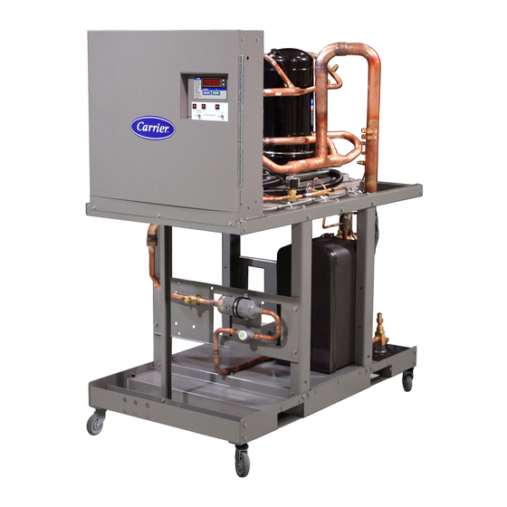
These installation instructions cover the 30MPA, MPW units
with ComfortLink controls. The 30MPA units are condenserless
units and the 30MPW units are all fluid cooled. See Fig. 1 and 2.
a30-5029
Fig. 1 - 30MPA Unit
Manufacturer reserves the right to discontinue, or change at any time, specifications or designs without notice and without incurring obligations.
Catalog No. 04-53300077-01
Installation Instructions
Page
Printed in U.S.A.
with Scroll Compressors
and COMFORTLINK™ Controls
a30-5030
Fig. 2 - 30MPW Unit
SAFETY CONSIDERATIONS
Installing, starting up, and servicing this equipment can be
hazardous due to system pressures, electrical components, and
equipment location (roofs, elevated structures, etc.).
Only trained, qualified installers and service technicians
should install, start up, and service this equipment.
When working on the equipment, observe precautions in the
literature and on tags, stickers, and labels attached to the
equipment.
• Follow all safety codes.
• Wear safety glasses and work gloves.
• Use care in handling, rigging, and setting bulky
equipment.
Electrical shock can cause personal injury and death. Shut
off all power to this equipment during installation. There
may be more than one disconnect switch. Tag all discon-
nect locations to alert others not to restore power until work
is completed.
Form 30MP-5SI
Pg 1
AQUASNAP
30MPA,MPW015-045
Liquid Chillers
WARNING
612
11-11
Replaces: 30MP-1SI
®
Advertisement
Table of Contents

Related Manuals for Carrier AQUASNAP 30MPA


Summary of Contents for Carrier AQUASNAP 30MPA
-
Page 1: Table Of Contents
® AQUASNAP 30MPA,MPW015-045 Liquid Chillers with Scroll Compressors and COMFORTLINK™ Controls Installation Instructions CONTENTS Page GENERAL ........1 SAFETY CONSIDERATIONS . -
Page 2: Installation
INSTALLATION WARNING Do not store units in an area exposed to weath- Location — DO NOT USE TORCH to remove any component. System er because of sensitive control mechanisms and electronic contains oil and refrigerant under pressure. devices. Locate unit indoors. Model number structure is shown in Fig. -
Page 3: Dimensions
a30-5032... - Page 4 a30-5033...
- Page 5 Table 1A — 30MPA,MPW015-045 Units Physical Data — English UNIT 30MPA,MPW NOMINAL TONS OPERATING WT (lb) 1097 1190 REFRIGERANT (lb) R-410A MPA* 10.7 12.5 14.7 15.1 11.8 15.3 21.0 27.3 34.5 COMPRESSOR Scroll, Hermetic Quantity Speed (rpm) 3500 3500 3500 3500 3500 Compressor Nominal Tons...
- Page 6 Table 1B — 30MPA,MPW015-045 Units Physical Data — SI UNIT 30MPA,MPW NOMINAL kW OPERATING WT (kg) REFRIGERANT (kg) R-410A MPA* 12.4 15.6 COMPRESSOR Scroll, Hermetic Quantity Speed (r/s) Compressor Nominal kW Oil Charge (L) Capacity Control — Standard No. of Steps Minimum Step Capacity (%) Capacity Control —...
-
Page 7: Step 1 - Inspect Shipment
NOTES: 1. Shaded areas indicate double discharge riser required if unit is Carrier recommends that these units be located in the base- equipped with hot gas bypass or operation below 40 F LWT (Leaving ment or on the ground floor. However, if it is necessary to lo- Water Temperature). - Page 8 a30-4997...
- Page 9 3. All wiring must comply with applicable local and national codes. 4. All piping must follow standard piping techniques. Refer to ® Carrier System Design Manual part 3, Carrier E20-II soft- ware Refrigerant Piping program, or appropriate ASHRAE (American Society of Heating, Refrigerating, and Air Condi- tioning Engineers) handbook for details on proper piping sizes and design.
-
Page 10: Evacuation And Dehydration
Ensure there is no gap be- guidelines. tween the two halves of the coupling. Carrier recommends that a field-supplied pressure relief de- 5. Alternately tighten the nuts with a wrench to draw the vice be installed in each discharge line of 30MPA units. Most coupling halves together uniformly. -
Page 11: 30Mpw Condenser
For variable primary flow applications, it may be necessary to adjust the flow switch set point to avoid nuisance trips. Con- tact Carrier service engineering for the method needed to adjust the switch. See Table 5 for minimum flow rates. See Table 6 for mini- mum loop volume. -
Page 12: Condenser Water Pressure Drop
ENGLISH 100 110 120 130 140 150 160 170 180 190 200 210 220 230 240 a30-5036 Liters/second LEGEND 1 — 30MP015 2 — 30MP020 a30-5037 3 — 30MP030 4 — 30MP040 5 — 30MP045 Fig. 12 — Condenser Water Pressure Drop... - Page 13 ENGLISH a30-5034 Liters/second LEGEND 1 — 30MP015 2 — 30MP020 a30-5035 3 — 30MP030 4 — 30MP040 5 — 30MP045 Fig. 13 — Evaporator Water Pressure Drop...
-
Page 14: Air Separation
Free chlorine (Cl Less than 1 ppm represents abuse and may impair or otherwise negatively Hydrogen Sulfide (H Less than 0.05 ppm affect the Carrier product warranty. Free (aggressive) Carbon Less than 5 ppm Dioxide (CO )† 1. Install a temporary bypass around the chiller to avoid cir- Total Hardness (dH) 4.0 –... -
Page 15: Filling The System
30MPW units, and can be field-installed. water system must accomplish three purposes: The Carrier flow switch accessory (part no. 30MP-900---004) 1. The entire piping system must be filled with water. is available for this purpose. Flow switch wiring terminals are 2. -
Page 16: Unbalanced 3-Phase Supply Voltage
Connections for condenser flow switch, chilled fluid pump 243 + 236 + 238 interlock, condenser pump interlock, remote alarm output, con- Average Voltage = denser output, and dual chiller thermistor accessory are made at these locations. See Fig. 17 for specific location of connec- = 239 v tions. - Page 17 a30-5338...
- Page 20 Copyright 2011 Carrier Corporation Manufacturer reserves the right to discontinue, or change at any time, specifications or designs without notice and without incurring obligations. Catalog No. 04-53300077-01 Printed in U.S.A. Form 30MP-5SI Pg 20 11-11 Replaces: 30MP-1SI...
Need help?
Do you have a question about the AQUASNAP 30MPA and is the answer not in the manual?
Questions and answers