Table of Contents
Advertisement
CONTENTS
SAFETY CONSIDERATIONS . . . . . . . . . . . . . . . . . . . . . . 1
GENERAL . . . . . . . . . . . . . . . . . . . . . . . . . . . . . . . . . . . . . . 1-3
INSTALLATION. . . . . . . . . . . . . . . . . . . . . . . . . . . . . . . . 4-43
Location . . . . . . . . . . . . . . . . . . . . . . . . . . . . . . . . . . . . . . . . . 4
Unit Mounting Requirements . . . . . . . . . . . . . . . . . . 21
Step 1 - Inspect Shipment. . . . . . . . . . . . . . . . . . . . . . 23
Step 2 - Position the Unit . . . . . . . . . . . . . . . . . . . . . . 23
Step 3 - Place the Unit . . . . . . . . . . . . . . . . . . . . . . . . . 23
Step 4 - Check Compressor Mounting . . . . . . . . . 23
Step 5 - Make Piping Connections . . . . . . . . . . . . . 24
• CONDENSER WATER CONTROL VALVE
• EVAPORATOR DESCRIPTION
• EVAPORATOR PIPING
• MULTI - UNIT CHILLER CONTROLLER
ACCESSORY
Step 6 - Fill the Chilled Water Loop . . . . . . . . . . . . 37
Step 7 - Make Electrical Connections . . . . . . . . . . 38
SAFETY CONSIDERATIONS
Installing, starting up, and servicing this equipment (Fig. 1-4)
can be hazardous due to system pressures, electrical compo-
nents, and equipment location (roofs, elevated structures, etc.).
Only trained, qualified installers and service technicians
should install, start up, and service this equipment.
When working on the equipment, observe precautions in the
literature and on tags, stickers, and labels attached to the
equipment.
• Follow all safety codes.
• Wear safety glasses and work gloves.
• Use care in handling, rigging, and setting bulky
equipment.
Catalog No. 04-53300182-01
Installation Instructions
Page
Printed in U.S.A.
and ComfortLink Controls
DO NOT USE TORCH to remove any component. System
contains oil and refrigerant under pressure.
To remove a component, wear protective gloves and gog-
gles and proceed as follows:
a. Shut off electrical power to unit.
b. Recover refrigerant to relieve all pressure from sys-
tem using both high-pressure and low pressure ports.
c. Traces of vapor should be displaced with nitrogen
and the work area should be well ventilated. Refrig-
erant in contact with an open flame produces toxic
gases.
d. Cut component connection tubing with tubing cutter
and remove component from unit. Use a pan to catch
any oil that may come out of the lines and as a gage
for how much oil to add to the system.
e. Carefully unsweat remaining tubing stubs when nec-
essary. Oil can ignite when exposed to torch flame.
Failure to follow these procedures may result in personal
injury or death.
.
Electrical shock can cause personal injury and death. Shut
off all power to this equipment during installation. There
may be more than one disconnect switch. Tag all discon-
nect locations to alert others not to restore power until work
is completed.
DO NOT re-use compressor oil or any oil that has been
exposed to the atmosphere. Dispose of oil per local codes
and regulations. DO NOT leave refrigerant system open to
air any longer than the actual time required to service the
equipment. Seal circuits being serviced and charge with
dry nitrogen to prevent oil contamination when timely
repairs cannot be completed. Failure to follow these proce-
dures may result in damage to equipment.
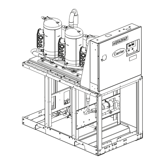
These installation instructions cover the 30MPA, MPW units
with ComfortLink controls. The 30MPA units are condenserless
units and the 30MPW units are fluid cooled. See Fig. 1-4 for dif-
ferent unit configurations. See Fig. 5 for model number no-
menclature and Fig. 6-19 for unit dimensional details and cor-
ner weights.
Form 30MP-21SI
Pg 1
AquaSnap
30MPA,MPW016-071
Liquid Chillers
with Scroll Compressors
50/60 Hz
WARNING
WARNING
CAUTION
GENERAL
1118
12-17
Replaces: 30MP-19SI
®
Advertisement
Table of Contents

Subscribe to Our Youtube Channel
Related Manuals for Carrier AquaSnap 30MPA050


Summary of Contents for Carrier AquaSnap 30MPA050
-
Page 1: Table Of Contents
® AquaSnap 30MPA,MPW016-071 Liquid Chillers with Scroll Compressors and ComfortLink Controls 50/60 Hz Installation Instructions CONTENTS WARNING Page DO NOT USE TORCH to remove any component. System SAFETY CONSIDERATIONS ..... . 1 contains oil and refrigerant under pressure. - Page 2 a30-6023 a30-6025 Fig. 1 — 30MPA Unit (Size 020-045) Fig. 3 — 30MPW Unit (Size 016-045) a30-6026 a30-6024 Fig. 4 — 30MPW Unit (Size 050-071) Fig. 2 — 30MPA Unit (Size 050-071)
- Page 3 30MP A 030 6 Packaging Options 30MP – AquaSnap ® Liquid Chiller with ComfortLink Controls 5 – Bag, No Compressor Insulation (Std) Condenser Option 7 – Bag, Compressor Insulation A – Chiller without Condenser (Air-Cooled) B – Export Crating, No Compressor Insulation W –...
-
Page 4: Installation
refrigeration connections (30MPA) or leave 2 ft (610 mm) INSTALLATION on one side for making fluid connections (30MPW) to condenser. See Fig. 6-17. WARNING The floor must be strong enough to support the unit operat- If a 30MPE electrical distribution panel is purchased, it is ing weight (see Tables 1-4, Fig. - Page 15 6" VICTAULIC CONNECTION 57.00 in. STYLE B: 11.38 in. (TYPICAL) TOP VIEW DETAIL A (CORNER POSTS REMOVED FOR CLARITY) UNIT SIZES 016-045: 65.05 in. UNIT SIZES 050-071: 68.81 in. SIDE VIEW SEE DETAIL A a30-6003 64.78 in. FRONT VIEW NOTE: Style B water manifold is used on 30MP050-071 units and 30MP016-045 units made starting February 2016 with a serial number beginning with 4515Q---- (example: Week 45, Year 2015, Q, sequence number).
- Page 16 57.00 in. 6" VICTAULIC STYLE B: 11.38 in. CONNECTIONS (TYPICAL) SPACER PIPE ACCESSORY TOP VIEW DETAIL A (CORNER POSTS REMOVED FOR CLARITY) UNIT SIZES 016-045: 65.05 in. UNIT SIZES 050-071: 68.81 in. SEE DETAIL A SIDE VIEW a30-6004 70.63 in. FRONT VIEW NOTE: Style B water manifold is used on 30MP050-071 units and 30MP016-045 units made starting February 2016 with a serial number beginning with 4515Q----...
- Page 17 Table 1 — 30MPA Air-Cooled and 30MPW Liquid-Cooled 016-045 Units Physical Data — English UNIT 30MPA,MPW 016** 032** NOMINAL TONS OPERATING WT (lb) — — MPA with Manifold — — 1146 1196 1214 1298 MPW with Manifold 1007 1226 1428 1404 1650 1734...
- Page 18 Table 2 — 30MPA Air-Cooled and 30MPW Liquid-Cooled 050-071 Units Physical Data — English UNIT 30MPA,MPW NOMINAL TONS OPERATING WT (lb) 1398 1413 1437 1468 1506 MPA with Manifold 1616 1631 1655 1686 1724 1602 1617 1681 1712 1719 MPW with Manifold 2038 2053 2117...
- Page 19 Table 3 — 30MPA Air-Cooled and 30MPW Liquid-Cooled 016-045 Units Physical Data — SI UNIT 30MPA,MPW 016** 032** NOMINAL kW OPERATING WT (kg) — — MPA with Manifold — — MPW with Manifold REFRIGERANT (kg) CKT A / CKT B R-410A MPA* —...
- Page 20 Table 4 — 30MPA Air-Cooled and 30MPW Liquid-Cooled 050-071 Units Physical Data — SI UNIT 30MPA,MPW NOMINAL kW OPERATING WT (kg) MPA with Manifold MPW with Manifold REFRIGERANT (kg) R-410A MPA* 13.5 14.0 15.0 15.5 17.7 19.6 20.3 21.6 22.4 22.8 COMPRESSOR Scroll, Hermetic...
-
Page 21: Unit Mounting Requirements
mounting frame. Each chiller MUST be supported in the The mounting hole Unit Mounting Requirements — center (under the heat exchangers) by the mounting frame; weights from Fig. 18 should be used for calculating weights for however, isolators are only necessary at the four corners of units connected via common water manifold piping (multi- each unit. - Page 22 CONTROL PANEL SIDE ESTIMATED WEIGHT DISTRIBUTION AT ESTIMATED WEIGHT DISTRIBUTION AT EACH MOUNTING HOLE — kg EACH MOUNTING HOLE — lb MOUNTING HOLE (kg) MOUNTING HOLE (lb) UNIT 30MP UNIT 30MP A020 A020 A030 A030 A040 A040 A045 A045 A050 A050 A055 A055...
-
Page 23: Step 1 - Inspect Shipment
NOTE: These units are not suitable for unprotected outdoor use. Carrier recommends that these units be located in the base- ment or on the ground floor. However, if it is necessary to lo- cate the unit on an upper floor, be sure the structure has been designed to support the unit weight. -
Page 24: Step 5 - Make Piping Connections
Condenser refrigerant piping for 30MPA units should be sized to minimize the amount of refrigerant required. Consider the length of piping required between the condenser and indoor unit, the amount of liquid lift, and the compressor oil return. The maximum length of refrigerant piping is 200 ft (61m). Discharge and liquid lines should be sized in accordance with Table 5. - Page 25 Fig. 24 —...
- Page 26 Fig. 25 —...
- Page 27 3. All wiring must comply with applicable local and national codes. 4. All piping must follow standard piping techniques. Refer to Carrier System Design Manual part 3, Carrier E20-II software Refrigerant Piping program, or appropriate ASHRAE (American Society of Heating, Refrigerating, and Air-Conditioning Engi- neers) handbook for details on proper piping sizes and design.
- Page 28 3. All wiring must comply with applicable local and national codes. 4. All piping must follow standard piping techniques. Refer to Carrier System Design Manual part 3, Carrier E20-II software Refrigerant Piping program, or appropriate ASHRAE (American Society of Heating, Refrigerating, and Air-Conditioning Engineers) handbook for details on proper piping sizes and design.
-
Page 29: 30Mpw Units With Nitrogen Charge
A strainer with a minimum of 40 mesh must be installed Carrier recommends that a field-supplied pressure relief de- within 10 ft (3 m) of the chiller closest to the water header vice be installed in each discharge line of 30MPA units. Most... - Page 30 10 ft (3 m) of the chiller closest to the water header inlet to prevent debris from clogging or damaging the chiller’s heat exchangers. See Carrier System Design Manual, Part 3, Piping Design, for chilled fluid piping details. The evaporator fluid inlet and outlet connections are Victau- lic.
- Page 31 ENGLISH Liters/Second LEGEND 30MP016 30MP045 1 — — 30MP020 30MP050,055 2 — — 30MP030 30MP060,065 3 — — 30MP032 30MP071 4 — — 30MP040 5 — NOTE: Pressure drop curves assume water temperature of 68°F (20°C). Fig. 30 — Evaporator Pressure Drop Curve, Standard Units...
- Page 32 ENGLISH Liters/Second LEGEND 30MP016 30MP045 1 — — 30MP020 30MP050,055 2 — — 30MP030 30MP060,065 3 — — 30MP032 30MP071 4 — — 30MP040 5 — NOTE: Pressure drop curves assume water temperature of 68°F (20°C). Fig. 31 — Evaporator Pressure Drop Curve, Style B* Manifold Units...
- Page 33 ENGLISH Liters/Second LEGEND 30MP016/020 30MP045 1 — — 30MP030 30MP050, 55 2 — — 30MP032 30MP060, 065, 071 3 — — 30MP040 4 — NOTE: Pressure drop curves assume water temperature of 68°F (20°C). Fig. 32 — Condenser Pressure Drop Curve, Standard Units...
- Page 34 ENGLISH Liters/Second LEGEND 30MP016/020 30MP045 1 — — 30MP030 30MP050, 55 2 — — 30MP032 30MP060, 065, 071 3 — — 30MP040 4 — NOTE: Pressure drop curves assume water temperature of 68°F (20°C). Fig. 33 — Condenser Pressure Drop Curve, Style B* Manifold Units...
-
Page 35: For Units With Water Manifold
FOR UNITS WITH WATER MANIFOLD — The water manage air in the system. Free air in the system can cause manifold is a factory-installed option, however the option noise, reduce terminal output, stop flow, or even cause pump comes with the leveling kit which must be field-installed. See failure due to pump cavitation. -
Page 36: Air Separation
COMMON LEAVING WATER TEMPERATURE 30MP MULTI-UNIT STRAINER CONTROL PANEL 30MP CHILLER SHIELDED GROUNDED WIRE 30MP CHILLER MS/TP NETWORK WIRING 30MP CHILLER Fig. 35 — Multi-Unit Control Panel Option a30-3226 DISTRIBUTION PUMP EXPANSION DECOUPLER TANK(S) AIR SEPARATOR WITH VENTS Fig. 36 — Typical Air Separator and Expansion Tank Location on Primary-Secondary Systems... -
Page 37: Step 6 - Fill The Chilled Water Loop
SYSTEM Freezing damage caused by an improperly cleaned system POT FEEDER AND represents abuse and may impair or otherwise negatively TRANSFER PUMP DILUTED affect the Carrier product warranty. CLEANING AGENT Table 10 — Water Quality Characteristics and Limitations TEMPORARY 30MP UNIT... -
Page 38: Step 7 - Make Electrical Connections
30MPW units, and Each circuit breaker has been sized for its particular chiller. can be field-installed. The Carrier flow switch accessory (part Proper installation is critical to ensure appropriate wire siz- no. 30MP-900---004) is available for this purpose. Flow switch ing, hazard avoidance, and compliance with local code(s). -
Page 39: Unbalanced 3-Phase Supply Voltage
UNBALANCED 3-PHASE SUPPLY VOLTAGE — Determine maximum deviation from average voltage: Use the following formula to determine the percent voltage (AB) 243 – 239 = 4 v imbalance: (BC) 239 – 236 = 3 v % Voltage Imbalance = (AC) 239 – 238 = 1 v max voltage deviation from average voltage Maximum deviation is 4 v. - Page 40 Table 11 —30MPA,MPW016-045 UNITS UNIT SIZE VOLTAGE COMPRESSOR A1 COMPRESSOR A2 COMPRESSOR A3 UNIT VOLTS 30MPA, NAMEPLATE MIN MAX RLA (EA) LRA (EA) RLA (EA) LRA (EA) RLA (EA) LRA (EA) MOCP REC FUSE 208/230-3-60 24.8 240.0 17.2 48.2 257.2 380-3-60 16.0 134.0...
- Page 41 Table 12 — Electrical Data — 30MPA,MPW050-071 Units with High Condensing Option VOLTAGE* COMPRESSOR A1 COMPRESSOR A2 UNIT UNIT SIZE VOLTS 30MPA, NAMEPLATE MOCP FUSE 208/230-3-60 85.1 85.1 191.5 521.1 380-3-60 49.3 49.3 110.9 301.3 460-3-60 40.7 40.7 91.6 252.7 575-3-60 32.6 32.6...
- Page 42 Table 13 — Electrical Data — 30MPW050-071 Units without High Condensing Option VOLTAGE* COMPRESSOR A1 COMPRESSOR A2 UNIT UNIT SIZE VOLTS 30MPW NAMEPLATE MOCP FUSE 208/230-3-60 79.4 79.4 178.7 497.1 380-3-60 48.1 48.1 108.2 300.3 460-3-60 39.7 39.7 89.3 251.9 575-3-60 31.8 31.8...
-
Page 44: Manufacturer Reserves The Right To Discontinue, Or Change At Any Time, Specifications Or Designs Without Notice And Without Incurring Obligations
© Carrier Corporation 2017 Manufacturer reserves the right to discontinue, or change at any time, specifications or designs without notice and without incurring obligations. Catalog No. 04-53300182-01 Printed in U.S.A. Form 30MP-21SI Pg 44 1118 12-17 Replaces: 30MP-19SI...
Need help?
Do you have a question about the AquaSnap 30MPA050 and is the answer not in the manual?
Questions and answers