Carrier 30HXC Series Installation, Operation And Maintenance Instructions
Screw compressor water-cooled liquid chillers and air-cooled liquid chillers
Hide thumbs
Also See for 30HXC Series:
Table of Contents
Advertisement
Advertisement
Table of Contents

Related Manuals for Carrier 30HXC Series


Summary of Contents for Carrier 30HXC Series
- Page 1 30HXC 080-375 30GX 082-358 Screw Compressor Water-Cooled Liquid Chillers and Air-Cooled Liquid Chillers 30HXC Nominal cooling capacity 290-1325 kW 30GX Nominal cooling capacity 285-1205 kW 50 Hz GLOBAL CHILLER Installation, operation and maintenance instructions...
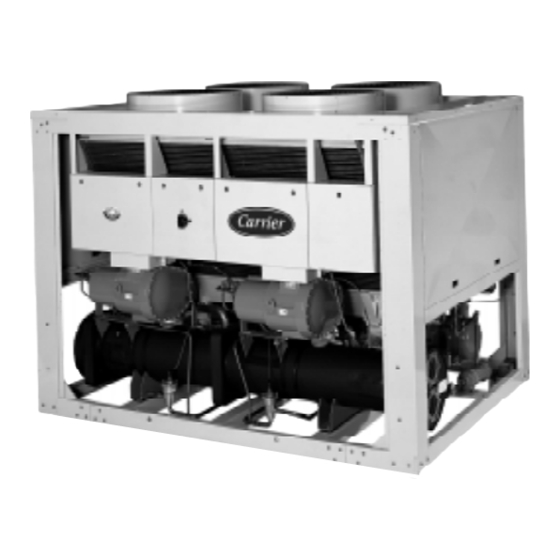
- Page 2 The cover photograph is for illustrative purposes only and is not part of any offer for sale or contract.
-
Page 3: Table Of Contents
List of contents INTRODUCTION ..............4 12 - ELECTRICAL CHARACTERISTICS ........ 23 12.1 - 30HXC ..................23 12.2 - 30GX ..................23 SAFETY CONSIDERATIONS ..........4 12.3 - 30HXC/GX ................23 DIMENSIONS, CLEARANCES, 13 - RECOMMENDED WIRE SECTIONS ........ 24 WEIGHT DISTRIBUTION ............. -
Page 4: Introduction
1 - INTRODUCTION LOCK OPEN AND TAG electrical circuits during servicing. IF WORK IS INTERRUPTED, check that all circuits are de- Prior to initial start-up of the 30HXC and 30GX unit, those energized before resuming work. involved in the start-up, operation, and maintenance should be DO NOT siphon refrigerant. -
Page 5: Dimensions, Clearances, Weight Distribution
3 - DIMENSIONS, CLEARANCES, WEIGHT DISTRIBUTION 3.1 - 30HXC 080-190 30HXC080 30HXC090 30HXC100 30HXC110 Evaporator Condenser Clearances required for operation and maintenance Clearances required for heat exchanger tube removal. Clearances D and E can be either on the left or on the right hand side. Water inlet Water outlet Power supply... -
Page 6: 30Hxc 200-375
3 - DIMENSIONS, CLEARANCES, WEIGHT DISTRIBUTION (CONT.) 3.2 - 30HXC 200-375 Evaporator Condenser Clearances required for operation and maintenance Clearances required for heat exchanger tube removal. Clearances D and E can be either on the left or on the right hand side. -
Page 7: 30Gx 082-182
3 - DIMENSIONS, CLEARANCES, WEIGHT DISTRIBUTION (CONT.) 3.3 - 30GX 082-182 Clearances required for operation and maintenance Clearances required for evaporator tube removal. Clearances can be either on the left or on the right hand side. Water inlet Water outlet 30GX-082 30GX-092 30GX-152... -
Page 8: 30Gx 207-358
DIMENSIONS, CLEARANCES, WEIGHT DISTRIBUTION (CONT.) 3.4 - 30GX 207-358 Clearances required for operation and maintenance Clearances required for evaporator tube removal. Clearances can be either on the left or on the right hand side. Water inlet Water outlet 30GX-207 30GX-227 30GX-247 Power supply 30GX-267... -
Page 9: Physical Data 30Hxc
Circuit A/B 39/36 39/36 37/32 38/38 57/55 59/50 56/50 59/52 58/61 60/70 110/58 118/63 120/75 120/75 108/110 110/110 110/120 Polyolester oil CARRIER SPEC: PP 47-32 Circuit A/B 15/15 15/15 15/15 15/15 15/15 15/15 15/15 15/15 15/15 15/15 30/15 30/15 30/15... - Page 10 Compressors Reference Size I nom. LRA (Y) LRA (S) 1 cp. LRA (S) 2 cp. 06NW2146S7N 06NW2174S7N 06NW2209S7N 06NW2250S7N 06NW2300S5N 06NW2300S5E Legend: 06NW - Compressor for water-cooled units - Non-economized compressor - Economized compressor INOM - Average current draw of the compressor at Eurovent conditions - Must hold amperes (maximum operating current) at 360 V - Locked rotor current with across-the-line start LRA (Y)
-
Page 11: Electrical Data For Units With High Condensing Temperatures
6 - ELECTRICAL DATA FOR UNITS WITH HIGH CONDENSING TEMPERATURES 30HXC 150 and 150A Options 30HXC Power circuit Nominal power supply (Un) V-ph-Hz 400-3-50 Voltage range 360-440 Control circuit supply The control circuit is supplied via the factory-installed transformer Max. power input** Circuit A Circuit B Max. -
Page 12: Physical Data 30Gx
Refrigerant charge HFC-134a Circuit A/B 55/55 58/50 54/53 55/53 60/57 63/60 75/69 75/75 80/80 130/85 130/85 155/98 170/104 162/150 162/165 175/175 Polyolester oil CARRIER SPEC: PP 47-32 Circuit A/B 20/20 20/20 20/20 20/20 20/20 20/20 20/20 20/20 20/20 40/20 40/20 40/20... -
Page 13: Application Data
°C Available static pressure Notes: * For application requiring operation at less than 6.8°C, contact Carrier s.a. for unit EVAPORATOR selection using the Carrier electronic catalog. ** For application requiring operation at less than 4°C, the units require the use of antifreeze. -
Page 14: Variable Flow Evaporator
9.4 - Variable flow evaporator 9.6 - Cooler flow rate (l/s) Variable evaporator flow can be used in standard 30HXC and 30HXC Min.* Max.** 30GX chillers. The chillers maintain a constant leaving water 080-090 22.7 24.1 temperature under all flow conditions. For this to happen, the 27.5 minimum flow rate must be higher than the minimum flow 120-130... -
Page 15: Evaporator Pressure Drop Curve
9.8 - Evaporator pressure drop curve Water flow rate, l/s 30HXC 080-090/30GX 082 30HXC 175-190/30GX 182 30HXC 100/30GX 092-102 30HXC 200/30GX 207-227 30HXC 110/30GX 112-122 30HXC 230/30GX 247 30GX 132 30HXC 260-285/30GX 267 30HXC 120-130 30HXC 310/30GX 298 30HXC 140-155/30GX 152-162 30HXC 345-375/30GX 328-358... -
Page 16: Condenser Pressure Drop Curve
9.9 - Condenser pressure drop curve Water flow rate, l/s 30HXC 080-090-100-110 30HXC 200 30HXC 120-130 30HXC 230-260-285 30HXC 140-155 30HXC 310-345-375 30HXC 175-190... -
Page 17: Flow Controllers
30HXC and 30GX. Compare the nameplate data with the order. Failure to this instruction will void Carrier guarantee. • Confirm that all accessories ordered for on-site installation have been delivered, and are complete and undamaged. -
Page 18: Lifting Instructions
11 - LIFTING INSTRUCTIONS 11.1 - 30HXC 080-190 This diagram is shown for information only. Refer to “certified drawings”. 2000 mm mini. 1200 mm mini. R-134a X mm Y mm Z mm 30HXC080 30HXC090 1345 30HXC100 Ø 13.5 30HXC110 1368 30HXC120 30HXC130 1731... -
Page 19: 30Hxc 200-285
11 - LIFTING INSTRUCTIONS (CONT.) 11.2 - 30HXC 200-285 This diagram is shown for information only. Refer to “certified drawings”. 2800 mm min. 1200 mm min. 2075 Ø 13.5 11.3 - 30HXC 310-375 3500 mm min. 1200 mm min. X mm Y mm Z mm 2195... -
Page 20: 30Gx 082-162
11 - LIFTING INSTRUCTIONS (CONT.) 11.4 - 30GX 082-162 This diagram is shown for information only. Refer to “certified drawings”. 2000 mm min. 60 MAX 2.5 T 60@27MINI 2300 mm min. (P1 a P4) P1 a P4 X mm Y mm Z mm PTkg 30GX082... -
Page 21: 30Gx 207-267
11 - LIFTING INSTRUCTIONS (CONT.) 11.6 - 30GX 207-267 This diagram is shown for information only. Refer to “certified drawings”.. 2000 mm min. 60 MAX 2.5 T 60 MINI 2300 mm min. (P1 a P6) P1 a P6 X mm Y mm Z mm PTkg... -
Page 22: Piping Connections
11.8 - Piping connections 11.8.3 - Freeze protection Evaporator and water-cooled condenser protection Refer to the certified dimensional drawings for the sizes and If the chiller or the water piping is in an area where the positions of all water inlet and outlet connections. The water ambient temperature can fall below 0°C it is recommended to pipes must not transmit any radial or axial force to the heat add an antifreeze solution to protect the unit and the water... -
Page 23: Electrical Characteristics
(or characteris- tics not referred to here) contact your Carrier representative. Annex B of standard EN 60204-1 may be used to describe the electrical characteristics under which the machines operate. -
Page 24: Recommended Wire Sections
The following is only to be used as a guideline, and conduit. does not make Carrier in any way liable. After wire sizing has For 30GX units installed outside the building: No.17: been completed, using the certified dimensional drawing, the suspended aerial lines, and No. -
Page 25: Field Control Wiring
IMPORTANT Evaporator pump interlock (mandatory) Before connection of the main power cables (L1 - L2 - L3) Remote on/off switch on the terminal block, it is imperative to check the correct Condenser flow switch (field-supplied, 30HXC only) order of the 3 phases before proceeding to the connection on Remote heat/cool switch then terminal block or the main disconnect/isolator switch. -
Page 26: Major System Components And Operation Data
A series of calibrated slots are located inside the orifice following lubrifiant. assembly. As refrigerant passes through the orifice, the pres- CARRIER MATERIAL SPEC PP 47-32 sure drops and the refrigerant changes to a 2-phase condition (liquid and vapor). To control refrigerant flow for different 14.1.4 - Oil Supply Solenoid Valve... -
Page 27: Oil Pumps
14.10 - Thermistors desired liquid level in the cooler (as is done for Non- Economized chillers). The float valve maintains a liquid level 14.10.1 - Evaporator leaving fluid in the bottom of the economizer. Liquid refrigerant is supplied This temperature is used to measure the leaving evaporator from the condenser to the bottom of the economizer. -
Page 28: 30Gx Fan Arrangement
14.11 - 30GX fan arrangement EV31 EV32 EV31 EV32 EV33 EV31 EV32 EV33 EV34 EV12 EV11 EV13 EV12 EV11 EV14 EV13 EV12 EV11 GX082/102 GX112/132 GX152/162 EV31 EV33 EV13 EV11 EV31 EV33 EV15 EV13 EV11 EV32 EV34 EV14 EV12 EV32 EV34 EV16 EV14... -
Page 29: Maintenance
Freezing damage is considered abuse and may void checking the EXD position. the Carrier warranty. 6. When the EXD Percent Open is in the range of 40 - 60%, CAUTION check the liquid line sightglass. -
Page 30: Pressure Transducers
5. Using a suitable pump, add 2 litres of Polyolester oil to the return to operation. system (CARRIER SPEC: PP47-32). Make sure that the oil level safety switch is NOT jumpered, and allow the unit to re-start and run normally. - Page 31 If it is believed that the valve is not working properly, The switch that has been selected for detecting reverse rotation contact your Carrier service department for further checks on: is Carrier part number HK01CB001. It is available as part of the "Compressor installation package" (part No. 06NA 660 •...
-
Page 32: Start-Up Ckecklist For 30Hxc/Gx Liquid Chillers
16 - START-UP CKECKLIST FOR 30HXC/GX LIQUID CHILLERS (USE FOR JOB FILE) Preliminary information Job name: ........................................ Location: ......................................... Installing contractor: ....................................Distributor: ......................................Start-up preformed by: ................................... Compressors Model: ..................... S/N ....................Compresseurs Circuit A Circuit B 1. Model # ..................1. Model # ................. S/N ..................... - Page 33 Check condenser system (30HXC) All condenser water valves are open All condenser piping is connected properly All air has been vented from the system Condenser water pump (CWP) is operating with the correct rotation. Condenser water pump amperage: Rated:…….. Actual……… Unit start-up CWP starter has been properly interlocked with the chiller Oil heaters have been energized for at least 24 hours (30GX)
- Page 34 Check pressure drop across the condenser (30HXC only) Entering condenser = ........ (kPa) Leaving condenser = ........ (kPa) (Leaving - entering) = ......(kPa) WARNING Plot condenser pressure drop on performance data chart (in product data literature) to determine total liters per second (l/s) and find unit's minimum flow rate.
- Page 36 Order No: 13173-76, 03 1999 - Supersedes No: 13173-76, March 1998 Manufacturer: Carrier s.a., Montluel, France. Manufacturer reserves the right to change any product specifications without notice. Printed in the Netherlands on chlorine-free paper.
Need help?
Do you have a question about the 30HXC Series and is the answer not in the manual?
Questions and answers