
Related Manuals for Meyer Sound 1100-LFC


Summary of Contents for Meyer Sound 1100-LFC
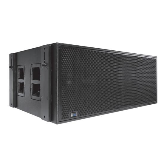
- Page 1 OPERATING INSTRUCTIONS 1100-LFC Low-Frequency Control Element Keep these important operating instructions. Check www.meyersound.com for updates.
- Page 2 GuideALink, Intelligent AC, LEO, LEO-M, RMS, QuietCool, and all alpha-numeric designations for Meyer Sound products and accessories are trademarks of Meyer Sound. Galileo, MAPP Online Pro, Meyer Sound, the Meyer Sound wave logo, MICA, MILO, and SIM are regis- tered trademarks of Meyer Sound Laboratories Inc. (Reg. U.S. Pat. & Tm. Off.). All third-party trademarks mentioned herein are the prop-...
- Page 3 FEDERAL COMMUNICATIONS COMMISSION (FCC) STATEMENT This equipment has been tested and found to comply with the limits for a Class A digital device, pursuant to part 15 of the FCC Rules. These limits are designed to provide reasonable protection against harmful interference when the equipment is operated in a commercial environment.
-
Page 4: Important Safety Instructions
2. Keep these instructions. 12. Use only with the caster rails or rigging specified by 3. Heed all warnings. Meyer Sound, or sold with the loudspeaker. Handles are 4. Follow all instructions. for carrying only. 5. Do not use this loudspeaker near water. -
Page 5: Safety Summary
SAFETY SUMMARY English Ne pas installer l’haut-parleur dans un Um ein Überhitzen dem Lautsprecher endroit où il y a de l’eau ou une zu verhindern, das Gerät vor direkter To reduce the risk of electric shock, dis- humidité... -
Page 7: Table Of Contents
RMS Software RMS Module Neuron ID for RMS Module Resetting the RMS Module Chapter 6: System Design and Integration Tools MAPP Online PRO SIM 3 Measurement System Appendix A: Optional Weather Protection Expanding the 1100-LFC Rain Hood Appendix B: 1100-LFC Specifications... - Page 8 CONTENTS viii...
-
Page 9: Chapter 1: Introduction
This ultralow distortion, cou- Meyer Sound’s RMS™ remote monitoring system comes pled with exceptional headroom and optimized rigging standard with all 1100-LFCs and provides comprehensive options, makes the 1100-LFC a flexible tool for low-end ® monitoring of system parameters on a Windows -based directional applications for large-scale tours and installa- computer. - Page 10 CHAPTER 1: INTRODUCTION The optional MRK-1100 rigging kit, available as a factory- For touring and portable systems, the 1100-LFC can travel installed option or field upgrade, includes captive securely in stacks of three units with the optional MCF-1100 GuideALinks that allow the loudspeaker to be flown from the caster frame.
-
Page 11: Chapter 2: Power Requirements
AC line polarity and connect the earth ground The 1100-LFC ships with a powerCON 32 cable mount con- on both ends of the cable. The 1100-LFC requires a nector, also rated at 32 A, for assembling AC power cables. -
Page 12: 1100-Lfc Voltage Requirements
Neutral Earth/Grnd If the voltage drops below 208 V (brownout), the 1100-LFC Figure 1: 220 V AC, 3-Phase Wye System (Single Line to Loudspeakers) uses stored power to continue operating temporarily; the loudspeaker shuts down if the voltage does not rise above Because the 1100-LFC can tolerate elevated voltages from the low boundary before the stored power is used. -
Page 13: 1100-Lfc Current Requirements
The minimum electrical service amperage required by an 1100-LFC loudspeaker system is the sum of the maximum The current draw for the 1100-LFC is dynamic and fluctu- long-term continuous current for each loudspeaker. An addi- ates as operating levels change. Since different cables and... -
Page 14: Electrical Safety Guidelines
Use the cable rings (see “Cable Rings” on page 16) ■ located on rear of the 1100-LFC to reduce strain on the AC power cable (and audio cables). Do not use the cable rings for any other purpose. -
Page 15: Chapter 3: Amplification And Audio
CHAPTER 3: AMPLIFICATION AND AUDIO The low-frequency drivers in the 1100-LFC are powered by a Audio Input (XLR 5-Pin Female) 2-channel proprietary Meyer Sound amplifier with bridged The audio Input is an XLR 5-pin female connector and MOSFET output stages. The audio signal is processed with an... -
Page 16: Optional Xlr 3-Pin Audio Connectors
CABLE RINGS sure the source device can drive the total load impedance of Two cable rings are provided on the rear of the 1100-LFC the looped loudspeakers. In addition, the source device loudspeaker. The power and audio cables should be tied off... -
Page 17: Amplifier Cooling System
6 inches behind the LF Limit LED loudspeaker for proper ventilation. The two low-frequency drivers for the 1100-LFC are pow- ered by separate amplifier channels that are routed to a sin- 1100-LFC Fans gle limiter. When a safe power level is exceeded in either... - Page 18 CHAPTER 3: AMPLIFICATION AND AUDIO...
-
Page 19: Chapter 4: Quickfly Rigging
MRK-1100 rigging kit. Protective, plastic skids This chapter provides an overview of QuickFly rigging are included on the bottom of the 1100-LFC cabinet that options for the 1100-LFC. For complete information on the securely align with the slots on the cabinet top. Units can be rigging hardware, including dimensions, weight, configura- stacked normally or reversed for cardioid configurations. -
Page 20: 1100-Lfc Stacked Cardioid Arrays
CHAPTER 4: QUICKFLY RIGGING 1100-LFC STACKED CARDIOID ARRAYS MRK-1100 RIGGING KIT The 1100-LFC can be configured in cardioid arrays to reduce The optional MRK-1100 rigging kit allows the 1100-LFC to be output heard behind the loudspeakers. The loudspeaker’s lin- flown from the MTG-1100 top grid. The rigging kit is available... -
Page 21: Mtg-1100 Top Grid
The MTG-1100 is symmetrical and its front/rear orientation for each GuideALink: one to secure the link in the bottom unit, does not matter when attaching to the 1100-LFC. The grid and one to secure the link to the top (linked) unit. Eight has four bottom link slots, two on each side of the grid, that 1/2 x 1.25-inch quick-release pins (blue) are included with... -
Page 22: Mas-1100 Array Spacer
1/2 x 1.50-inch quick-release pins included with the 1100-LFC. The array spacer has four bottom slots, two on each side, that accept GuideALinks from the cabinet below. 7/8-inch... -
Page 23: Mcf-1100 Caster Frame
MRK-1100 rigging kit (see Figure 3). Figure 4: MCF-1100 Caster Frame with 1100-LFC Stack with Rigging Kits (MTG-1100 Top Grid on Top) TIP: The MTG-1100 top grid can travel installed on top of 1100-LFC stacks. - Page 24 Avoid moving stacks in the front-to-back direction of the 1100-LFCs (the long side); always move stacks sideways to avoid tipping. When lifting an 1100-LFC stack with a forklift, always ■ keep the forks wide and close to the caster frame’s wheels.
-
Page 25: Chapter 5: Rms Remote Monitoring System
CHAPTER 5: RMS REMOTE MONITORING SYSTEM The 1100-LFC includes an RMS module that allows the RMS SOFTWARE loudspeaker to be connected to an RMS network. RMS pro- RMS software provides extensive system status and perfor- vides real-time monitoring of multiple Meyer Sound self- mance data for each loudspeaker, including amplifier volt- powered loudspeakers from a Windows-based computer. -
Page 26: Rms Module
RMS software displays all loudspeakers on the network in a RMS MODULE panel with icons, Meter views, and Text views that can be The 1100-LFC RMS user panel includes an Identify button, a customized to suit your needs. Loudspeaker data is Wink/Activity LED, and two Network connectors. -
Page 27: Neuron Id For Rms Module
Wink/Activity LED (Green) RESETTING THE RMS MODULE The green Wink/Activity LED indicates the status of the You can use the Identify button to reset the 1100-LFC RMS loudspeaker: module when powering up the loudspeaker. This will cause the module to be decommissioned from the network. - Page 28 CHAPTER 5: RMS REMOTE MONITORING SYSTEM...
-
Page 29: Chapter 6: System Design And Integration Tools
Meyer Sound’s patented online acoustical prediction tool, are based on 360 1/48th-octave-band measurements taken and SIM 3, a comprehensive system for measurement and with a SIM audio analyzer in the Meyer Sound anechoic analysis. chamber. The extraordinary consistency between Meyer Sound loudspeakers guarantees that predictions from MAPP Online Pro will closely match their actual performance. -
Page 30: Sim 3 Measurement System
SIM 3 Applications The MAPP Online Pro client software is regularly upgraded to add support for the latest Meyer Sound loudspeakers, as well SIM 3’s main applications are testing and aligning loud- as to add feature enhancements. Most upgrades are down-... -
Page 31: Appendix A: Optional Weather Protection
APPENDIX A: OPTIONAL WEATHER PROTECTION The 1100-LFC is optionally available with weather protection for fixed, outdoor installations. Weather-protected units include a collapsible rain hood that protect’s the loudspeaker’s connectors from direct exposure to rainfall. EXPANDING THE 1100-LFC RAIN HOOD To expand the 1100-LFC rain hood: 1. - Page 32 APPENDIX A: OPTIONAL WEATHER PROTECTION...
-
Page 33: Appendix B: 1100-Lfc Specifications
APPENDIX B: 1100-LFC SPECIFICATIONS ACOUSTICAL Operating Frequency 28 Hz – 100 Hz Range Note: Recommended maximum operating frequency range. Response depends on loading condi- tions and room acoustics. Frequency Response 30 Hz – 85 Hz ±4 dB Note: Measured free field with 1/3 octave frequency resolution at 4 meters. - Page 34 APPENDIX B: 1100-LFC SPECIFICATIONS Current Draw Idle Current 0.6 A rms (230 V AC) Maximum Long-Term 10.5 A rms (230 V AC) Continuous Current Burst Current 18 A rms (230 V AC) Ultimate Short-Term 53 A peak (230 V AC)
- Page 35 1100-LFC OPERATING INSTRUCTIONS 1100-LFC COMPLIANCE FCC Verified Class A 1100-LFC DIMENSIONS 33.00 52.60 [838 mm] [1336 mm] 20.48 [520 mm] 10.65 [270 mm] 36.00 16.65 [914 mm] [423 mm] 54.65 [1388 mm] 20.10 [511 mm] 1100-LFC Dimensions NOTE: For dimensions and weight for the MTG-1100 top grid, MAS-1100 array spacer, and MCF-1100 caster...
- Page 36 APPENDIX B: 1100-LFC SPECIFICATIONS 1100-LFC Dimensions with Rain Hood 8.50 33.00 52.60 [216 mm] [838 mm] [1336 mm] 20.48 [520 mm] 10.65 [270 mm] 36.00 16.65 [914 mm] [423 mm] 54.65 41.27 [1388 mm] [1048 mm] 6.25 [159 mm] 20.10...
- Page 40 Meyer Sound Laboratories Inc. 2832 San Pablo Avenue Berkeley, CA 94702 www.meyersound.com © 2013 T: +1 510 486.1166 Meyer Sound Laboratories Inc. F: +1 510 486.8356 1100-LFC Operating Instructions, PN 05.220.005.01 A...
Need help?
Do you have a question about the 1100-LFC and is the answer not in the manual?
Questions and answers