
Related Manuals for Husqvarna 96193002300


Summary of Contents for Husqvarna 96193002300
- Page 1 2008-01 Operator's Manual O0802016 Snow Thrower 1330 SBE OV 96193002300 Operator's Manual...
-
Page 2: Safety Rules
Safe Operation Practices for Walk-Behind Snow Throwers This snow thrower is capable of amputating hands and feet and throwing objects. Failure to observe the following safety instructions could result in serious injury. Look for this symbol to point out im- por tant safety precautions. -
Page 3: Table Of Contents
6. When cleaning, repairing or inspecting the snow thrower, stop the engine and make certain the collector/impeller and all moving parts have stopped. Disconnect the spark plug wire and keep the wire away from the plug to prevent someone from accidentally starting the en- gine. - Page 4 PARTS PACKED SEPARATELY IN CARTON...
-
Page 5: Assembly / Pre-Operation
ASSEMBLY / PRE-OPERATION Read these instructions and this manual in its entirety before you attempt to assemble or operate your new snow thrower. Reading the entire manual will familiarize you with the unit, which will assist you in assembly, operation and maintenance of the product. Your new snow thrower has been as sem bled at the factory with the ex cep tion of those parts left unassembled for shipping purposes. - Page 6 ASSEMBLY / PRE-OPERATION INSTALL TRACTION DRIVE CONTROL ROD (See Figs. 3 and 4) The traction drive control rod has the long loop on the end of the spring as shown. 1. Slide rubber sleeve up rod and hook end of spring into pivot bracket with loop opening down as shown.
- Page 7 ASSEMBLY / PRE-OPERATION INSTALL DISCHARGE CHUTE / CHUTE ROTATOR HEAD (See Fig. 7) NOTE: The multi-wrench provided in your parts bag may be used to install the chute rotator head. 1. Place discharge chute assembly on top of chute base with discharge opening toward front of snow thrower.
-
Page 8: Know Your Snow Thrower
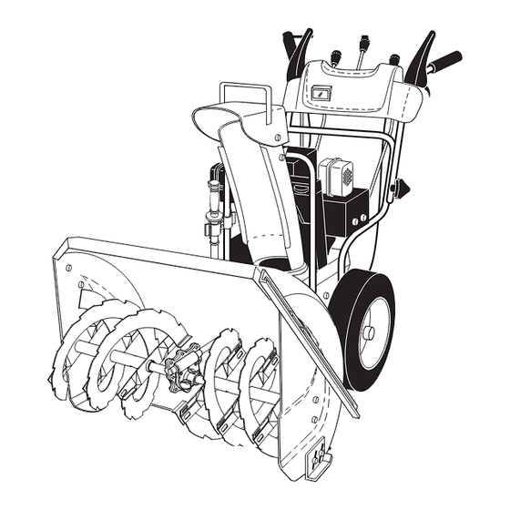
OPERATION KNOW YOUR SNOW THROWER READ THIS OWNER'S MANUAL AND ALL SAFETY RULES BEFORE OPERATING YOUR SNOW THROWER. Compare the illustrations with your snow thrower to familiarize yourself with the location of various controls and adjustments. Save this manual for future reference. These symbols may appear on your snow thrower or in literature supplied with the product. - Page 9 SPARK PLUG SAFETY IGNITION CHOKE CON- TROL THROTTLE / ENGINE CONTROL RECOIL POWER (AUXILIARY) CORD STARTER PLUG ELECTRIC HANDLE START BUTTON PRIM ER NOTE: ITEMS ABOVE ARE SHOWN IN THEIR TYPICAL LOCATION ON THE ENGINE. ACTUAL LOCATION MAY VARY WITH THE ENGINE ON YOUR UNIT.
-
Page 10: How To Use Your Snow Thrower
The operation of any snow thrower can result in foreign objects thrown into the eyes, which can result in severe eye damage. Always wear safety glasses or eye shields while operating your snow thrower or performing any ad just - ments or repairs. - Page 11 AUGER CONTROL LEVER FIG. 15 USING THE CLEAN-OUT TOOL (See Fig. 16) In certain snow conditions, the discharge chute may be- come clogged with ice and snow. Use the clean-out tool to dislodge this blockage. When cleaning, repairing, or in spect ing, make certain all controls are disengaged and the auger/impeller and all moving parts have stopped.
-
Page 12: Before Starting The Engine
NOTE: It is not recommended to operate the snow thrower over gravel or rocky surfaces. Objects such as gravel, rocks or other debris, can easily be picked up and thrown by the impeller, which can cause serious personal injury, property dam age or damage to the snow thrower. -
Page 13: If Recoil Starter Has Frozen
TO START ENGINE • Be sure fuel shut-off valve is in the OPEN position. Your snow thrower engine is equipped with both a 120 Volt A.C. electric starter and a recoil starter. The electric starter is equipped with a three-wire power cord and plug and is designed to operate on 120 Volt A.C. -
Page 14: Maintenance
GENERAL REC OM MEN DA TIONS The warranty on this snow thrower does not cover items that have been sub ject ed to operator abuse or negligence. To receive full value from the warranty, operator must maintain snow thrower as in struct ed in this manual. Some ad just - ments will need to be made periodically to properly maintain your snow thrower. -
Page 15: Snow Thrower
SNOW THROWER Always observe safety rules when performing main te nance. TIRES • Maintain proper air pressure in both tires (14–17 P.S.I. / 19-24.5 N-m). • Keep tires free of gasoline / oil, which can harm rubber. NOTE: To seal tire punctures and prevent fl at tires due to slow leaks, tire sealant may be purchased from your local parts dealer. -
Page 16: Service And Adjustments
SERVICE AND ADJUSTMENTS WARNING: To avoid serious injury, before per- forming any service or ad just ments: 1. Be sure throttle is in STOP position. 2. Remove safety ignition key. 3. Make sure the augers and all mov ing parts have completely stopped. 4. -
Page 17: To Replace Belts
SERVICE AND ADJUSTMENTS TO REPLACE BELTS (See Fig. 24) The auger and traction drive belts are not adjustable. If the belts are damaged or begin to slip from wear, they should be replaced. It is recommended that the belt(s) be replaced by an authorized service centre/department. -
Page 18: Storage
TO REMOVE WHEELS (See Fig. 25) • Remove the bolt and nut; remove wheel from axle. NOTE: To seal punctures or prevent fl at tires due to slow leaks, tire sealant may be purchased from your local parts dealer. Tire sealant also prevents tire dry rot and cor ro sion. BOLT FIG. -
Page 19: Troubleshooting
TROUBLESHOOTING See appropriate section in manual unless directed to a qualifi ed service center. PROBLEM CAUSE Does not start 1. Fuel shut-off valve (if so equipped) in OFF position. 2. Safety ignition key is not inserted. 3. Out of fuel. 4. -
Page 20: Repair Parts
REPAIR PARTS AUGER HOUSING / IMPELLER ASSEMBLY SNOW THROWER - MODEL NUMBER 1330SBE-OV (96193002300) - Page 21 REPAIR PARTS SNOW THROWER - MODEL NUMBER 1330SBE-OV (96193002300) KEY PART DESCRIPTION 532 18 25-16 Bar, Weight 532 75 11-53 Nut, Hex 5/16-18 872 11 05-10 Bolt, Carriage 5/16-18 x 1-1/4 532 19 10-79 Pulley, Impeller 532 18 89-09 Bearing Assembly, Flange...
- Page 22 REPAIR PARTS CONTROL PANEL / DISCHARGE CHUTE SNOW THROWER - MODEL NUMBER 1330SBE-OV (96193002300)
- Page 23 REPAIR PARTS SNOW THROWER - MODEL NUMBER 1330SBE-OV (96193002300) KEY PART NOTE: All component dimensions given in U.S. inches. IMPORTANT: Use only Original Equipment Manufacturer (O.E.M.) replacement parts. Failure to do so could be hazardous, damage your snow thrower and void your warranty.
- Page 24 REPAIR PARTS HANDLES SNOW THROWER - MODEL NUMBER 1330SBE-OV (96193002300)
- Page 25 REPAIR PARTS SNOW THROWER - MODEL NUMBER 1330SBE-OV (96193002300) KEY PART NOTE: All component dimensions given in U.S. inches. IMPORTANT: Use only Original Equipment Manufacturer (O.E.M.) replacement parts. Failure to do so could be hazardous, damage your snow thrower and void your warranty.
- Page 26 REPAIR PARTS DRIVE SNOW THROWER - MODEL NUMBER 1330SBE-OV (96193002300)
- Page 27 REPAIR PARTS SNOW THROWER - MODEL NUMBER 1330SBE-OV (96193002300) KEY PART NOTE: All component dimensions given in U.S. inches. IMPORTANT: Use only Original Equipment Manufacturer (O.E.M.) replacement parts. Failure to do so could be hazardous, damage your snow thrower and void your warranty.
- Page 28 REPAIR PARTS CHASSIS / ENGINE / PULLEYS SNOW THROWER - MODEL NUMBER 1330SBE-OV (96193002300)
- Page 29 REPAIR PARTS SNOW THROWER - MODEL NUMBER 1330SBE-OV (96193002300) KEY PART 532 15 54-15 Washer, Flat 532 16 67-85 Nut, Jam, Lock 5/16-18 532 17 53-30 Pin, Idler Pivot 532 41 19-31 Belt, Traction Variator 810 04 05-00 Washer, Lock 5/16...
- Page 30 REPAIR PARTS WHEELS / DECALS SNOW THROWER - MODEL NUMBER 1330SBE-OV (96193002300)
- Page 31 REPAIR PARTS SNOW THROWER - MODEL NUMBER 1330SBE-OV (96193002300) NOTE: All component dimensions given in U.S. inches. IMPORTANT: Use only Original Equipment Manufacturer (O.E.M.) replacement parts. Failure to do so could be hazardous, damage your snow thrower and void your warranty.
-
Page 32: Warranty
It is the Owner’s and Retailer’s responsibility to make certain that the Warranty Registration Card is properly filled out and mailed to Husqvarna Forest & Garden Company. This card should be mailed within ten (10) days from the date of purchase in order to confirm the warranty and to facilitate post-sale service.
Need help?
Do you have a question about the 96193002300 and is the answer not in the manual?
Questions and answers