Table of Contents
Advertisement
Advertisement
Table of Contents

Related Manuals for Husqvarna 96193005500


Summary of Contents for Husqvarna 96193005500
- Page 1 924SB Owner's Manual...
-
Page 2: Safety Rules
Safe Operation Practices for Walk-Behind Snow Throwers This snow thrower is capable of amputating hands and feet and throwing objects. Failure to observe the following safety instructions could result in serious injury. Look for this symbol to point out im- por tant safety precautions. -
Page 3: Table Of Contents
6. When cleaning, repairing or inspecting the snow thrower, stop the engine and make certain the collector/impel- ler and all moving parts have stopped. Disconnect the spark plug wire and keep the wire away from the plug to prevent someone from accidentally starting the engine. -
Page 4: Assembly / Pre-Operation
PARTS PACKED SEPARATELY IN CARTON (2) FLAT WASHERS IGNITION KEY (S) (2) CARRIAGE BOLTS 3/8-16 x 2.25 (1) WASHER 3/8 (2) HANDLE KNOBS (19131316) ASSEMBLY / PRE-OPERATION Read these instructions and this manual in its entirety before you attempt to assemble or operate your new snow thrower. - Page 5 ASSEMBLY / PRE-OPERATION NOTE: The multi-wrench may be used for assembly of the chute rotator head to snow thrower and making ad just ments to the skid plates. UNFOLD UPPER HANDLE 1. Raise upper handle to the operating position and tight en handle knobs securely.
- Page 6 ASSEMBLY / PRE-OPERATION INSTALL AUGER CONTROL ROD (See Figs. 5 and 6) 1. Retrieve vinyl sleeve and spring from bag of parts and retrieve the auger control rod from carton chute tray. Slide straight rod end through the small hole in the vinyl sleeve.
- Page 7 ASSEMBLY / PRE-OPERATION INSTALL CHUTE DEFLECTOR REMOTE CONTROL (See Figs. 8 and 9) 1. Install remote cable bracket to discharge chute with 5/16-18 carriage bolt and 5/16-18 locknut as shown. Tighten securely. 2. Install remote cable eyelet to chute deflector with 1/4-20 shoulder bolt and 1/4-20 locknut as shown.
-
Page 8: Know Your Snow Thrower
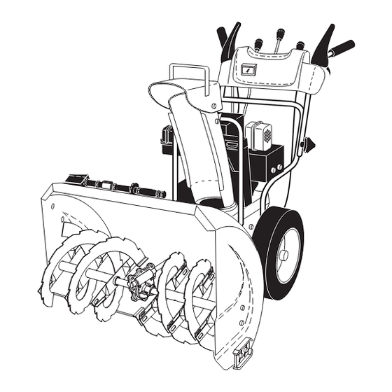
OPERATION KNOW YOUR SNOW THROWER READ THIS OWNER'S MANUAL AND ALL SAFETY RULES BEFORE OPERATING YOUR SNOW THROWER. Compare the illustrations with your snow thrower to familiarize yourself with the location of various controls and adjustments. Save this manual for future reference. These symbols may appear on your snow thrower or in literature supplied with the product. - Page 9 MUF FLER GAS O LINE FILLER CAP CHOKE CON- TROL SAFETY IGNITION ON / OFF SWITCH PRIM ER FUEL SHUT-OFF VALVE RECOIL (AUXILIARY) STARTER HANDLE NOTE: ITEMS ABOVE ARE SHOWN IN THEIR TYPICAL LOCATION ON THE ENGINE. ACTUAL LOCATION MAY VARY WITH THE ENGINE ON YOUR UNIT.
-
Page 10: How To Use Your Snow Thrower
The operation of any snow thrower can result in foreign objects thrown into the eyes, which can result in severe eye damage. Always wear safety glasses or eye shields while operating your snow thrower or performing any ad just- ments or repairs. We recommend standard safe ty glasses or a wide vision safety mask worn over spectacles. - Page 11 TO THROW SNOW (See Fig. 14) The auger rotation is controlled by the auger control lever located on the right side handle. • Squeeze auger control lever to handle to engage the auger and throw snow. • Release the auger control lever to stop throwing snow. AUGER CONTROL LEVER...
-
Page 12: Before Starting The Engine
TO ADJUST SKID PLATES (See Fig. 18) NOTE: The wrench provided in your parts bag may be used to adjust the skid plates. Skid plates are located on each side of the auger housing and adjust the clearance between the scraper bar and the ground surface. -
Page 13: Cold Start - Electric Starter
TO START ENGINE • Be sure fuel shut-off valve is in the “OPEN” position. Your snow thrower engine is equipped with both a 120 Volt A.C. electric starter and a recoil starter. The electric starter is equipped with a three-wire power cord and plug and is designed to operate on 120 Volt A.C. -
Page 14: Before Each Use
GENERAL REC OM MEN DA TIONS The warranty on this snow thrower does not cover items that have been sub ject ed to operator abuse or negligence. To receive full value from the warranty, operator must maintain snow thrower as in struct ed in this manual. Some ad just ments will need to be made periodically to properly maintain your snow thrower. - Page 15 BELTS Check belts for deterioration and wear after every 50 hours of operation and replace if necessary. The belts are not ad just able. Replace belts if they begin to slip from wear. (See “TO REMOVE BELT COVER” in the Service and Adjustments section of this manual).
-
Page 16: Service And Adjustments
SERVICE AND ADJUSTMENTS WARNING: To avoid serious injury, before performing any service or ad just ments: 1. Be sure the on/off switch is in the OFF position. 2. Remove safety ignition key. 3. Make sure the augers and all mov ing parts have completely stopped. -
Page 17: To Replace Belts
SERVICE AND ADJUSTMENTS TO REPLACE BELTS (See Fig. 22) The auger and traction drive belts are not adjustable. If the belts are damaged or begin to slip from wear, they should be replaced. It is recommended that the belt(s) be replaced by a service center/department. - Page 18 SERVICE AND ADJUSTMENTS TO REMOVE WHEELS (See Fig. 23) • Remove the klik pin and remove wheel from axle. IMPORTANT: When installing wheel, be sure to use the axle hole closest to the end of the shaft – do not use the hole in the wheel hub (if equipped).
-
Page 19: Storage
Immediately prepare your snow thrower for storage at the end of the season or if the unit will not be used for 30 days or more. WARNING: Never store the snow thrower with gaso line in the tank in side a build ing where fumes may reach an open flame, spark or pilot light as on a fur nace, water heater, clothes dryer or... -
Page 20: Troubleshooting
TROUBLESHOOTING See appropriate section in manual unless directed to an authorized service center/department. PROBLEM CAUSE Does not start 1. Fuel shut-off valve (if so equipped) in OFF position. 2. Safety ignition key is not inserted. 3. Out of fuel. 4. Throttle in STOP position (or ON/OFF switch is OFF). - Page 21 AUGER HOUSING / IMPELLER ASSEMBLY NOTE: All component dimensions given in U.S. inches. IMPORTANT: Use only Original Equipment Manufacturer (O.E.M.) replacement parts. Failure to do so could be hazardous, damage your snow thrower and void your warranty. 3 (5x) 4 (5x) 01.07.001-A 01.07.017-A PART...
- Page 22 AUGER HOUSING / IMPELLER ASSEMBLY NOTE: All component dimensions given in U.S. inches. IMPORTANT: Use only Original Equipment Manufacturer (O.E.M.) replacement parts. Failure to do so could be hazardous, damage your snow thrower and void your warranty. 01.07.026-D 2 (EXPLODED) 1 inch = 25.4 mm...
- Page 23 AUGER HOUSING / IMPELLER ASSEMBLY NOTE: All component dimensions given in U.S. inches. IMPORTANT: Use only Original Equipment Manufacturer (O.E.M.) replacement parts. Failure to do so could be hazardous, damage your snow thrower and void your warranty. PART DESCRIPTION 532 43 57-75 IMPELLER 532 42 71-48 GEARBOX ASSEMBLY...
- Page 24 AUGER HOUSING / IMPELLER ASSEMBLY 01.11.002-B NOTE: All component dimensions given in U.S. inches. IMPORTANT: Use only Original Equipment Manufacturer (O.E.M.) replacement parts. Failure to do so could be hazardous, damage your snow thrower and void your warranty. 01.07.029-A PART DESCRIPTION 532 43 27-65 PLASTIC RETAINER...
- Page 25 CONTROL PANEL / CHUTE PART DESCRIPTION 532 43 57-91 CHUTE WELDMENT 532 18 41-13 DEFLECTOR WELDMENT 532 42 11-63 DEFLECTOR CONTROL AS- SEMBLY 532 42 03-25 DEFLECTOR SEAL 532 41 42-80 KNOB BLACK 532 12 84-15 POP RIVET 817 50 10-10 SCREW 10-24 X .625 532 43 03-24 CHUTE SNOW SHIELD...
- Page 26 CONTROL PANEL / CHUTE PART DESCRIPTION 532 42 82-74 LEVER/CABLE ROTATOR ASSEMBLY 817 50 10-10 SCREW 10-24 X .625 532 42 06-78 ROTATOR HEAD 532 42 28-23 ROTATOR PIVOT BRACKET 532 42 06-75 PULLEY PIVOT 532 42 82-75 CABLE ASSEMBLY ADJUSTABLE GRAY 532 42 83-11 CABLE ASSEMBLY HEAT SHIELD GRAY NOTES:...
- Page 27 HANDLES 01.05.014-A NOTE: All component dimensions given in U.S. inches. IMPORTANT: Use only Original Equipment Manufacturer (O.E.M.) replacement parts. Failure to do so could be hazardous, damage your snow thrower and void your warranty. 01.08.010-A PART DESCRIPTION 532 42 17-08 PLOW HANDLE LH 532 42 17-09 PLOW HANDLE RH...
- Page 28 HANDLES NOTE: All component dimensions given in U.S. inches. IMPORTANT: Use only Original Equipment Manufacturer (O.E.M.) replacement parts. Failure to do so could be hazardous, damage your snow thrower and void your warranty. 01.10.043-A 01.08.007-B PART DESCRIPTION 532 42 13-82 CONSOLE PANEL GRAY 532 42 14-48 HEADLIGHT BEZEL GRAY...
- Page 29 HANDLES NOTE: All component dimensions given in U.S. inches. IMPORTANT: Use only Original Equipment Manufacturer (O.E.M.) replacement parts. Failure to do so could be hazardous, damage your snow thrower and void your warranty. 01.12.001-E PART DESCRIPTION 532 18 04-80 IMPELLER ROD ASSEMBLY 532 40 57-40 TRACTION ROD ASSEMBLY 532 18 04-45...
- Page 30 HANDLES NOTE: All component dimensions given in U.S. inches. IMPORTANT: Use only Original Equipment Manufacturer (O.E.M.) replacement parts. Failure to do so could be hazardous, damage your snow thrower and void your warranty. 01.08.012-C PART DESCRIPTION 532 43 58-04 CONTROL PANEL 532 42 91-50 CONTROL LEVER LH 532 42 91-51...
- Page 31 DRIVE 01.03.001-A NOTE: All component dimensions given in U.S. inches. IMPORTANT: Use only Original Equipment Manufacturer (O.E.M.) replacement parts. Failure to do so could be hazardous, damage your snow thrower and void your warranty. PART DESCRIPTION 532 40 49-23 (assy of 1a,1b) AXLE ASSEMBLY 532 40 43-07 AXLE SHAFT 532 18 42-06...
- Page 32 DRIVE PART DESCRIPTION 817 49 05-08 BOLT 5/16-18 X .500 532 75 11-53 NUT 5/16-18 532 18 00-17 FLANGE BEARING 873 93 05-00 NUT 5/16-18 532 43 57-89 RUBBER WHEEL PLATE 532 17 98-31 RUBBER WHEEL RING 532 17 86-13 RUBBER WHEEL HUB 874 76 05-14 BOLT 5/16-18 X .875...
- Page 33 DRIVE PART DESCRIPTION 532 19 88-75 SPEED SELECTOR HEAD ASSEMBLY 817 50 10-10 SCREW 10-24 X .625 532 19 77-63 DRIVE PLATE WELDMENT 532 19 77-64 HEX SHAFT 532 17 53-44 TRUNNION BEARING ASSEMBLY 812 00 00-12 RETAINER 872 27 05-05 CARRIAGE BOLT 5/16-18 X .625 532 18 89-09 FLANGE BEARING...
- Page 34 CHASSIS / ENGINE / PULLEYS 01.01.004-A NOTE: All component dimensions given in U.S. inches. IMPORTANT: Use only Original Equipment Manufacturer (O.E.M.) replacement parts. Failure to do so could be hazardous, damage your snow thrower and void your warranty. 01.00.033-A 01.21.013-B PART DESCRIPTION 532 43 60-70...
- Page 35 CHASSIS / ENGINE / PULLEYS PART DESCRIPTION 532 40 80-07 IMPELLER BELT 532 41 97-44 TRACTION BELT 532 43 58-02 IDLER ARM BRACKET 532 18 05-23 IDLER PULLEY 532 42 65-89 NUT 5/16-18 874 78 05-24 SCREW 5/16-18 X 1 .50 532 43 58-01 IDLER BRACKET 532 42 88-67...
-
Page 36: Repair Parts
WHEELS 01.06.009-A 01.15.002-D NOTE: All component dimensions given in U.S. inches. IMPORTANT: Use only Original Equipment Manufacturer (O.E.M.) replacement parts. Failure to do so could be hazardous, damage your snow thrower and void your warranty. PART 532 43 62-53 532 43 62-54 PART 532 43 58-27 532 43 58-26... - Page 37 WHEELS 01.15.001-B NOTE: All component dimensions given in U.S. inches. IMPORTANT: Use only Original Equipment Manufacturer (O.E.M.) replacement parts. Failure to do so could be hazardous, damage your snow thrower and void your warranty. PART DESCRIPTION 532 40 51-61 COVER 532 18 44-71 SHOULDER SCREW 812 00 00-45...
- Page 38 BAG OF PARTS 01.14.003-B 01.14.009-A NOTE: All component dimensions given in U.S. inches. IMPORTANT: Use only Original Equipment Manufacturer (O.E.M.) replacement parts. Failure to do so could be hazardous, damage your snow thrower and void your warranty. 01.14.012-A PART DESCRIPTION 532 19 85-63 POWER CORD 532 16 96-75...
- Page 39 DECALS NOTE: All component dimensions given in U.S. inches. IMPORTANT: Use only Original Equipment Manufacturer (O.E.M.) replacement parts. Failure to do so could be hazardous, damage your snow thrower and void your warranty. PART DESCRIPTION 532 18 10-37 DECAL, DANGER 532 18 10-35 DECAL, DANGER, DEFLECTOR 532 18 10-42...
-
Page 40: Warranty
(e.g., engines and transmissions) are excluded from coverage, and other limitations apply, as described in this document. Husqvarna will repair or replace at its discretion, any defective product or part covered by the Limited Warranty, free of charge at any authorized Husqvarna Servicing Dealer/Center using original OEM Husqvarna replacement parts, subject to the limitations and exclusions described below. - Page 41 Husqvarna unit to an authorized Husqvarna Servicing Dealer/Center and arrange for pick-up or return of your unit after the repairs have been made. If you do not know the location of your nearest authorized Husqvarna Servicing Dealer, call Husqvarna, at 1-800-487-5951 during the hours of 8:00 AM to 8:00 PM Eastern Standard Time, or visit www.husqvarna.com.
- Page 42 ** See reference 1 (b) of the warranty statement. RZ - Two (2) Year Consumer warranty, parts & labor, with Hydro-Gear Distributor network. EZ - One (1) Year Commercial warranty, parts & labor, with Husqvarna. Two (2) Year Consumer warranty, parts & labor, with Hydro-Gear Distributor network.
- Page 43 ** See reference 1 (b) of the warranty statement. RZ - Two (2) Year Consumer warranty, parts & labor, with Hydro-Gear Distributor network. EZ - One (1) Year Commercial warranty, parts & labor, with Husqvarna. Two (2) Year Consumer warranty, parts & labor, with Hydro-Gear Distributor network.
- Page 44 532 43 56-49 08.13.10 AP Printed in the U.S.A.
Need help?
Do you have a question about the 96193005500 and is the answer not in the manual?
Questions and answers