Husqvarna 1130 SBE OV Operator's Manual
Hide thumbs
Also See for 1130 SBE OV:
- Owner's manual (32 pages) ,
- Illustrated parts list (14 pages) ,
- Owner's manual (32 pages)

Related Manuals for Husqvarna 1130 SBE OV


Summary of Contents for Husqvarna 1130 SBE OV
- Page 1 2008-01 Operator's Manual O0802024 Snow Thrower 1130 SBE OV 96193002400 Operator's Manual...
-
Page 2: Safety Rules
IMPORTANT Safe Operation Practices for Walk-Behind Snow Throwers This snow thrower is capable of amputating hands and feet and throwing objects. Failure to observe the following safety instructions could result in serious injury. WARNING: Snow throwers have ex- Look for this symbol to point out im- posed rotating parts, which can cause portant safety precautions. -
Page 3: Table Of Contents
6. When cleaning, repairing or inspecting the snow thrower, Clearing a Clogged Discharge Chute stop the engine and make certain the collector/impeller Hand contact with the rotating impeller inside the discharge and all moving parts have stopped. Disconnect the chute is the most common cause of injury associated with spark plug wire and keep the wire away from the plug snow throwers. - Page 4 PARTS PACKED SEPARATELY IN CARTON...
-
Page 5: Assembly / Pre-Operation
ASSEMBLY / PRE-OPERATION Read these instructions and this manual in its entirety before you attempt to assemble or operate your new snow thrower. Reading the entire manual will familiarize you with the unit, which will assist you in assembly, operation and maintenance of the product. Your new snow thrower has been as sembled at the factory with the ex ception of those parts left unassembled for shipping purposes. - Page 6 ASSEMBLY / PRE-OPERATION INSTALL AUGER CONTROL ROD (See Figs. 5 and 6) INSTALL TRACTION DRIVE CONTROL ROD (See Figs. 3 and 4) The auger control rod has the short loop on the end of the spring as shown. The traction drive control rod has the long loop on the end of the spring as shown.
- Page 7 ASSEMBLY / PRE-OPERATION INSTALL CHUTE DEFLECTOR REMOTE CONTROL INSTALL DISCHARGE CHUTE / CHUTE ROTATOR (See Figs. 8 and 9) HEAD (See Fig. 7) 1. Install remote cable bracket to discharge chute with NOTE: The multi-wrench provided in your parts bag may 5/16-18 carriage bolt and 5/16-18 locknut as shown.
-
Page 8: Operation
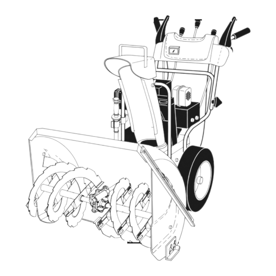
OPERATION KNOW YOUR SNOW THROWER READ THIS OWNER'S MANUAL AND ALL SAFETY RULES BEFORE OPERATING YOUR SNOW THROWER. Compare the illustrations with your snow thrower to familiarize yourself with the location of various controls and adjustments. Save this manual for future reference. These symbols may appear on your snow thrower or in literature supplied with the product. - Page 9 OPERATION SPARK ENGINE OIL CAP AUGER DISCHARGE CHUTE CONTROL LEVER PLUG WITH DIPSTICK CONTROL SAFETY LEVER DEFLECTOR REMOTE DRIVE SPEED IGNITION CONTROL LEVER CONTROL LEVER GASOLINE FILLER TRACTION CHUTE CHOKE DRIVE DEFLECTOR CON- CONTROL TROL LEVER FUEL SHUT-OFF VALVE LH TURN TRIGGER THROTTLE / ENGINE...
- Page 10 OPERATION The operation of any snow thrower can result in foreign objects thrown into the eyes, which can result in severe eye damage. Always wear safety glasses or eye shields while operating FULL your snow thrower or performing any ad just- ments or repairs.
- Page 11 OPERATION SPEED and DIRECTION are controlled by the drive speed control lever. AUGER CONTROL • Move speed control lever to de sired po sition AFTER LEVER engaging the trac tion drive control lever. CAUTION: Do not move speed con trol le ver unless engine is running.
-
Page 12: Before Starting The Engine
OPERATION NOTE: It is not recommended to operate the snow thrower BEFORE STARTING THE ENGINE over gravel or rocky surfaces. Objects such as gravel, rocks CHECK ENGINE OIL LEVEL (See Fig. 21) or other debris, can easily be picked up and thrown by the impeller, which can cause serious personal injury, property The engine on your snow thrower has been shipped, from damage or damage to the snow thrower. -
Page 13: Snow Throwing Tips
OPERATION 6. When the engine starts, release the recoil starter han dle TO START ENGINE and slowly move the choke control to the OFF position. • Be sure fuel shut-off valve is in the OPEN position. Allow the engine to warm up for a few minutes. Engine will Your snow thrower engine is equipped with both a 120 Volt not develop full power until it has reached normal operat- A.C. -
Page 14: Maintenance
MAINTENANCE GENERAL REC OMMENDA TIONS LUBRICATION CHART The warranty on this snow thrower does not cover items that have been sub jected to operator abuse or negligence. To ➀ SAE 30 Motor Oil receive full value from the warranty, operator must maintain ➁... - Page 15 MAINTENANCE SNOW THROWER after each fi ve (5) hours of continuous use. Tighten oil fi ll cap / dipstick securely each time you check the oil level. Always observe safety rules when performing main tenance. TO CHANGE ENGINE OIL TIRES Determine temperature range anticipated before next oil •...
-
Page 16: Service And Adjustments
SERVICE AND ADJUSTMENTS To replace the capscrew/shear bolts: WARNING: To avoid serious injury, before per- 1. Disengage all controls and move throttle control to forming any service or ad justments: STOP position. Wait for all moving parts to stop. 1. Be sure throttle is in STOP position. 2. -
Page 17: Service And Adjustments
SERVICE AND ADJUSTMENTS TO REPLACE BELTS (See Fig. 24) 6. REMOVE AUGER BELT from around pulley. The auger and traction drive belts are not adjustable. If the belts are damaged or begin to slip from wear, they should 7. Remove traction drive belt from around pulleys. be replaced. -
Page 18: Storage
TO REMOVE WHEELS (See Fig. 25) ENGINE • Remove the bolt and nut; remove wheel from axle. See engine manual. NOTE: To seal punctures or prevent fl at tires due to slow CARBURETOR leaks, tire sealant may be purchased from your local parts Your carburetor is not adjustable. -
Page 19: Troubleshooting
TROUBLESHOOTING See appropriate section in manual unless directed to a qualifi ed service center. PROBLEM CAUSE CORRECTION Does not start 1. Fuel shut-off valve (if so 1. Turn fuel shut-off valve to OPEN position. equipped) in OFF position. 2. Safety ignition key 2. -
Page 20: Repair Parts
REPAIR PARTS AUGER HOUSING / IMPELLER ASSEMBLY SNOW THROWER - MODEL NUMBER 1130SBE-OV (96193002400) - Page 21 REPAIR PARTS AUGER HOUSING / IMPELLER ASSEMBLY SNOW THROWER - MODEL NUMBER 1130SBE-OV (96193002400) KEY PART KEY PART DESCRIPTION DESCRIPTION 532 18 25-16 Bar, Weight 532 18 79-25 Bearing 532 75 11-53 Nut, Hex 5/16-18 532 40 77-22 Auger Assembly, RH 872 11 05-10 Bolt, Carriage 5/16-18 x 1-1/4 532 40 77-23 Auger Assembly, LH 532 19 10-79 Pulley, Impeller...
- Page 22 REPAIR PARTS CONTROL PANEL / DISCHARGE CHUTE SNOW THROWER - MODEL NUMBER 1130SBE-OV (96193002400)
- Page 23 REPAIR PARTS CONTROL PANEL / DISCHARGE CHUTE SNOW THROWER - MODEL NUMBER 1130SBE-OV (96193002400) KEY PART DESCRIPTION 532 41 42-80 Knob, Lever 817 50 10-10 Screw #10-24 x 5/8 532 19 84-75 Control Assembly, Defl ector 873 80 06-00 Nut, Lock 3/8-16 819 13 13-16 Washer, Flat 3/8 532 40 49-74 Control Assembly, Chute Rotater 532 41 54-89 Support, Pivot...
- Page 24 REPAIR PARTS HANDLES SNOW THROWER - MODEL NUMBER 1130SBE-OV (96193002400)
- Page 25 REPAIR PARTS HANDLES SNOW THROWER - MODEL NUMBER 1130SBE-OV (96193002400) KEY PART DESCRIPTION 532 41 55-42 Lever, Auger Control, RH 532 41 55-41 Lever, Traction Drive Control, LH 532 16 96-75 Retainer, Hairpin 817 06 04-08 Screw, Hex Head 532 41 26-77 Rod, Interlock 532 19 95-76 Arm, Impeller Rod 532 41 55-46 Arm, Traction Rod 532 41 55-39 Panel, Control...
- Page 26 REPAIR PARTS DRIVE SNOW THROWER - MODEL NUMBER 1130SBE-OV (96193002400)
- Page 27 REPAIR PARTS DRIVE SNOW THROWER - MODEL NUMBER 1130SBE-OV (96193002400) KEY PART DESCRIPTION 817 49 05-08 Screw, Hex Head 5/16-18 x 3/4 812 00 00-04 Ring, Retaining 819 19 13-16 Washer, Flat 532 41 32-71 Plate, Rod Alignment 532 40 21-95 Bearing, Axle 873 80 06-00 Nut, Hex, Centerlock 3/8-16 532 41 11-95 Transmission Assembly 532 41 12-03 Control Rod, Steering...
- Page 28 REPAIR PARTS CHASSIS / ENGINE / PULLEYS SNOW THROWER - MODEL NUMBER 1130SBE-OV (96193002400) 23 59...
- Page 29 REPAIR PARTS CHASSIS / ENGINE / PULLEYS SNOW THROWER - MODEL NUMBER 1130SBE-OV (96193002400) KEY PART DESCRIPTION - - - Engine, Tecumseh, Model Number OH318SA (For engine service and replacement parts, call Tecumseh Products at 1-800-558-5402) 532 15 54-15 Washer, Flat 532 16 67-85 Nut, Jam, Lock 5/16-18 532 17 53-30 Pin, Idler Pivot 532 41 12-18 Belt, Traction Variator...
- Page 30 REPAIR PARTS WHEELS / DECALS SNOW THROWER - MODEL NUMBER 1130SBE-OV (96193002400)
- Page 31 532 41 90-47 Decal, Husqvarna 532 18 10-35 Decal, Danger, Defl ector 532 18 10-42 Decal, Danger 532 41 90-48 Decal, Husqvarna, 1130SBE-OV 532 18 10-33 Decal, Instruction 532 41 54-75 Decal, Speed Control 532 18 37-30 Decal, Remote Defl ector...
-
Page 32: Warranty
Rental Warranty: 90 days on all applicable professional equipment reference warranty time period charts mailed to Husqvarna Forest & Garden Company. This card should be mailed within ten (10) days from the date of purchase located in the back of the Retailer Warranty Policy & Procedure Manual.
Need help?
Do you have a question about the 1130 SBE OV and is the answer not in the manual?
Questions and answers