Table of Contents
Advertisement
Advertisement
Table of Contents

Subscribe to Our Youtube Channel
Related Manuals for Sony HSC-300


Summary of Contents for Sony HSC-300
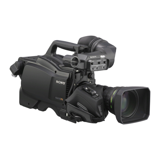
- Page 1 HD COLOR CAMERA HSC-300 The supplied CD-ROM includes Operation Manual for the HSC-300 HD Color Camera (English, French, German, Italian, and Spanish versions) in PDF format. For more details, see “Using the CD-ROM Manuals” on page 8. OPERATION MANUAL [English]...
- Page 2 (urbain extérieur) et E4 (environnement EMC contrôlé, ex. expense. studio de télévision). You are cautioned that any changes or modifications not Le fabricant de ce produit est Sony Corporation, 1-7-1 Konan, expressly approved in this manual could void your authority to Minato-ku, Tokyo, Japon. operate this equipment.
-
Page 3: Table Of Contents
Maße industrieller Bereich), E3 (Stadtbereich im Freien) und Connector panel ............. 11 E4 (kontrollierter EMV-Bereich, z.B. Fernsehstudio). Installation ............... 13 Der Hersteller dieses Produkts ist Sony Corporation, 1-7-1 Connecting a Camera Control Unit (CCU) ....13 Konan, Minato-ku, Tokyo, Japan. Attaching a Lens ............13 Der autorisierte Repräsentant für EMV und Produktsicherheit... -
Page 4: Overview
1) An HSC-300 and HXCU-100 can be connected if both units are of A low-repulsion shoulder pad (position fixed) is available as an version 1.10 or later. - Page 5 2) Center marker: A cross-shaped marker which indicates the center “Memory Stick.” of the viewfinder screen 1) “Memory Stick” and are trademarks of Sony Wide variety of viewfinder display options Corporation. Along with items such as operation messages, a zebra...
-
Page 6: System Configuration
Note figures. Production of some of the peripherals and related devices shown in the figures has been discontinued. For advice on choosing devices, please contact your Sony dealer or a Sony sales representative. Standalone operation example RCP-1000-series Remote Control Panel... -
Page 7: System Operation Example (Two Cameras With Camera Control Units)
Panel DC 12 V (Max. 5A) a) Enabled only when an HSCU-300 is connected. An HSC-300 and HXCU-100 can be connected if both units b) Supplied with the HDVF-550/C550W/C730W, Part No.: A-7612-405-E are of version 1.10 or later. c) 900 m (2953 ft) when an HSCU-300 is connected or 600 m (1969 ft) when an e) Supplied with the HDLA1500/1505, Part No.: A-1128-405-A... -
Page 8: Using The Cd-Rom Manuals
Note c Accessory shoe If you have lost or damaged the CD-ROM, you can purchase To attach an accessory using a 1/4-inch screw. a new one to replace it. Contact your Sony service d Viewfinder shoe representative. Mount a viewfinder. -
Page 9: Front Left
i Assignable buttons o STATUS/CANCEL switch You can assign a function to the upper button by using STATUS: To display status information of this camera in the ASSIGNABLE 1 and the lower button with ASSIGNABLE 2 on viewfinder when no menu is displayed with the DISPLAY/ the <SWITCH ASSIGN1>... -
Page 10: Rear
b Shoulder strap fitting post BLK: To automatically adjust black balance. For details, see “Adjusting the Black Balance and White c Operation panel (See “Operation panel”.) Balance” (page 17). d Camera Control Unit (CCU) connector (triax g INTERCOM LEVEL control connector) To adjust the intercom/earphone volume level. -
Page 11: Connector Panel
g LEVEL switch on the viewfinder screen while holding the RET button pressed. REAR: The intercom audio listening level is adjusted with the ENG or PROD control on this panel. Note FRONT: The levels adjusted on the rear panel can be totally The RET 1 button has priority over the RET (2/3/4) button if adjusted with the INTERCOM LEVEL control on the front. - Page 12 Notes Notes • Even when a BB signal is used for the external sync signal, • As SDI OUT is set to PWR SAVE at the factory, an SDI no subcarrier phase-lock function is available for the VBS signal is not output. Set it to ACTIVE on the POWER SAVE output signal.
-
Page 13: Installation
Adjust the length by pulling down the end of the belt. Installation Connecting a Camera Control Unit (CCU) When operating the camera in a system with a CCU, connect between the CCU connector of the camera and the CAMERA connector of the CCU, using a triax cable. When required, secure the cable, using the supplied cable clamp belt. -
Page 14: Attaching A Viewfinder
Status displays in the viewfinder Attaching a Viewfinder Besides the video image, the viewfinder can display characters and messages showing the camera settings and Caution operation status, as well as items such as a center marker or When the viewfinder is attached, do not leave the camera with safety-zone marker. -
Page 15: Attaching A Microphone
k F-value indication To attach a microphone, using a CAC-12 Indicates the lens F (iris opening) value. When attaching a long-type microphone, such as an ECM- 674/678, use an optional CAC-12 Microphone Holder. When the STATUS/CANCEL switch is set to STATUS 1 Remove the front screw-hole cover on the top then ×... -
Page 16: Adjusting The Shoulder Pad Position
Original position Tripod adaptor Adjusting the Shoulder Pad Position Platform You can shift the shoulder pad in the range of 28 mm (1 inches). This adjustment helps you get the best balance for shooting with the camera on your shoulder. To adjust 1 Raise the lever in the center of the shoulder pad to unlock the shoulder pad, 2 slide the shoulder pad backward or... -
Page 17: Preparatory Settings
To adjust the white balance Preparatory Settings Select the built-in filters according to the lighting conditions with the filter select knobs. Adjusting the Black Balance and White Balance CC filter select knob In order to maintain high picture quality when using the camera, it is necessary to set the black balance and white ND filter select knob balance appropriately for the conditions. -
Page 18: Setting The Electronic Shutter
Setting the Electronic Shutter This section explains the different modes which can be used S H U T T for the electronic shutter and gives the procedures for setting O FF W H T R E T S E L the shutter mode and shutter speed. -
Page 19: Setting The Local Time
Push on the menu control knob to shift to the next digit. Example: with 59.94i Standard mode When the date/time setting is completed, set the DISPLAY/MENU switch to OFF to exit Menu mode. 1/100 1/125 1/250 1/500 1/1000 1/2000 Adjusting the Flange Focal Length ECS mode Adjustment of the flange focal length (the distance between the lens mount attachment plane and the imaging plane) is... -
Page 20: Setting The Focus Assist Function
adjust the signal level (strength) in the range of 0 to 100% Setting the Focus Assist Function (default 25%). You can adjust the characteristics of the detail signal with Using the OPERATION menu, the assist functions for easier the menu items below: focusing on the viewfinder screen can be activated. -
Page 21: Setting The Camera Outputs
Rotate the menu control knob to align the pointer to See “Adjusting the Flange Focal Length” (page 19) for the <FOCUS ASSIST> and push on the menu control flange focal length. knob. The <FOCUS ASSIST> page is displayed. Setting the Camera Outputs <FOCUS ASSIST>... -
Page 22: Outputting A Trunk Signal
setting CHARACTER to ON on the <SDI OUT> or <TEST To output as VBS OUT> page. Menu page Item Setting To output as HD-SDI <POWER SAVE> DOWN CONVERTER ACTIVE <DOWN CONVERTER> OUTPUT SIGNAL Menu page Item Setting <TEST OUT> OUTPUT <POWER SAVE>... -
Page 23: Menus
<TOP MENU> Menus USER USER MENU CUSTOMIZE OPERATION PAINT MAINTENANCE FILE The menus displayed on the viewfinder screen enable various DIAGNOSIS settings of the camera. The following controls are used to operate the menus. To enter Menu mode, you can use the DISPLAY/MENU switch Menu Purpose either on the side or on the rear operation panel. - Page 24 To reset a changed value If the screen can be scrolled, arrows will If you press the STATUS/ CANCEL switch toward indicate the direction for scrolling. CANCEL before pushing on the menu control knob, the setting will be returned to its previous value. CONTENTS To interrupt settings 01.<VF DISPLAY>...
-
Page 25: Editing The User Menu
To add items to a page Editing the USER Menu Select USER MENU CUSTOMIZE on the TOP MENU You can select desired pages and items from the screen (page 23). OPERATION, PAINT, MAINTENANCE, FILE, and If this is the first time the USER MENU CUSTOMIZE DIAGNOSIS menus and register them to the USER menu. - Page 26 Add the items. Note You cannot insert a blank line on a page where 10 items have 1 Turn the menu control knob until the page that has the desired items appears, then push on the menu control already been registered. knob.
-
Page 27: Operation Menu
To delete a page OPERATION Menu On the EDIT PAGE screen of the USER MENU Note CUSTOMIZE menu, move the pointer to the page to be deleted and push on the menu control knob. These remarks are common for all the following menu tables. The EDIT FUNCTION screen appears. - Page 28 Page title Item Settings Page title Item Settings Page No. Page No. <'!' IND> [IND]: Activate/deactivate the '!' indication (page <VF MARKER> MARKER ON, OFF 02 (U05) 15). 03 (U06) WHITE, BLACK, DOT [NORMAL]: Specify the conditions under which CENTER ON, OFF the ‘!’...
- Page 29 Page title Item Settings Page title Item Settings Page No. Page No. <FOCUS INDICATOR ON, OFF, (EFFECT) <VF OUT> VF OUT COLOR, Y, R, G, B, ASSIST> (EFFECT): Displayed 08 (U01) (COLOR), (Y), (R), (G), 05 (U03) when EFFECT of <VF (B), (RET), (R+G), (R+B), MARKER>...
- Page 30 Page title Item Settings Page title Item Settings Page No. Page No. <SWITCH LENS VTR S/S UC model: <RECEIVE TRACKER SEPARATE, MIX ASSIGN2> Assign a function SEL2> RECEIVE SELECT OFF, RETURN1 SW, 10 (U10) to the VTR RETURN2 SW, INCOM INTERCOM - - -, LEFT, RIGHT, BOTH START/STOP...
-
Page 31: Paint Menu
Page title Item Settings PAINT Menu Page No. <GAMMA> LEVEL – R/G/B/M: 99 to 99 0 Page title Item Settings COARSE 0.35 to 0.45 to 0.90 Page No. (0.05 steps) <SW STATUS> FLARE ON, OFF TABLE STANDARD, HYPER GAMMA ON, OFF With STANDARD selected: BLK GAM ON, OFF... - Page 32 Page title Item Settings Page title Item Settings Page No. Page No. <KNEE> K POINT – <SKIN DETAIL> SKIN DTL ON, OFF R/G/B/M: 99 to 99 0 SKIN GATE ON, OFF, (MAT) K SLOPE – R/G/B/M: 99 to 99 0 (MAT): Displayed when KNEE ON, OFF...
-
Page 33: Maintenance Menu
Page title Item Settings Page title Item Settings Page No. Page No. <MULTI PHASE 0, 23, 45, 68, 90, 113, 135, <SCENE FILE> To store and read scene MATRIX> Select an axis 158, 180, 203, 225, 248, files (paint data). (angle) for which 270, 293, 315, 338 See “FILE... - Page 34 Page title Item Settings Page title Item Settings Page No. Page No. <OHB MATRIX> PHASE 0, 23, 45, 68, 90, 113, 135, <UP TALLY>* TALLY 0 to 100 50 Select an axis 158, 180, 203, 225, 248, M07 (U21) BRIGHTNESS (angle) for which 270, 293, 315, 338 *Display on...
- Page 35 Page title Item Settings Page title Item Settings Page No. Page No. <TEST OUT> OUTPUT SD-SYNC, VF, HD-SYNC, <BATTERY BEFORE END 11.5 V to 17.0 V M11 (U17) VBS, PROMPTER2 ALARM> 11.0 V to 11.5 V PROMPTER2 is enabled only when an HSCU-300 is <OTHERS 1>...
-
Page 36: File Menu
Page title Item Settings / Default FILE Menu Page No. <SCENE FILE> To store and read scene Five types of files can be used for easy adjustments of the files (paint data): camera; Operator, Reference, Scene, OHB, and Lens. When storing a file in You can store the items set with the OPERATION menu and camera memory, specify customized USER menu in the Operator file. -
Page 37: Diagnosis Menu
D03 (U22) repeated store operation Displayed only when is necessary even if the mounted in HDLA CCD is reattached.) <SERIAL NO.> MODEL HSC-300 <FILE CLEAR> PRESET Execute by ENTER. Serial No. OPERATOR REFERENCE (ALL) Execute by ENTER. 10 SEC CLEAR... -
Page 38: Appendices
Aliasing Appendices When fine patterns, stripes, or lines are shot, they may appear jagged or flicker. About digital triax transmission A powerful error-correction function is incorporated for the Precautions transmission between the camera and CCU. However, if an error occurs on long-distance transmission because of Note on laser beams external noise or for some other reason, the compensation by interpolation that partially uses the previous picture may... -
Page 39: Error Messages
MSU RPN BUSY RPN compensation was attempted using the camera menu while being operated from an external device. Consult Sony service personnel. VF RPN BUSY RPN compensation was attempted from an external device while being operated using the camera menu. -
Page 40: Specifications
• “Memory Stick Duo” is a trademark of Sony Corporation. • “Memory Stick PRO” and are trademarks of Sony Corporation. • “Memory Stick PRO Duo” is a trademark of Sony Corporation. • “MagicGate” is a trademark of Sony Corporation. “Memory Stick” Access lamp... - Page 41 8-pin (1) Note Always verify that the unit is operating properly before use. TRACKER 10-pin (1) SONY WILL NOT BE LIABLE FOR DAMAGES OF ANY Supplied accessories KIND INCLUDING, BUT NOT LIMITED TO, Operation manual (1) COMPENSATION OR REIMBURSEMENT ON ACCOUNT...
-
Page 42: Menu Tree
Menu Tree OPERATION ZEBRA (06) RECEIVE SEL3 (15) VF DISPLAY (01) ZEBRA EARPHONE RECEIVE SELECT ZEBRA1 LEVEL INTERCOM (UC model) ZOOM WIDTH ENG (CE model) DISP ZEBRA2 PROD (CE model) FOCUS CURSOR (07) PGM1 CURSOR PGM2 BOX/CROSS TRACKER 5600K H POSITION OPERATOR FILE (16) IRIS V POSITION... - Page 43 PAINT MAINTENANCE DETAIL 1 (P09) SW STATUS (P01) AUTO SETUP (M01) DETAIL FLARE AUTO BLACK LEVEL GAMMA AUTO WHITE LIMITER [M] BLK GAM AUTO LEVEL LIMITER [WHT] KNEE AUTO WHITE SHADING LIMITER [BLK] WHT CLIP AUTO BLACK SHADING CRISP DETAIL TEST LVL DEP LVL DEP...
- Page 44 FILE DIAGNOSIS TEST OUT (M11) OPERATOR FILE (F01) BOARD STATUS (D01) OUTPUT READ (MStCAM) (PWR SAVE) WRITE (CAMtMS) VBS-OUT PRESET CHARACTER STORE PRESET FILE GAIN FILE ID CHROMA CAM CODE SETUP (UC model) DATE PLD VERSION (D02) HD SYNC-OUT SCENE FILE (F02) V-PHASE 1/2/3/4/5 H-PHASE...
- Page 45 The material contained in this manual consists of information that is the property of Sony Corporation and is intended solely for use by the purchasers of the equipment described in this manual. Sony Corporation expressly prohibits the duplication of any...
- Page 46 Sony Corporation Printed in Japan HSC-300 (UC/CE) 2010.07 08 4-137-697-02(1) © 2009...
Need help?
Do you have a question about the HSC-300 and is the answer not in the manual?
Questions and answers