Sony VPL-CS7 Service Manual
Hide thumbs
Also See for VPL-CS7:
- Quick reference manual (88 pages) ,
- Operating instructions manual (54 pages) ,
- Specifications (2 pages)
Table of Contents
Advertisement
Advertisement
Table of Contents

Related Manuals for Sony VPL-CS7


Summary of Contents for Sony VPL-CS7
- Page 1 DATA PROJECTOR VPL-CS7 VPL-ES2 REMOTE COMMANDER RM-PJ2 SERVICE MANUAL 1st Edition...
- Page 2 LES SCHÉMAS DE PRINCIPE, LES VUES EXPLOSÉES ET LES CRITICAL TO SAFE OPERATION. REPLACE THESE COMPO- LISTES DE PIECES SONT D’UNE IMPORTANCE CRITIQUE NENTS WITH SONY PARTS WHOSE PART NUMBERS APPEAR POUR LA SÉCURITÉ DU FONCTIONNEMENT. NE LES AS SHOWN IN THIS MANUAL OR IN SUPPLEMENTS PUB- REMPLACER QUE PAR DES COMPOSANTS SONY DONT LE LISHED BY SONY.
- Page 3 Kommunen. Entladen sind Batterien in der Regel dann, wenn das Gerät abschaltet und signalisiert “Batterie leer” oder nach längerer Gebrauchsdauer der Batterien “nicht mehr einwandfrei funktioniert”. Um sicherzugehen, kleben Sie die Batteriepole z.B. mit einem Klebestreifen ab oder geben Sie die Batterien einzeln in einen Plastikbeutel. VPL-CS7/ES2...
-
Page 5: Table Of Contents
White Balance Adjustment ............... 2-14 2-5-1. HIGH Mode of INPUT-A ............2-14 2-5-2. LOW Mode of INPUT-A ............2-14 2-5-3. HIGH Mode of VIDEO ............2-14 2-5-4. LOW Mode of VIDEO ............. 2-14 2-6. Memory Structure ..................2-15 3. Semiconductors VPL-CS7/ES2... - Page 6 6. Schematic Diagrams C ........................6-2 G ........................ 6-15 H ........................ 6-17 NR ......................6-18 QA (VPL-ES2) ..................6-18 Q (VPL-CS7) .................... 6-18 SA ......................6-19 S ......................... 6-19 V ........................ 6-19 Frame Wiring .................... 6-20 7. Board Layouts C ........................7-2 G ........................
-
Page 7: Service Overview
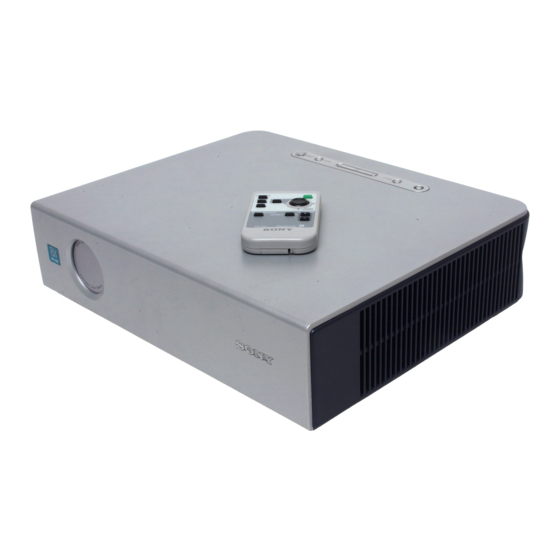
Section 1 Service Overview 1-1. Appearance Figure VPL-CS7/ES2 RM-PJ2 1-2. Board Locations Q (For VPL-CS7) QA (For VPL-ES2) Lamp power supply VPL-CS7/ES2... -
Page 8: Disassembly
(+BV3 x 70) 1-3-2. H Board . Remove the top panel assembly. (Refer to 1-3-1.) 3 Top panel 1 Five claws 7 Button (H) 8 H board 4 Flat connector assembly CN10 6 Holder (H) 2 Two dowels 5 Two claws VPL-CS7/ES2... -
Page 9: C Board
8 Hexagon screws Side panel shaft 7 Screw 9 Bracket (C) (+PSW3 x 8) C board 0 Fuse connector assembly CN806 CN811 !- C board CN809 CN815 6 Remove the C board in the direction of the arrow C. VPL-CS7/ES2... -
Page 10: Lens Gear
3 Remove the four claws 4 Dowel in the direction of the arrow B. Side panel assembly Fan holder 2 Remove the side panel assembly in the direction of the arrow A. VPL-CS7/ES2... -
Page 11: Fan (60 Mm) And D.c. Fan (70 Mm)
1 Two grooves 1-3-7. Lamp House . Remove the fan holder. (Refer to 1-3-5.) 4 Screw 2 Two screws (+BTP3 x 10) (+BTP3 x 10) 1 Remove the harness. 3 Lamp power supply 5 Lamp house CN807 CN810 C board VPL-CS7/ES2... -
Page 12: Optics Block Assembly
(+PTP2 x 8) 1 Two precision screws (+B2 x 5) 6 Pre radiation polarizer 5 Radiation polarizer (G) assembly (R) assembly 7 Radiation polarizer (G) assembly 9 Radiation polarizer (B) assembly 2 Prism block assembly 8 Pre radiation polarizer (B) assembly VPL-CS7/ES2... -
Page 13: Incidence Polarizer (R), (G), (B)
. Remove the optics unit assembly. (Refer to 1-3-8.) . Remove the prism block assembly. (Refer to 1-3-9.) 1 Six screws (+BTP3 x 10) 2 Unit cover 3 Incidence polarizer (R) assembly 4 Incidence polarizer (G) assembly 5 Incidence polarizer (B) assembly VPL-CS7/ES2... -
Page 14: Side Panel Assembly-1
C board 3 Open the side panel assembly in the direction of the arrow A. Cover (G) 5 Screw (+PSW3 x 8) Cover (B2) 6 Cover (G), Sheet (G) Cover (B) G board Sheet (G) G board C board VPL-CS7/ES2... -
Page 15: Side Panel Assembly-2
1 Open the side panel assembly in the direction of the arrow AB . 3 Sheet (NR2) 4 NR board CN80 5 L board CN70 Claw Two claws 7 Sheet (SP) 8 Speaker assembly 9 Side panel assembly 6 Speaker bracket VPL-CS7/ES2... -
Page 16: G Board
. Remove the cover (G), sheet (G). (Refer to 1-3-11) . Remove the G board. (Refer to 1-3-13.) 3 Sheet (B) 2 Two screws (+PSW3 x 8) 1 Two screws (+BTP3 x 10) 4 Lamp power supply C board 1-10 VPL-CS7/ES2... -
Page 17: Fan (Sirocco/For Lamp)
. Remove the G board. (Refer to 1-3-13.) 1 Two screws (+BTP3 x10) 5 Remove the D.C. fan (Sirocco/For lamp) in the direction of the arrow. 4 Loosen the screw. 2 Fan bracket 6 D.C. fan (Sirocco/For lamp) Fan holder C board 3 Two dowels 1-11 VPL-CS7/ES2... -
Page 18: Fan (Sirocco)
(+BTP3 x 10) C board 1 Remove the fuse connector assembly. 6 Fan holder 5 Remove the fan holder in the direction of the arrow. Dowel 9 D.C. fan (Sirocco) 8 Two dowels 7 Remove the harness. D.C. fan (Sirocco) 1-12 VPL-CS7/ES2... -
Page 19: Adjuster Block Assembly
4 Optics block assembly . Remove the optics block assembly. (Refer to 1-3-8.) 5 Three screws (+BTP3 x 10) 9 Adjuster block assembly 7 Dowel 6 Dowel 8 Remove the adjuster block assembly in the direction of the arrow. 1-13 VPL-CS7/ES2... -
Page 20: Note On Power Cord
H05VV-F H05VV-F N13237/CO-228 VCTF Rated Voltage/Current 10A/125V 10A/125V 10A/250V 10A/250V 10A/250V 7A/125V Safety approval UL/CSA UL/CSA DENAN Cord length (max.) 4.5m (14 feet 9 inches) – (1) Use an appropriate rating plug which is applied to local regulations. 1-14 VPL-CS7/ES2... -
Page 21: Electrical Adjustments
2-1-2. Opt Unit Adjustment Procedure 1. Let the VPL-CS7/ES2 show the ALL WHITE screen. 1. Rotate the lens focus and zoom in the fully clockwise 2. Adjust the B-channel illumination adjustment mirror positions. Lock the lens gear in the direction shown in so that the yellow frame must not appear in any of top, Fig. -
Page 22: How To Enter The Factory Mode
ZOOM and FOCUS are moved to their the FLAT FIELD 100 IRE signal to the input connec- very ends. tor. Leave the VPL-CS7/ES2 with POWER ON for 10 minutes or longer for aging. 2. Enter the Factory Mode. Enter the Device Adjust... - Page 23 VPL-CS7/ES2...
- Page 24 VPL-CS7/ES2...
- Page 25 VPL-CS7/ES2...
- Page 26 VPL-CS7/ES2...
- Page 27 VPL-CS7/ES2...
- Page 28 VPL-CS7/ES2...
- Page 29 VPL-CS7/ES2...
- Page 30 2-10 VPL-CS7/ES2...
- Page 31 2-11 VPL-CS7/ES2...
- Page 32 2-12 VPL-CS7/ES2...
-
Page 33: Service Know-How
8. Enter the Other MENU and let the message “38 Other/ X TILT xxxx” (xxxx is any value) on screen. 9. Enter the X TILT value while the VPL-CS7/ES2 is set in the horizontal position, in “35 Other/TILT CO”. 10. Turn the VPL-CS7/ES2 so that it faces upward in the vertical position. -
Page 34: White Balance Adjustment
INPUT-A LOW mode, adjust the BIAS R and BIAS B for the same value as those of the INPUT-A HIGH 1. Input the 80 IRE flat field signal to the INPUT-A mode. connector. 4. Press the MEMORY key for saving the adjustment value. 2-14 VPL-CS7/ES2... -
Page 35: Memory Structure
Standard Standard Game Game Video Video Living Living Cinema Cinema Presentation Presentation Dynamic Dynamic Standard Standard Game Game Input-A Input-A Living Living Cinema Cinema Presentation Presentation Dynamic Dynamic Standard Standard Game Game Living Living Cinema Cinema Presentation Presentation 2-15 VPL-CS7/ES2... - Page 36 The adjustment items(W/B, Device Adjust) that can be adjusted in the Service Mode or in the Factory mode, are memorized in the NVM at the time when the user performs adjustment and performs the memory operation. Note that the factory adjustment data will be lost at this moment. 2-16 VPL-CS7/ES2...
-
Page 37: Semiconductors
Section 3 Semiconductors 24LC21AT/SN BA00ASFP-E2 CXD3536R MCZ3001U CY25023SZC-1T HN58X24256FPIZ M24C64-WMN6T(B) SI4403DY-T1 SN75453BPS SN75453BPSR TOP VIEW TOP VIEW ST24FC21M6TR 32pin SOP 176pin QFP TC7WH125FK(TE85R) 1 : IN 2 : GND TC7WH34FU(TE12R) MX29LV800ATTC-70G- HD64F2376VFQ33V 3 : OUT UPC393G2 751PW100 UPC393G2-E2 BA00AST BA00AST-V5 TOP VIEW TOP VIEW 144pin QFP... - Page 38 Transistor, Diode, LED 2SA1162-G SSM6N15FU(TE85R) D10XB80 RD18M-B1 2SA1162-YG-TE85L RD18M-T1B1 2SA1576A-T106-QR 2SC2712-YG 2SC2712-YG-TE85L 2SC4081-R 2SC4081T106R DTA114EUA-T106 XP4501-TXE DTC144EUA-T106 RD3.9SB DAN202U RD3.9SB-T1 DAN202UT106 UF4005PKG23 2SA1213Y-TE12L ANODE CATHODE CATHODE FSF10A60 1SR154-400TE-25 ANODE D1FS4 2SK2876-01MR-F122 D1FS4-TB RM11A D1FS4A-TA RM11C(RECTI) ANODE CATHODE CATHODE ANODE HN1D03FU-TE85L CATHODE HN1D03FU-TE85R GATE...
-
Page 39: Spare Parts
Ne les remplacer que par une pièce portant le numéro spécifié. 2. Standardization of Parts Some repair parts supplied by Sony differ from those used for the unit. These are because of parts common- ality and improvement. Parts List has the present standardized repair parts. -
Page 40: Exploded Views
BTP3 x 10 Part No. SP Description A-1061-840-A s MOUNTED CIRCUIT BOARD, NR A-1061-845-A s MOUNTED CIRCUIT BOARD, SA (FOR VPL-CS7) A-1067-069-A s MOUNTED CIRCUIT BOARD, SA (FOR VPL-ES2) A-1067-060-A s MOUNTED CIRCUIT BOARD, G A-1067-061-A s MOUNTED CIRCUIT BOARD, C... - Page 41 1-468-803-11 s LAMP POWER SUPPLY 1-787-065-21 s D.C. FAN (SIROCCO) 1-787-078-11 s DC FAN 1-787-079-11 s D.C. FAN (SIROCCO) 1-787-080-11 s DC FAN 4-099-158-02 s HOUSE, LAMP(VPL-CS7) 4-099-158-11 s HOUSE, LAMP(VPL-ES2) 4-382-854-01 s SCREW +PSW M3X8(EP-FE/ZN/CM2) 7-685-547-19 s SCREW +BTP 3X10(EP-FE/ZNBK/CM2) VPL-CS7/ES2...
- Page 42 BTP3 x 10 BTP3 x 10 Part No. SP Description A-1061-842-A s MOUNTED CIRCUIT BOARD, Q (FOR VPL-CS7) A-1061-844-A s MOUNTED CIRCUIT BOARD, QA (FOR VPL-ES2) A-1078-663-A s MOUNTED CIRCUIT BOARD, V A-1078-675-A s ADJUSTOR BLOCK ASSY WITH MOUNT A-1605-748-A s DC MOTOR ASSY, ADJUSTOR...
- Page 43 BVTP3 x 10 PS3 x 10 Part No. SP Description A-1606-253-A s PRE RADIATION POLARIZER(G)ASSY A-1079-800-A s PRISM BLOCK ASSY (FOR VPL-CS7) (FOR VPL-CS7) A-1081-702-A s PRISM BLOCK ASSY A-1606-636-A s OUT-PRE-POLARIZER (G) ASSY (FOR VPL-ES2) (FOR VPL-ES2) A-1079-798-A s OPT UNIT ASSY...
-
Page 44: Electrical Parts List
4-3. Electrical Parts List -------------------- C BOARD ;For VPL-CS7 (C BOARD ;For VPL-CS7) -------------------- Ref. No. Ref. No. or Q'ty Part No. SP Description or Q'ty Part No. SP Description A-1067-061-A s MOUNTED CIRCUIT BOARD, C C206 1-125-777-11 s CAPACITOR CERAMIC 0.1MF/10V C207 1-125-777-11 s CAPACITOR CERAMIC 0.1MF/10V... - Page 45 (C BOARD ;For VPL-CS7) (C BOARD ;For VPL-CS7) Ref. No. Ref. No. or Q'ty Part No. SP Description or Q'ty Part No. SP Description C348 1-125-777-11 s CAPACITOR CERAMIC 0.1MF/10V C437 1-125-777-11 s CAPACITOR CERAMIC 0.1MF/10V C349 1-125-777-11 s CAPACITOR CERAMIC 0.1MF/10V C438 1-125-777-11 s CAPACITOR CERAMIC 0.1MF/10V...
- Page 46 (C BOARD ;For VPL-CS7) (C BOARD ;For VPL-CS7) Ref. No. Ref. No. or Q'ty Part No. SP Description or Q'ty Part No. SP Description C706 1-125-777-11 s CAPACITOR CERAMIC 0.1MF/10V C856 1-117-370-11 s CAPACITOR CERAMIC 10MF (3216) C707 1-164-943-11 s CAPACITOR,CHIP CERAMIC 0.01MF...
- Page 47 (C BOARD ;For VPL-CS7) (C BOARD ;For VPL-CS7) Ref. No. Ref. No. or Q'ty Part No. SP Description or Q'ty Part No. SP Description D807 8-719-941-86 s DIODE DAN202U FB814 1-414-921-11 s INDUCTOR, FERRITE BEAD D808 8-719-941-86 s DIODE DAN202U...
- Page 48 (C BOARD ;For VPL-CS7) (C BOARD ;For VPL-CS7) Ref. No. Ref. No. or Q'ty Part No. SP Description or Q'ty Part No. SP Description IC811 8-759-460-79 s IC BA09FP-E2 R006 1-218-990-11 s RESISTOR,CHIP 0 1/16W (1005) IC812 8-759-580-33 s IC BA6288FS-E2...
- Page 49 (C BOARD ;For VPL-CS7) (C BOARD ;For VPL-CS7) Ref. No. Ref. No. or Q'ty Part No. SP Description or Q'ty Part No. SP Description R241 1-218-973-11 s RESISTOR,CHIP 47K 1/16W (1005) R434 1-218-973-11 s RESISTOR,CHIP 47K 1/16W (1005) R243 1-218-990-11 s RESISTOR,CHIP 0 1/16W (1005) R435 1-218-961-11 s RESISTOR, CHIP 4.7K 1/16W...
- Page 50 (C BOARD ;For VPL-CS7) (C BOARD ;For VPL-CS7) Ref. No. Ref. No. or Q'ty Part No. SP Description or Q'ty Part No. SP Description R720 1-218-957-11 s RESISTOR,CHIP 2.2K 1/16W(1608) R819 1-218-965-11 s RESISTOR, CHIP 10K 1/16W R721 1-218-957-11 s RESISTOR,CHIP 2.2K 1/16W(1608)
- Page 51 (C BOARD ;For VPL-CS7) (C BOARD ;For VPL-CS7) Ref. No. Ref. No. or Q'ty Part No. SP Description or Q'ty Part No. SP Description R916 1-218-953-11 s RESISTOR, CHIP 1K 1/16W RB402 1-234-370-11 s RES, NETWORK 22X4 (1005) R917 1-216-811-11 s RESISTOR, CHIP 150 1/16W(1608)
- Page 52 1-126-205-11 s CAPACITOR,ELECT 47MF/6.3 C342 1-125-777-11 s CAPACITOR CERAMIC 0.1MF/10V C343 1-125-777-11 s CAPACITOR CERAMIC 0.1MF/10V C201 1-125-777-11 s CAPACITOR CERAMIC 0.1MF/10V C344 1-125-777-11 s CAPACITOR CERAMIC 0.1MF/10V C205 1-125-777-11 s CAPACITOR CERAMIC 0.1MF/10V C345 1-125-777-11 s CAPACITOR CERAMIC 0.1MF/10V 4-14 VPL-CS7/ES2...
- Page 53 1-125-777-11 s CAPACITOR CERAMIC 0.1MF/10V C432 1-125-777-11 s CAPACITOR CERAMIC 0.1MF/10V C702 1-126-205-11 s CAPACITOR,ELECT 47M/6.3 C433 1-125-777-11 s CAPACITOR CERAMIC 0.1MF/10V C703 1-164-943-11 s CAPACITOR,CHIP CERAMIC 0.01MF C435 1-125-777-11 s CAPACITOR CERAMIC 0.1MF/10V C704 1-125-777-11 s CAPACITOR CERAMIC 0.1MF/10V 4-15 VPL-CS7/ES2...
- Page 54 1-125-777-11 s CAPACITOR CERAMIC 0.1MF/10V C852 1-131-992-11 s CAP, CERAMIC 100000PF F 1608 D803 8-719-045-61 s DIODE SEC1901C C853 1-125-777-11 s CAPACITOR CERAMIC 0.1MF/10V D804 8-719-055-30 s DIODE D1FS4A-TA C854 1-125-777-11 s CAPACITOR CERAMIC 0.1MF/10V D805 8-719-036-94 s DIODE RD5.6SB-T1 4-16 VPL-CS7/ES2...
- Page 55 1-500-451-11 s MICRO INDUCTOR (CHIP) 41P750S IC808 8-759-643-48 s IC BA00ASFP-E2 FB811 1-500-451-11 s MICRO INDUCTOR (CHIP) 41P750S IC809 8-759-643-48 s IC BA00ASFP-E2 FB812 1-500-451-11 s MICRO INDUCTOR (CHIP) 41P750S IC810 8-759-575-16 s IC LMC7101BIM5X FB813 1-414-921-11 s INDUCTOR, FERRITE BEAD 4-17 VPL-CS7/ES2...
- Page 56 1-218-990-11 s RESISTOR,CHIP 0 1/16W (1005) Q809 8-729-907-00 s TRANSISTOR DTC114EU R217 1-218-990-11 s RESISTOR,CHIP 0 1/16W (1005) Q901 8-729-907-00 s TRANSISTOR DTC114EU R222 1-218-973-11 s RESISTOR,CHIP 47K 1/16W (1005) Q903 8-729-907-00 s TRANSISTOR DTC114EU R223 1-218-973-11 s RESISTOR,CHIP 47K 1/16W (1005) 4-18 VPL-CS7/ES2...
- Page 57 1-218-937-11 s RESISTOR, CHIP 47 R709 1-218-965-11 s RESISTOR, CHIP 10K 1/16W R404 1-218-937-11 s RESISTOR, CHIP 47 R710 1-218-965-11 s RESISTOR, CHIP 10K 1/16W R414 1-208-643-11 s RESISTOR CHIP 22 1/16W (1005) R711 1-218-961-11 s RESISTOR, CHIP 4.7K 1/16W 4-19 VPL-CS7/ES2...
- Page 58 1-218-965-11 s RESISTOR, CHIP 10K 1/16W R904 1-218-951-11 s RESISTOR, CHIP 680 1/16 R803 1-218-953-11 s RESISTOR, CHIP 1K 1/16W R905 1-218-951-11 s RESISTOR, CHIP 680 1/16 R804 1-218-953-11 s RESISTOR, CHIP 1K 1/16W R906 1-218-990-11 s RESISTOR,CHIP 0 1/16W (1005) 4-20 VPL-CS7/ES2...
- Page 59 1-218-973-11 s RESISTOR,CHIP 47K 1/16W (1005) X701 1-813-326-21 s VIBRATOR, CRYSTAL R973 1-218-973-11 s RESISTOR,CHIP 47K 1/16W (1005) R974 1-218-973-11 s RESISTOR,CHIP 47K 1/16W (1005) R977 1-218-990-11 s RESISTOR,CHIP 0 1/16W (1005) R979 1-216-811-11 s RESISTOR, CHIP 150 1/16W(1608) 4-21 VPL-CS7/ES2...
- Page 60 1-218-899-11 s RESISTOR,CHIP 150K 1/10W(1608) R106 1-218-907-11 s RESISTOR,CHIP 330K 1/10W(1608) D202 8-719-073-01 s DIODE MA111-(K8).S0 D203 8-719-979-64 s DIODE UF4005PKG23 R107 1-218-907-11 s RESISTOR,CHIP 330K 1/10W(1608) D204 8-719-055-30 s DIODE D1FS4A-TA R108 1-218-907-11 s RESISTOR,CHIP 330K 1/10W(1608) 4-22 VPL-CS7/ES2...
- Page 61 1-216-841-11 s RESISTOR, CHIP 47K 1/10W 1608 R244 1-216-841-11 s RESISTOR, CHIP 47K 1/10W 1608 R245 1-218-875-11 s RESISTOR,CHIP 15K 1/10W (1608) R246 1-218-879-11 s RESISTOR,CHIP 22K 1/10W (1608) R247 1-218-859-11 s RESISTOR,CHIP 3.3K 1/10W(1608) R250 1-216-833-11 s RESISTOR,CHIP 10K 1/10W (1608) 4-23 VPL-CS7/ES2...
- Page 62 1-218-941-81 s RESISTOR,CHIP 100,1/16W (1005) 1-218-945-11 s RESISTOR,CHIP 220 1/16W(1005) 1-218-941-81 s RESISTOR,CHIP 100,1/16W (1005) -------------------- 1-218-941-81 s RESISTOR,CHIP 100,1/16W (1005) Q BOARD ;For VPL-CS7 1-218-961-11 s RESISTOR, CHIP 4.7K 1/16W -------------------- Ref. No. 1-218-973-11 s RESISTOR,CHIP 47K 1/16W (1005) or Q'ty Part No.
- Page 63 --------------------- --------------------- QA BOARD ;For VPL-ES2 SA BOARD ;For VPL-CS7 --------------------- --------------------- Ref. No. Ref. No. or Q'ty Part No. SP Description or Q'ty Part No. SP Description A-1061-844-A s MOUNTED CIRCUIT BOARD, QA A-1061-845-A s MOUNTED CIRCUIT BOARD, SA C601 1-126-205-11 s CAPACITOR,ELECT 47MF/6.3...
- Page 64 (INCLUDING LITHIUM BATTERY CR2025) 9-885-010-99 s COVER, BATTERY (FOR RM-PJ2) - - - s CORD, POWER (See 1-4. Note on Power Cord) 1-791-992-31 s CABLE ASSY(15PDSUBCONNECTORX2) 2-148-331-01 s CD-ROM (CS7) 4-099-113-01 s FILTER (E1) 4-096-087-02 s CASE, CARRYING 4-26 VPL-CS7/ES2...
-
Page 65: Block Diagrams
CXA7005 (Green) IC102 IC301 0nly) DFBK IC501 HS/CS 3.3V Q651 13.5V CN651 COAST Q652 CN901 RGB Amp Buff P.DRV (VPL-CS7) Panel EEPROM CXA7005 24LC21 (Blue) M24C64 IC651 SIG Sel SPRED IC304 EL5634IUZ IC405 ICS332 TG Buff IC901 Reset Exit 74VHCT541... - Page 66 +17V OUT Switching RESONANT MODE Circuit SW REG CONT. +6V OUT OVER CURRENT DET. D3.3V OUT DC/DC Error amp. OVP LATCH FAN+B OUT DC/DC DELAY SUB5V OUT 5V REG POWER PROT PPROT From each FAN CONT1 PCONT G Board VPL-CS7/ES2...
- Page 67 LED Vcc Logo CN 2P Lam p_Cont to C 5V-1 SIRCS SIRCS CN 3P to C Off & Go Accelerometer Capacitor MXD2020E (VPL-CS7 FAN CONT Only) BA00 (VPL-CS7 Only) 5V-1 CN 4P Filter _Cover (FLT_Cov) to C Lam p_tem p VPL-CS7/ES2...
-
Page 69: Schematic Diagrams
Section 6 Schematic Diagrams Index Board Name Page 6-15 6-17 6-18 QA (VPL-ES2) 6-18 Q (VPL-CS7) 6-18 6-19 6-19 6-19 Frame Wiring 6-20 VPL-CS7/ES2... - Page 70 CHIP CHIP R125 R116 CHIP TO 2/10,8/10 R129 JL103 CHIP CHIP TO 2/10,8/10 R117 R118 R126 CHIP CHIP CHIP TO 2/10 CLAMP TO 8/10 INTERLACE R138 1/16W CHIP C144 C148 C151 IC103 S-80928CNMC-G8Y-T2 C (1/10) RESET TO 3/10 RST_COM VPL-CS7/ES2...
- Page 71 1/16W GATESW CHIP 1/16W 1005 CHIP C215 C218 IC204 0.068 C225 C227 R246 SN74LV00APWR 0.01 100p NAND R219 1/16W R218 CHIP 3216 CHIP CHIP TO 8/10,10/10 R266 CHIP VPL-CS7 VPL-ES2 C222 6.3V C239 R216 CHIP R217 CHIP C (2/10) VPL-CS7/ES2...
- Page 72 C369 C371 C373 1.55V C359 3216 C367 C368 C361 C364 C370 C372 FB301 C311 C314 C317 C318 C319 C321 C322 C324 C325 C326 C327 C302 C304 C306 C308 C310 C312 C316 IC301 C301 C (3/10) PW168A-05VL 5/5 SCAN_CONV 3216 VPL-CS7/ES2...
- Page 73 R403 IC403 C437 IC404 1/16W S-80928CNMC-G8Y-T2 1/16W S-80928CNMC-G8Y-T2 C439 C402 CHIP LCDVST JL427 C404 RESET CHIP 0.01 RESET LCDVCK C438 LCDPCG JL442 IC401 LCDDWN CXD3536R 2/4 3D GAMMA_TG IC406 HN58X24256FPIZ TO 5/10,6/10,7/10 EEP_ROM RB408 IC407 SN74AHCT541PWR BUFFER C (4/10) VPL-CS7/ES2...
- Page 74 TO 4/10 TG_G R512 CN501 1/16W TO 4/10,6/10,7/10 CHIP IC503 PQ20WZ1UJ00H 15.5V BA00ASFP-E2 13.5V IC502 C511 C512 1608 R517 4.7k 1/16W R514 RN-CP C518 C520 0.01 1/16W R515 CHIP R516 C503 4.7k C517 1/16W 1/16W 1005 CHIP RN-CP C (5/10) VPL-CS7/ES2...
- Page 75 R604 1/16W 1/16W CHIP CHIP R601 R603 1/16W 1/16W CHIP CHIP 3LINESBUS TO 4/10,5/10,7/10 TO 5/10,7/10 C616 SOUT VVDD 3216 15.5V VCOML TO 4/10 TG_R GCFB_R GCFB R612 TO 4/10 CN601 1/16W TO 4/10,5/10,7/10 CHIP C611 C612 C (6/10) VPL-CS7/ES2...
- Page 76 1/16W 1/16W CHIP CHIP R651 R653 1/16W 1/16W CHIP CHIP 3LINESBUS TO 4/10,5/10,6/10 TO 5/10,6/10 SOUT C666 VVDD VCOML 3216 TO 4/10 TO 4/10 TG_B GCFB_B GCFB R662 CN651 15.5V 1/16W CHIP TO 4/10,5/10,6/10 C662 C661 1608 C (7/10) VPL-CS7/ES2...
- Page 77 R782 SDA_100K_2 TO 10/10 1/16W R719 1/16W CHIP 2.2k 1/16W CHIP EXT_SW RB707 CHIP CN703 Q701 D703 D702 SSM6N15FU(TE85R) LEVEL_CONV VPL-CS7 VPL-ES2 R704 SDA_400K R753 1/16W R707 CHIP 3.3k CHIP 1/16W R712 SCL_E 4.7k CHIP R705 1/16W TO 8/10 CHIP...
- Page 78 RN-CP 2.5V_REG 1/16W CN804 CHIP C844 C828 C838 C816 1005 R850 R851 6.3V C830 1/16W 1/16W CHIP C802 C804 C806 C808 CHIP TP801 JL818 1005 C829 6.3V 6.3V 0.01 1005 IC810 CN813 LMC7101BIM5X FOOT BUFFER C (9/10) 6-10 6-10 VPL-CS7/ES2...
- Page 79 C (10/10) C (10/10) R917 V_IN TO 1/10 D902 R921 VPL-CS7 VPL-ES2 RD3.9SB-T1 1/10W 1/16W C914 JL904 PROTECT RN-CP CHIP 3.3V-3 TO 2/10 FB902 R925 SOG_B C953 1/10W RN-CP CHIP 6.3V C956 S_IN 6.3V L902 *L904 CN902 R918 R922 D918...
- Page 80 + DECSW_1 (1) HYSW (1) SELH_OUT VISION WIDTH IN4_3 + DECL1_2 (2) HS_MASK (1) H_WIDTH (2) + DECL2_2 (2) FIX_SYNC (2) MACRO (1) IN4_H C bus + DECL3_2 (2) DEC. IN4_V DECSW_2 (1) 13 14 C (3/10) TC74LCX125FT(EL)(IC302) 6-12 6-12 VPL-CS7/ES2...
- Page 81 SIG_OUT1 Q0-Q15/A1 · I/O BUFFER Driver D_IN6 SIG_OUT2 Driver D_IN5 SIG_OUT3 Driver D_IN4 PGND C (4/10) SN74AHCT541PWR (IC407, IC408, IC409) Digital VCONT D_IN3 PGND Driver D_IN2 SIG_OUT4 Driver D_IN1 SIG_OUT5 Driver D_IN0 SIG_OUT6 DGND DC_GEN DGND VCOM_OUT 6-13 6-13 VPL-CS7/ES2...
- Page 82 C (9/10) TDA7309D013TR (IC814) RECOUTL IN3L LOUDL VOLUME + LOUDNESS OUTL IN2L MUTE IN1L SOFT MUTE SERIAL SUPPLY CREF C (10/10) TC74HC4052AFT(EL) (IC902) DECODER DGND LATCH IN1R IN2R LOUDR IN3R VOLUME + LOUDNESS OUTR MUTE RECOUTR SELECT A SELECT B 6-14 6-14 VPL-CS7/ES2...
- Page 83 Undervoltage Reference Lockout C108 C109 C110 0.01 1000p 0.22 G (1/2) Drive Output Multiplier, Latch PWM, Current Sense Timer, Input & Overvoltage Comparator Logic 1.08 Vref Error A mp Vref Multiplier Multiplier Voltage Feadback Input Quickstart Compensation 6-15 6-15 VPL-CS7/ES2...
- Page 84 FEEDBACK COUPLER R235 4.7k D205 2.2k 1/10W 1/10W RD39SB-T1 RN-CP DETECTOR CHIP C213 R222 CHIP C212 1/10W 1/10W CHIP R223 R236 C220 Q203 IC202 Q207 2SA1162-YG-TE85L TL431CPK-E2 1/10W DTC144EUA-T106 SHUNT REGULATOR PCONT SWITCH LATCH RN-CP G (2/2) 6-16 6-16 VPL-CS7/ES2...
- Page 85 CHIP ON/STBY SEC2422C ON/STBY POWER_LED INPUT POWER CN10 SEC2422C POWER_LED JL10 1/16W 1/16W CHIP CHIP 1/16W 1/16W CHIP CHIP LEFT DOWN RIGHT MENU 2.7k 1.2k 1/16W 1/16W 1/16W 1/16W 1/16W 1/16W CHIP CHIP CHIP CHIP CHIP CHIP 6-17 6-17 VPL-CS7/ES2...
-
Page 86: Qa (Vpl-Es2)
NR, QA (VPL-ES2), Q (VPL-CS7) NR, QA (VPL-ES2), Q (VPL-CS7) 1/16W CHIP KRM-TR303E-TP IC001 CHIP SUB 5V OUT_R SIRCS 1/10W 1/16W CHIP CHIP CHIP CHIP CN80 OUT_G 1/10W CHIP CHIP CHIP OUT_B R008 1/10W 1/10W CHIP CHIP CHIP OUT_H OUT_V... - Page 87 0.01 D502 1SR154-400TE-25 RECT C702 S502 JL707 *IC703 PQ20WZ1U FAN REGURATOR FAN_2 FAN_2 FAN_PROT2 FAN_PROT2 CN703 FAN+B_SA *R708 CN702 *R704 VPL-CS7 VPL-ES2 *R707 *R705 C705 0.47uF D701 D1FS4A-TA *R706 D702 MA111-TX IC703 PQ20WZ1U Q701 SI4425DY-T1 R704 2.2k *R709 *R710 1/10W 4.7k...
- Page 88 S Board CN904 OUT_R IO_R CN903 CN701 OUT_G IO_G Q Board 3.3V-2 3.3V-2 OUT_B IO_B TILT_X TILT_X Monitor_Out TILT_Y TILT_Y VPL-CS7 OUT_H OUT_H OUT_V OUT_V Board CN702 CN815 FAN_2A FAN_2A FAN_PROT2A FAN_PROT2B CN601 FAN+B FAN+B CN811 FAN_2B Fan 70 mm dia.
- Page 89 Section 7 Board Layouts Index Board Name Page QA (VPL-ES2) Q (VPL-CS7) VPL-CS7/ES2...
- Page 90 -A SIDE- SUFFIX: -11 VPL-CS7/ES2...
- Page 91 IC651 IC701 IC703 IC704 * F-5 IC705 * E-5 IC801 * C-5 IC802 * D-1 IC803 IC804 IC805 IC806 * D-3 IC807 IC808 * F-2 -B SIDE- IC809 * C-5 IC810 * F-1 SUFFIX: -11 IC811 * A-5 IC812 VPL-CS7/ES2...
- Page 92 Q203 * G-1 Q204 * G-1 Q205 * K-1 Q206 * J-3 Q207 Q209 Q210 * K-3 Q211 * J-2 Q212 * K-2 Q213 * J-2 Q214 Q215 * K-2 VDR101 -A SIDE- -B SIDE- SUFFIX: -11 SUFFIX: -11 VPL-CS7/ES2...
- Page 93 H, L, NR, QA (VPL-ES2), Q (VPL-CS7) H, L, NR, QA (VPL-ES2), Q (VPL-CS7) CN10 R24R25 JL10 -A SIDE- SUFFIX: -11 -B SIDE- SUFFIX: -11 -A SIDE- -B SIDE- SUFFIX: -11 SUFFIX: -11 VPL-ES2 VPL-ES2 -A SIDE- -B SIDE- SUFFIX: -11...
- Page 94 -A SIDE- -B SIDE- SUFFIX: -11 SUFFIX: -11 VPL-CS7/ES2...
- Page 95 S, V S, V -A SIDE- -B SIDE- SUFFIX: -12 SUFFIX: -12 -A SIDE- -B SIDE- SUFFIX: -11 SUFFIX: -11 VPL-CS7/ES2...
- Page 97 2 V AC range are suitable. (See Fig. A) To Exposed Metal Parts on Set 0.15 µ F 1.5 k Z voltmeter (0.75V) Earth Ground Fig A. Using an AC voltmeter to check AC leakage. VPL-CS7/ES2...
- Page 98 VPL-CS7 (SY) Printed in Japan Sony Corporation VPL-ES2 (SY) E 2004. 8 22 B&P Company 9-968-062-01 ©2004...
Need help?
Do you have a question about the VPL-CS7 and is the answer not in the manual?
Questions and answers