Cloud Contractor Series Safety Instructions

Cloud Contractor Series Safety Instructions

Mixer-amplifiers
Hide thumbs Also See for Contractor Series:

Advertisement

CONTRACTOR SERIES
VMA SERIES MIXER-AMPLIFIERS
MODELS VMA120 AND VMA240
INSTALLATION GUIDE
VMA Series Installation Guide V1.0

Advertisement

Table of Contents
loading
Need help?

Need help?

Do you have a question about the Contractor Series and is the answer not in the manual?

Questions and answers

Summary of Contents for Cloud Contractor Series

  • Page 1 CONTRACTOR SERIES VMA SERIES MIXER-AMPLIFIERS MODELS VMA120 AND VMA240 INSTALLATION GUIDE VMA Series Installation Guide V1.0...
  • Page 2 WARNING: To reduce the risk of fire or electric shock, do not expose this appliance to rain or moisture. CAUTION: Use of controls or adjustments or performance of procedures other than those specified may result in hazardous radiation exposure. WARNING: SHOCK HAZARD – DO NOT OPEN AVIS: RISQUE DE CHOC ELECTRIQUE –...
  • Page 3: Important Safety Instructions

    IMPORTANT SAFETY INSTRUCTIONS Read these Instructions. Keep these Instructions. Heed all Warnings. Follow all Instructions. Do not use this apparatus near water. Clean only with a dry cloth. Do not block any ventilation openings. Install in accordance with the manufacturer’s instructions. Do not install near any heat sources such as radiators, heat registers, stoves or other apparatus (including amplifiers) that produce heat.
  • Page 4: Safety Considerations And Information

    EN 61000-3-2:2018 - Harmonics EN 62368-1:2018 - Electrical safety Safety Considerations and Information Cloud VMA Series mixer-amplifiers must be earthed. Ensure that the mains power supply provides an effective earth connection using a three-wire termination. Caution – High Voltage Do not touch any part or terminal carrying the hazardous live symbol while power is applied to the unit.
  • Page 5 Introduction The Cloud VMA120 and VMA240 are cost-effective mixer-amplifiers for use in all types of commercial premises, such as pubs, bars, hotels and offices. They have been designed to be as simple to install and operate as possible, yet retain a useful range of configuration options.
  • Page 6: Rear Panel - Connections And Controls

    Rear panel – connections and controls VMA 120 LINE 1, LINE 2 and LINE 3 – stereo line inputs on phono (RCA) connectors. Connect music sources (CD players, PCs, satellite/TV receivers, etc.) here; the stereo signals are summed internally to mono. Each input has an associated GAIN control with a range of 20 dB;...
  • Page 7 IMPORTANT Do not attempt to use both the LOW IMPEDANCE output and the C.V. OUTPUTS at the same time. Failure to observe this restriction is likely to result in permanent damage to the amplifier power stage. AUX OUT – a balanced output on a 3-pin, 3.5 mm-pitch screw-terminal connector. See rear panel for pinout; a mating connector is supplied.
  • Page 8: Internal Settings

    Internal Settings WARNING – DANGER Changing the internal settings requires to open the unit. Prior to opening the unit, the unit shall be disconnected from any AC supply. Any work on an open unit shall be expedited only by qualified, certified personnel. Output configuration (hi-voltage/low-impedance) The output stage of a VMA Series mixer-amplifier may be configured EITHER for driving low impedance loudspeakers (4 ohms minimum), or for driving 25/70/100 V-line loudspeaker systems.
  • Page 9: Front Panel - Connections And Controls

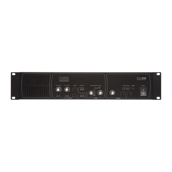
    Front panel – connections and controls VMA 120 MUSIC SOURCE – rotary switch, selects a music source from LINE 1, LINE 2, LINE 3 or the adjacent AUX input [2]. AUX – 3.5 mm jack socket for the temporary connection of laptops, tablets, smartphones, etc. The socket is a TRS type, wired T= left, R = right, S = screen.
  • Page 10 Block Diagram VMA Series Installation Guide V1.0...
  • Page 11 Table of internal jumpers The VMA120 and VMA240 will function as required “out of the box” for the great majority of installations. However, there are various internal PCB jumpers which may be moved by the installer to enable certain additional functions or to modify the manner in which some features operate.
  • Page 12 Technical Specifications Line Inputs Frequency Response 20 Hz to 20 kHz, ±1 dB Gain range 0 dBu to +20 dBu Input impedance 47 kohms Noise <-82 dB (22 kHz bandwidth) Equalisation LF: ±10 dB @ 50 Hz HF: ±10 dB @ 10 kHz Microphone Inputs Frequency Response -3 dB @100 Hz (fixed filter) to 20 kHz, ±1 dB...
  • Page 13 VMA Series Installation Guide V1.0...
  • Page 14 VMA Series Installation Guide V1.0...
  • Page 15 VMA Series Installation Guide V1.0...
  • Page 16 CONTRACTOR SERIES VMA Series Installation Guide V1.0...

This manual is also suitable for:

Vma seriesVma120Vma240

Table of Contents