ACTi I93 Hardware Manual
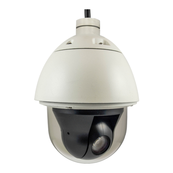
Outdoor ptz/speed dome camera
Hide thumbs
Also See for I93:
- Hardware manual (53 pages) ,
- Installation & configuration note (6 pages) ,
- Hardware manual (48 pages)
Table of Contents
Advertisement
Quick Links
Download this manual
See also:
Hardware Manual
Advertisement
Table of Contents

Related Manuals for ACTi I93


Summary of Contents for ACTi I93
- Page 1 Encoder Firmware V4.06.09 User’s Manual Outdoor PTZ / Speed Dome Camera Hardware Manual I93, I94, I95, I96 2014/01/14...
-
Page 2: Table Of Contents
Other Connections and Accessories ....31 How to Connect Digital Input / Digital Output Devices ......31 How to Use the Power Adaptor .............. 36 How to Attach the Safety Wire Strap ............37 How to Replace the Dome Cover ............39 www.acti.com... - Page 3 Hardware Manual Accessing the Camera ......... 41 Configure the IP Addresses ..............41 Access the Camera .................. 45 www.acti.com...
-
Page 4: Precautions
Every reasonable care has been taken during the writing of this manual. Please inform your local office if you find any inaccuracies or omissions. We cannot be held responsible for any typographical or technical errors and reserve the right to make changes to the product and manuals without prior notice. www.acti.com... - Page 5 This product has been tested and found to comply with the limits for Class B Information Technology Equipment according to European Standard EN 55022 and EN 55024. In a domestic environment, this product may cause radio interference in which cause the user may be required to take adequate measures. www.acti.com...
-
Page 6: Safety Instructions
Safety Check Upon completion of any service or repairs to this video product, ask the service technician to perform safety checks to determine if the video product is in proper operating condition. www.acti.com... -
Page 7: Introduction
1MP Outdoor PTZ with D/N, Extreme WDR, SLLS, 30x Zoom lens 2MP Outdoor PTZ with D/N, Extreme WDR, SLLS, 30x Zoom lens 1MP Outdoor Speed Dome with D/N, Extreme WDR, SLLS, 30x Zoom lens 2MP Outdoor Speed Dome with D/N, Extreme WDR, SLLS, 30x Zoom lens www.acti.com... -
Page 8: Package Contents
Check if the following items come with the camera package. If any of them is missing, please contact your local sales agents or the Customer Help Desk (CHD). Camera Power Cord Power Adaptor Cable Gland Conduit Gland Gland Rubber Rings (x2) Hex Screwdriver Screws Universal Plugs Safety Strap Quick Installation Guide Warranty Card www.acti.com... -
Page 9: Physical Description
The Power LED lights red when the camera is powered up. 3) Ethernet Port The Ethernet port connects to a network using a standard Ethernet cable. 4) AC 24V Power Input This jack connects to the power adaptor and power cord to supply power to the camera. www.acti.com... - Page 10 This jack connects to an audio input device, such as a microphone with built-in amplifier. NOTE: Make sure that the connected audio input device has a built-in amplifier. Connecting an ordinary microphone will dwarf sounds and will result in inaudible recording. www.acti.com...
-
Page 11: Installation
1. Loosen the four (4) screws using the hex screwdriver included in the camera package. 2. Carefully lift the camera cover and place it aside. NOTE: The cover is attached to the camera by a metallic wire strap; do not abruptly lift the cover. www.acti.com... - Page 12 Hardware Manual 3. Remove the styrofoam and silicon bags from the camera. 4. Align the screw holes and tightly secure the screws using the bundled hex screwdriver. www.acti.com...
-
Page 13: Step 2: Mount The Camera
Step 2: Mount the Camera Mounting Options There are several mounting options that you can use to install the camera. For more information about mounting solutions and accessories, please visit our website (http://www.acti.com/mountingselector). Mount Types Accessories Pendant Suitable when mounting the Outdoor PTZ on a hard ceiling. -
Page 14: Other Mounting Accessories
Hardware Manual Mount Types Accessories Corner Suitable when mounting the Outdoor PTZ on a corner wall. Mount PMAX-0305 PMAX-0402 Other Mounting Accessories Accessories PMAX-0700 (Junction Box) PMAX-0104 (Extension Tubes) www.acti.com... -
Page 15: How To Mount The Outdoor Ptz
If the cable connections will be exposed outdoors, make sure to shield or adapt proper waterproofing methods. See Step 3: Waterproof the Cable Connections on page 18. DISCLAIMER: ACTi will not be responsible for camera damage caused by water entering the cable connections. www.acti.com... - Page 16 2. Attach the screws included in the camera package to secure the camera. 3. For added security, attach the safety wire strap to the camera and the mounting solution. How to Attach the Safety Wire Strap on page 37 for detailed instructions. www.acti.com...
- Page 17 Hardware Manual Below is an example of mounting the camera using pendant mount with the cables inside the ceiling. www.acti.com...
-
Page 18: Step 3: Waterproof The Cable Connections
For use with an exterior-grade Ethernet cable in the package). (not included in the package). How to Waterproof the Cable Using How to Waterproof the Cable Using the Conduit Gland on page 23. the Cable Gland on page 19. www.acti.com... -
Page 19: How To Waterproof The Cable Using The Cable Gland
NOTE: Not included NOTE: Not included in the camera in the camera package. package. 2. Detach the cable gland as shown below. Gland Body Clamping Nut Sealing Rubber and Claw 3. Insert the clamping nut through the Ethernet cable. www.acti.com... - Page 20 Make sure the rubber ring is completely aligned on the gap on the gland body. 6. Attach the gland body to the Ethernet port of the camera. IMPORTANT! Make sure the rubber ring is completely aligned and flat on the gland body to avoid possible water leakage. www.acti.com...
- Page 21 8. Insert the sealing rubber and claw into the cable gland body. 9. Attach the clamping nut to the cable gland body. Make sure the clamping nut is tightly secured and the rubber is squeezed in to avoid water leakage. www.acti.com...
- Page 22 It is recommended to place the power adaptor indoors or housed it inside a junction box (see How to Use the Junction on page 27). DISCLAIMER: ACTi will not be responsible for camera damage caused by improper use of the power adaptor. www.acti.com...
-
Page 23: How To Waterproof The Cable Using The Conduit Gland
2. Detach the conduit gland as shown below. Gland Body Clamping Nut Sealing Rubber 3. Insert the Ethernet cable through the flexible conduit. Then insert the clamping nut through the flexible conduit. www.acti.com... - Page 24 Make sure the rubber ring is completely aligned on the gap on the gland body. 6. Attach the gland body to the Ethernet port of the camera. IMPORTANT! Make sure the rubber ring is completely aligned and flat on the gland body to avoid possible water leakage. www.acti.com...
- Page 25 7. Connect the Ethernet connector to the Ethernet port of the camera. 8. Insert the sealing rubber into the conduit gland body. 9. Attach the clamping nut to the conduit gland body. Make sure the clamping nut is tightly secured to avoid water leakage. www.acti.com...
- Page 26 It is recommended to place the power adaptor indoors or housed it inside a junction box (see How to Use the Junction on page 27). DISCLAIMER: ACTi will not be responsible for camera damage caused by improper use of the power adaptor. www.acti.com...
-
Page 27: How To Use The Junction Box
2. From the network/power source side, insert the cables, such as the Ethernet cable, through a flex conduit with 3/4" gland (flex conduit and gland not included in the package) and through one of the holes of the junction box. Then connect the necessary cables. Hole size = 3/4" www.acti.com... - Page 28 Connect the power cord to the power adaptor. c. Connect the power connector of the camera to the cable connector of the adaptor. d. Install a female power socket (not included) inside the junction box to plug the cord and power up the camera. www.acti.com...
- Page 29 Hardware Manual Below is an example of the installing the camera using the Heavy Duty Wall Mount and Junction Box. www.acti.com...
-
Page 30: Step 4: Connect The Equipment
Note: Use only the supplied power adaptor and power cord that came with the camera or the optional High PoE Injector available for purchase. Using other accessories not approved by the manufacturer may cause damage to the equipment. www.acti.com... -
Page 31: Other Connections And Accessories
For example, you can connect an “alarm horn” to the camera; as such when an event occurs inside the camera (e.g. detected intruder), the alarm horn will sound. Other common DO device applications are motion-triggered lights, electric fence, magnetic door locks, etc. www.acti.com... - Page 32 DO1 and 12V Yellow Digital Output 1 (DO1) DO2 and 12V Blue Digital Output 2 (DO2) NOTE: In case of connecting two (2) DO devices, the 12V pin can be commonly shared by the two (2) DO devices. www.acti.com...
- Page 33 Red (12V) and the Yellow (DO1) cables to connect a DO device. See wiring scheme below: Consequently, to connect a second DI or DO device, use the Black (GND) and Green (DI2) cables to connect the second DI device, and the Red (12V) and Blue (DO2) cables for the second DO device. www.acti.com...
- Page 34 Note that when choosing an appropriate relay, please refer to its specifications and make sure they match the above design. The triggering circuit voltage has to be around 12V DC and the switch-controlled circuit voltage has to match the external power supply (e.g. 110V AC or 220V AC). www.acti.com...
- Page 35 110V-220V AC External Power Source Relay (DO1 Device) Outdoor PTZ Illuminator Note: For more information on DI/DO connections, please refer to the article All about Digital Input and Digital Output (http://www.acti.com/kb/detail.asp?KB_ID=KB20091230001) in the Knowledge Base section of our website (www.acti.com). www.acti.com...
-
Page 36: How To Use The Power Adaptor
1. Slide the voltage switch to set the adaptor voltage according to the voltage standard in your location. 2. Connect the power cord to the power adaptor. 3. Connect the power connector of the camera to the cable connector of the adaptor. Power Adaptor Camera Side Side www.acti.com... -
Page 37: How To Attach The Safety Wire Strap
Hardware Manual How to Attach the Safety Wire Strap Most of ACTi’s mounting accessories have a safety screw where the bundled safety wire strap can be used as additional protection to avoid dropping the camera while mounted on the high ceilings, etc. - Page 38 Hardware Manual 4. Align the bigger end of the safety wire strap on the mounting solution and then tightly attach the screw to lock the safety wire strap in place. www.acti.com...
-
Page 39: How To Replace The Dome Cover
1. Loosen the four (4) screws using the hex screwdriver included in the camera package. 2. Carefully lift the cover. Using a screwdriver, remove the screw to detach the cover from the camera. 3. Prepare the replacement dome cover. Below is an example of the smoke vandal proof cover. www.acti.com... - Page 40 Hardware Manual 4. Attach the dome cover to the camera by securing the screw through the wire strap. 5. Tighten the four (4) screws to close the dome cover. www.acti.com...
-
Page 41: Accessing The Camera
In the example below, the camera model that has just been connected to the network is successfully found. Double-click the mouse on the camera model name, the default browser of the PC is automatically launched and the IP address of the target camera is already filled in the address bar of the browser. www.acti.com... - Page 42 The IP Utility can be downloaded for free from http://www.acti.com/IP_Utility When you launch IP Utility, the list of connected cameras in the network will be shown. See sample illustration below: The camera model name is shown on the list.
- Page 43 PC has to be configured to match the network segment of the camera. Manually adjust the IP address of the PC In the following example, based on Windows 7, we will configure the IP address to 192.168.0.99 and set Subnet Mask to 255.255.255.0 by using the steps below: www.acti.com...
- Page 44 In such case, please plug in only one camera at a time, and change its IP address by using the Web browser before plugging in the next one. This way, the Web browser will not be confused about two devices having the same IP address at the same time. www.acti.com...
-
Page 45: Access The Camera
– the user just has to accept the use of such control when prompted so. No other third party utilities are required to be installed in such case. The following examples in this manual are based on Internet Explorer browser in order to cover all functions of the camera. www.acti.com... - Page 46 HTTP port of the camera is 80, which can be omitted from the address for convenience. Before logging in, you need to know the factory default Account and Password of the camera. Account: Admin Password: 123456 For further operations, please refer to the Firmware User’s Manual. www.acti.com...
Need help?
Do you have a question about the I93 and is the answer not in the manual?
Questions and answers