
Subscribe to Our Youtube Channel
Related Manuals for ACTi B913


Summary of Contents for ACTi B913
- Page 1 Indoor PTZ / Speed Dome Camera Hardware Manual B913, B923, B934, I92, I92, I912 Ver. 2018/08/09...
-
Page 2: Table Of Contents
Safety Instructions..................6 Introduction List of Models ....................7 Package Contents ..................8 Physical Description ................. 9 B913, B923, B934 ................9 I91, I92, I912 ................10 Before Installation Unpacking the Camera ................11 Preparing the Power Adapter..............12 Preparing the DI/DO Connector ............14 Installation Procedures Mounting Solutions ................. - Page 3 Hardware Manual How to Replace the Dome Cover ............38 How to Reset the Camera ..............39 Accessing Camera Configure the IP Addresses ..............40 Access the Camera .................. 44 www.acti.com...
-
Page 4: Precautions
Every reasonable care has been taken during the writing of this manual. Please inform your local office if you find any inaccuracies or omissions. ACTi will not be held responsible for any typographical or technical errors and reserves the right to make changes to the product and manuals without prior notice. - Page 5 This product has been tested and found to comply with the limits for Class B Information Technology Equipment according to European Standard EN 55022 and EN 55024. In a domestic environment, this product may cause radio interference in which cause the user may be required to take adequate measures. www.acti.com...
-
Page 6: Safety Instructions
Safety Check Upon completion of any service or repairs to this product, ask the service technician to perform safety checks to determine if the product is in proper operating condition. www.acti.com... -
Page 7: Introduction
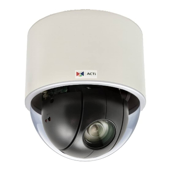
Hardware Manual Introduction List of Models This hardware manual contains the following models: B913 5MP, Indoor Speed Dome, Day / Night, Extreme WDR, Superior Low Light Sensitivity, 30x optical 3MP, Video Analytics Indoor Speed Dome, Day / Night, Extreme B923... -
Page 8: Package Contents
Hardware Manual Package Contents Camera Power Adapter Universal Plug Converter Surface Mount Mounting Screw Kit Fixing Bracket Terminal Block Terminal Block Drill Template (for Power) (for DIO/DO) Drill Template Quick Installation Guide Warranty Card Warranty Card www.acti.com... -
Page 9: Physical Description
Hardware Manual Physical Description B913, B923, B934 Connectors View Internal View Item Description Digital Input / Output Connects to digital input or output devices, such as an alarm (DI/DO) trigger, panic button, etc. Digital Input (DI) and Digital Output (DO) devices are used in applications like motion detection, event triggering, alarm notifications, etc. -
Page 10: I91, I92, I912
Press and hold the Reset button for 5 seconds or until the Power LED goes off. See How to Reset the Camera on page 39. Power LED The Power LED lights red when the camera is powered up. www.acti.com... -
Page 11: Before Installation
However, the plastic has been removed on the pictures in this documentation to show clarity of the procedures being described. 1. Rotate the dome cover counter-clockwise to remove it. 2. Remove the Styrofoam. www.acti.com... -
Page 12: Preparing The Power Adapter
The power adapter must be connected to the supplied terminal block before use. To do this, follow the procedures below: 1. Loosen the screws of the 12V and GND pins of the power terminal block. www.acti.com... - Page 13 3. Connect the wire with the white stripe to the 12V pin and the other to the GND pin. 4. Tighten the screws of the 12V pin and the GND pins to secure the wire connection. 5. Attach one of the bundled adapter plugs suitable in your location. www.acti.com...
-
Page 14: Preparing The Di/Do Connector
To connect output devices (DO), map the pins to one of the pin combinations below: Device Mapping Instructions Connect the wires of the first output device to 12V Digital Output 1 (DO1) and DO1. Connect the wires of the second output device to 12V Digital Output 2 (DO2) and DO2. www.acti.com... - Page 15 DO device. See wiring scheme below: Consequently, to connect a second DI or DO device, use the GND and DI2 pins to connect a second DI device, and the 12V and DO2 to connect a second DO device. www.acti.com...
- Page 16 The illustration below is a graphic example of connecting a relay to a high voltage DO device. 110V-220V AC External Power Source Relay (DO1 Device) Camera Illuminator NOTE: For more information on DI/DO connections, please refer to the Knowledge Base article All About Digital Input and Digital Output downloadable from the link below (http://Download.acti.com?id=516). www.acti.com...
-
Page 17: Installation Procedures
23 for mounting instructions. PMAX-1010 Pendant Mount Suitable when mounting the camera on hard and high ceilings. PMAX-0110 PMAX-0103 (Straight Tube with Bracket) PMAX-0110 PMAX-0102 (Straight Tube) Straight Wall Suitable when mounting the camera on straight walls. Mount PMAX-0311 (L-Type Wall Mount) www.acti.com... - Page 18 Suitable when mounting the camera on vertical poles. Mount PMAX-0110 PMAX-0303 PMAX-0503 Horizontal Pole Suitable when mounting the camera on horizontal poles. Mount PMAX-0110 PMAX-0102 PMAX-0503 Corner Mount Suitable when mounting the camera on a corner wall. PMAX-0110 PMAX-0303 PMAX-0402 www.acti.com...
-
Page 19: Other Mounting Accessories
For more information about the mounting solutions and accessories, please check the Mounting Accessory Selector in our website (http://www.acti.com/mountingselector). Except for the Surface Mount, the above mounting accessories are not included in the package. Contact your sales agents to purchase. -
Page 20: Mounting On The Ceiling
1. Using the mount drill template, mark the screw holes on the ceiling, then drill the holes and insert the supplied plastic plugs. 2. Push at the marked points below to detach the cover ring from the metal plate. 3. Attach the metal plate to the ceiling using the three (3) supplied screws. www.acti.com... - Page 21 (holes marked below). The fixing bracket will fix the camera position when mounted later. 5. Align and insert the camera base hooks to the mounting holes of the metal plate. 6. Slide the camera clockwise to secure the hooks to the mount. www.acti.com...
- Page 22 10. Note that the cables will pass through the cut, align the metal plate hooks onto the holes of the cover ring and then push to secure it in place. Final installation would look similar to the picture below. www.acti.com...
-
Page 23: Using The Flush Mount
Step 1: Drill a Hole on the Ceiling Drill a 184-mm diameter hole on the ceiling where you want to mount the camera, then route the network cable, power adapter, and other cables (e.g. DI/DO, audio cables, etc.) through the hole. www.acti.com... - Page 24 Peel off the lining of the three (3) foam rubber pads and attach a rubber pad to each retaining bracket. Step 3: Loosen the Retaining Brackets Using a screwdriver, loosen the retaining brackets according to the thickness of the ceiling. www.acti.com...
- Page 25 2. Position the retaining brackets to hold the mount on the ceiling. NOTE: The following illustration shows how the flush mount will look like when viewed from inside the ceiling. In case you cannot access inside the ceiling, use your fingers to position the retaining brackets through the hole. www.acti.com...
- Page 26 (if necessary) are routed on the outer gap of the metal bracket. 4. Attach the fixing bracket to one of the holes on the camera using the supplied screw (holes marked below). The fixing bracket will fix the camera position when mounted later. www.acti.com...
- Page 27 The bundled network extension cable is flexible enough to be bent and makes it easy to insert the camera through the mount. Or, if you can access the inside of the ceiling, you may mount the camera first and then connect the cables. www.acti.com...
- Page 28 3. Tighten the screw on the fixing bracket to fix the camera position. This is to avoid accidental camera movement as the camera performs PTZ functions. Step 7: Attach the Cover Ring 1. Align the metal latches and the latches on the cover ring. 2. Push to firmly secure the cover ring latches. www.acti.com...
-
Page 29: Using The Pendant Mount
Note that you must insert the power adapter cable first to fit the tube. NOTE: If using a straight tube without bracket, route the cables to pass through the hole on the ceiling. The following illustrations show the installation using a straight tube with bracket. www.acti.com... - Page 30 1. Insert the cables from the tube into the mount kit and route them to pass through the outer bracket. 2. Align the slot of the mount kit to the tab inside the straight tube and install the mount kit. www.acti.com...
- Page 31 If the network cable texture is rough and not easily bent, use the bundled network extension cable (included in the mount kit package) to easily route the cables because of its flexibility. 2. Align and insert the camera base hooks to the mounting holes. www.acti.com...
- Page 32 3. Slide the camera counter-clockwise to secure the hooks to the mount. 4. On the top of the mount kit, attach three (3) screws (included in the mount kit package) to secure the camera to the mount. The final installation would look similar to the one below: www.acti.com...
-
Page 33: Mounting On Straight Wall
Use the drill template (included in the L-type wall mount package) to mark and drill the mounting holes on the wall. Route the cable(s). 2a. If the cable(s) will pass through the wall, insert the cable(s) through the cable hole as marked below (A). www.acti.com... - Page 34 L-type wall mount onto the wall. Step 2: Install the Camera 1. Connect the network cable to the Ethernet port of the camera. If necessary, connect the other cables (such as power adapter, DI/DO, etc.) to the corresponding connectors. www.acti.com...
- Page 35 2. Align and insert the camera base hooks to the mounting holes. 3. Slide the camera clockwise to secure the hooks to the mount. 4. Attach three (3) screws (included in the L-type wall mount package) to secure the camera to the mount. www.acti.com...
-
Page 36: Other Accessories And Adjustments
Other Accessories and Adjustments How to Install / Remove the Memory Card NOTE: Supports microSDHC and microSDXC cards. B913, B923, B934 1. Rotate the dome cover counter-clockwise to remove it. 2. Insert the memory card into the card slot near the camera shot. -
Page 37: I91, I92, I912
In case there is a need to remove the card, make sure to access the camera Web Configurator to safely “unmount” the card first (see the camera Firmware User’s Manual for more information). Once unmounted from the firmware, push the card to eject it from the slot. www.acti.com... -
Page 38: How To Replace The Dome Cover
Depending on your surveillance needs, you may want to replace the bundled dome cover with a smoke dome cover available for purchase. To replace the dome cover, do the following: 1. Rotate the dome cover counter-clockwise to remove it. 2. Rotate the replacement dome cover clockwise to attach it. www.acti.com... -
Page 39: How To Reset The Camera
In case of connectivity issues or abnormal video quality. With the camera powered on, use a pointed object, such as a pen, to press and hold the reset button for at least 5 seconds or until the Power LED goes off. www.acti.com... -
Page 40: Accessing Camera
Windows system – just by pressing the “Network” icon, all the cameras of the local area network will be discovered by Windows, thanks to the UPnP function support of our cameras. In the example below, the camera that has just been connected to the network is successfully found. www.acti.com... - Page 41 Download IP Utility for free from http://www.acti.com/product/IP%20Utility%204. When you launch IP Utility, the list of connected cameras in the network will be shown. See sample illustration below: You can quickly notice the camera model in the list.
- Page 42 PC has to be configured to match the network segment of the camera. Manually adjust the IP address of the PC In the following example, based on Windows 7, we will configure the IP address to 192.168.0.99 and set Subnet Mask to 255.255.255.0 by using the steps below: www.acti.com...
- Page 43 In such case, please plug in only one camera at a time, and change its IP address by using the Web browser before plugging in the next one. This way, the Web browser will not be confused about two devices having the same IP address at the same time. www.acti.com...
-
Page 44: Access The Camera
Upon successful connection to the camera, the user interface called Web Configurator would appear together with the login page. The HTTP port number was not added behind the IP address since the default HTTP port of the camera is 80, which can be omitted from the address for convenience. www.acti.com... - Page 45 Hardware Manual Before logging in, you need to know the factory default Account and Password of the camera. Account: Admin Password: 123456 For further operations, please refer to the Firmware User’s Manual. www.acti.com...
- Page 46 Copyright © 2018, ACTi Corporation All Rights Reserved 7F, No. 1, Alley 20, Lane 407, Sec. 2, Ti-Ding Blvd., Neihu District, Taipei, Taiwan 114, R.O.C. TEL : +886-2-2656-2588 FAX : +886-2-2656-2599 Email: sales@acti.com...
Need help?
Do you have a question about the B913 and is the answer not in the manual?
Questions and answers