Table of Contents
Advertisement
Quick Links
Download this manual
See also:
Installation Manual
Advertisement
Table of Contents

Related Manuals for ACTi B412


Summary of Contents for ACTi B412
- Page 1 Zoom Bullet Series Hardware Manual B412, B415, B416 I42, I48 2017/09/29...
-
Page 2: Table Of Contents
Connecting Digital Input / Output Devices (Optional) ......31 Connecting Audio Input / Output Devices (Optional) ......34 Other Adjustments and Accessories ....35 How to Install / Remove a Memory Card (Optional) ......35 How to Insert the Memory Card on B412 ..........35 www.acti.com... - Page 3 How to Position Camera for Corridor View Format ......37 How to Attach the Sunshield ..............39 How to Reset the Camera ............... 40 Accessing the Camera ......... 41 Configure the IP Addresses ..............41 Access the Camera .................. 45 www.acti.com...
-
Page 4: Precautions
Every reasonable care has been taken during the writing of this manual. Please inform your local office if you find any inaccuracies or omissions. ACTi will not be held responsible for any typographical or technical errors and reserves the right to make changes to the product and manuals without prior notice. - Page 5 This product has been tested and found to comply with the limits for Class B Information Technology Equipment according to European Standard EN 55022 and EN 55024. In a domestic environment, this product may cause radio interference in which cause the user may be required to take adequate measures. www.acti.com...
-
Page 6: Safety Instructions
Safety Check Upon completion of any service or repairs to this product, ask the service technician to perform safety checks to determine if the product is in proper operating condition. www.acti.com... -
Page 7: Introduction
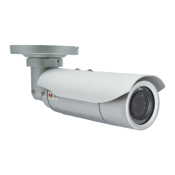
Introduction The List of Models This hardware manual contains the following models: 3MP Video Analytics Zoom Bullet with D/N, Adaptive IR, Extreme WDR, B412 SLLS, 10x Zoom lens 2MP Video Analytics Zoom Bullet with D/N, Adaptive IR, Extreme WDR, B415... -
Page 8: Package Contents
Hardware Manual Package Contents Camera Bracket Plate Sunshield Hexagon Screwdriver Mounting Screw Kit Sunshield Screws Female Conduit Gland Female Cable Gland Gland Rubber Ring x2 Terminal Block Terminal Block Drill Template Sticker (for Power) (for DI/DO) Drill Template www.acti.com... - Page 9 Hardware Manual Quick Installation Guide Warranty Card Warranty Card NOTE: The pictures are for reference only. Actual items may slightly vary. www.acti.com...
-
Page 10: Physical Description
Hardware Manual Physical Description B412 Item Description Ethernet Port Connects to a network using a standard Ethernet cable. Audio Input Connects to a microphone with built-in amplifier. See (Red) Connecting Audio Input / Output Devices (Optional) on page 34 for more information. - Page 11 Use to release moisture trapped inside the camera chassis. Built-in Use to monitor or record voices along with the video. Microphone Select whether to use the built-in or the line-in microphone as source of audio from the camera web configurator. See the camera Firmware Manual details. www.acti.com...
-
Page 12: B415, B416, I42, I48
(Green) etc. See Connecting Audio Input / Output Devices (Optional) on page 34 for more information. NOTE: If the audio connectors will not be used, leave the rubber caps on to ensure cables remain waterproof and eliminate short-circuit hazards. www.acti.com... - Page 13 NOTE: For typical use, the power LED is hidden inside the housing and cannot be seen. However, knowing how the Power LED works is essential when troubleshooting or doing a reset. www.acti.com...
-
Page 14: Mounting Options
PMAX-0504 or PMAX-0505 NOTE: For more information about the mounting solutions and accessories, please check the Mounting Accessory Selector in our website (http://www.acti.com/mountingselector). The above mounting accessories are not included in the package. Contact your sales agents to purchase. www.acti.com... -
Page 15: Installation Procedures
2. Determine if the camera will be used in normal or corridor format. See How to Position Camera for Corridor View Format on page 37. 3. Attach the sunshield. See How to Attach the Sunshield on page 39. Step 2: Attach the Camera Bracket 1. Attach the bracket to the camera. www.acti.com... -
Page 16: Step 3: Mount The Camera
3. Detach the drill template sticker and insert the plastic plugs into the screw holes. 4. If the cables will pass through a hole on the surface, route the cables through the hole on the wall. If the cables will go along the wall, route the cables through the gap on the bracket. www.acti.com... -
Page 17: Step 4: Pan And Tilt The Camera
5. Attach the camera to the surface using the three (3) supplied screws. Step 4: Pan and Tilt the Camera Pan Adjustment Screw Pan Adjustment Knob Tilt Adjustment Screw 1. Slightly loosen the Pan Adjustment Knob and pan the camera. www.acti.com... - Page 18 2. When panning is done, tighten the knob. Tighten the set screw on the knob to fix the pan position. 3. Loosen the Tilt Adjustment Screw to adjust the camera tilt angle. When done, tighten the Tilt Adjustment Screw to fix the tilt position. www.acti.com...
-
Page 19: Step 5: Waterproof The Cable Connections
For use with an exterior-grade Ethernet cable included in the package). (not included in the package). How to Waterproof the Cable Using How to Waterproof the Ethernet Cable Using the Cable Gland on page 20. the Conduit Gland on page 24. www.acti.com... -
Page 20: How To Waterproof The Ethernet Cable Using The Cable Gland
Cable Gland Gland Rubber Ring Ethernet Cable NOTE: Not included in the camera package. 2. Detach the cable gland as shown below. Gland Body Clamping Nut Sealing Rubber and Claw 3. Insert the clamping nut through the Ethernet cable. www.acti.com... - Page 21 Make sure the rubber ring is completely aligned on the gap on the gland body. 6. Attach the gland body to the Ethernet port of the camera. IMPORTANT! Make sure the rubber ring is completely aligned and flat on the gland body to avoid possible water leakage. www.acti.com...
- Page 22 8. Insert the sealing rubber and claw into the cable gland body. 9. Attach the clamping nut to the cable gland body. Make sure the clamping nut is tightly secured and the rubber is squeezed in to avoid water leakage. www.acti.com...
- Page 23 Connecting Audio Input / Output Devices (Optional) on page 34. NOTE: Different applications and installation environments require different types of waterproofing methods which may not be covered in this manual. Check your installation environment and adapt a suitable waterproofing method. www.acti.com...
-
Page 24: How To Waterproof The Cable Using The Conduit Gland
NOTE: Not included in the camera package. 2. Detach the conduit gland as shown below. Gland Body Clamping Nut Sealing Rubber 3. Insert the Ethernet cable through the flexible conduit. Then insert the clamping nut through the flexible conduit. www.acti.com... - Page 25 Make sure the rubber ring is completely aligned on the gap on the gland body. 6. Attach the gland body to the Ethernet port of the camera. IMPORTANT! Make sure the rubber ring is completely aligned and flat on the gland body to avoid possible water leakage. www.acti.com...
- Page 26 To connect digital input or output device, see Connecting Digital Input / Output Devices (Optional) on page 31. c. To connect audio input or output device, see Connecting Audio Input / Output Devices (Optional) on page 34. www.acti.com...
-
Page 27: Step 6: Connect To Network
In case of using a non-PoE switch, power up the camera using a power adapter (not supplied). As needed, power up the other connected devices. Step 7: Access Camera Live View Accessing the Camera on page 41 for more information on how to access the camera live view. www.acti.com... -
Page 28: Other Connections
The power adapter must be connected to the supplied terminal block before use. To do this, follow the procedures below: 1. Loosen the screws of the 12V and GND pins of the power terminal block. www.acti.com... - Page 29 3. Connect the wire with the white stripe to the 12V pin and the other to the GND pin. NOTE: The terminal block pictures are for reference only, note that actual label placement may vary per model. 4. Tighten the screws of the 12V pin and the GND pins to secure the wire connection. www.acti.com...
- Page 30 Hardware Manual 5. Below is an example of a power adapter with an attached terminal block. Connect the terminal block connector to the connector on the camera. NOTE: The power adapter is not bundled in the package. www.acti.com...
-
Page 31: Connecting Digital Input / Output Devices (Optional)
Connect the terminal block to the cable connector of the camera. After mapping the wires, connect the terminal block to the connector on the camera and make sure to wrap the cable connection using a waterproof tape. www.acti.com... - Page 32 DI/DO device to an external power source. In this case, use the GND and DI pins to connect a DI device and use the 12V and DO pins to connect a DO device. See wiring scheme below: www.acti.com...
- Page 33 The illustration below is a graphic example of connecting a relay to a high voltage DO device. 110V-220V AC External Power Source Relay (DO1 Device) Camera Illuminator NOTE: For more information on DI/DO connections, please refer to the Knowledge Base article All About Digital Input and Digital Output downloadable from the link below (http://Download.acti.com?id=516). www.acti.com...
-
Page 34: Connecting Audio Input / Output Devices (Optional)
Enable Audio In and select Line in as the Microphone Type in the camera firmware to receive audio. After connecting a device, make sure to wrap the cable connection using a waterproof tape. www.acti.com... -
Page 35: Other Adjustments And Accessories
Supports microSDHC and microSDXC cards. How to Insert the Memory Card on B412 The memory card slot on B412 is located inside the front cover. 1. Loosen the four (4) screws to open the front cover of the camera. 2. Insert a memory card into the slot with the metallic contacts facing down. Push the card until it clicks into place. -
Page 36: How To Remove The Memory Card
In case there is a need to remove the card, make sure to access the camera Web Configurator to safely “unmount” the card first (see the camera Firmware manual for more information). Once unmounted from the firmware, push the card to eject it from the slot. www.acti.com... -
Page 37: How To Position Camera For Corridor View Format
3. Attach the sunshield to its position based on the camera orientation. Since the default sunshield position is for the camera normal view format, you must move the set screw position first. 4. Remove the two (2) set screws from its original position. www.acti.com... - Page 38 7. Cover the unused screw holes with the two (2) rubber plugs. 8. Follow the instructions on How to Attach the Sunshield on page 39. Note that the instructional pictures may show a different camera orientation; the procedures are the same, though. www.acti.com...
-
Page 39: How To Attach The Sunshield
1. Loosely secure the supplied screws to attach the sunshield. 2. Slide to adjust the sunshield to cover the lens as far as possible. NOTE: The sunshield may have to be adjusted later based on the camera live view. 3. Tighten the screws to secure the sunshield. www.acti.com... -
Page 40: How To Reset The Camera
In case of IP address, mask, or allow/deny filter related issues, resulting with inability to modify these settings. In case of connectivity issues or abnormal video quality. To reset the camera, do the following: 1. Remove the Reset Button cover. 2. Press and hold the Reset button for at least 5 seconds. www.acti.com... -
Page 41: Accessing The Camera
Windows system – just by pressing the “Network” icon, all the cameras of the local area network will be discovered by Windows thanks to the UPnP function support of our cameras. In the example below, we successfully found the camera model that had just connected to the network. www.acti.com... - Page 42 Search and downloand IP Utility for free from http://www.acti.com/DownloadCenter. With just one click, you can launch the IP Utility and there will be an instant report as follows: You can quickly notice the camera model in the list.
- Page 43 PC has to be configured to match the network segment of the camera. Manually adjust the IP address of the PC: In the following example, based on Windows 7, we will configure the IP address to 192.168.0.99 and set Subnet Mask to 255.255.255.0 by using the steps below: www.acti.com...
- Page 44 In such case, please plug in only one camera at a time, and change its IP address by using the Web browser before plugging in the next one. This way, the Web browser will not be confused about two devices having the same IP address at the same time. www.acti.com...
-
Page 45: Access The Camera
Upon successful connection to the camera, the user interface called Web Configurator would appear together with the login page. The HTTP port number was not added behind the IP address since the default HTTP port of the camera is 80, which can be omitted from the address for convenience. www.acti.com... - Page 46 Hardware Manual Before logging in, you need to know the factory default Account and Password of the camera. Account: Admin Password: 123456 For further operations, please refer to the Firmware User Manual. www.acti.com...
- Page 47 Copyright © 2016, ACTi Corporation All Rights Reserved 7F, No. 1, Alley 20, Lane 407, Sec. 2, Ti-Ding Blvd., Neihu District, Taipei, Taiwan 114, R.O.C. TEL : +886-2-2656-2588 FAX : +886-2-2656-2599 Email: sales@acti.com...
Need help?
Do you have a question about the B412 and is the answer not in the manual?
Questions and answers