
Related Manuals for ACTi B41


Summary of Contents for ACTi B41
- Page 1 Zoom Bullet Series Hardware Manual B41, B44, B45, B46, B47, B49, B410 I44, I45, I47 2015/05/18...
-
Page 2: Table Of Contents
How to Use the Female Conduit Gland ..........22 Waterproof Solution Using the Camera Connectors ............26 How to Use the Male Cable Gland (Optional) ........28 How to Use the Male Conduit Gland ............32 Other Connections..........36 Connecting a Power Adapter (Optional) ..........36 www.acti.com... - Page 3 How to Insert a Memory Card ..............45 How to Insert the Memory Card ............45 How to Remove the Memory Card ............45 Accessing the Camera ......... 46 Configure the IP Addresses ..............46 Access the Camera .................. 50 www.acti.com...
-
Page 4: Precautions
Every reasonable care has been taken during the writing of this manual. Please inform your local office if you find any inaccuracies or omissions. ACTi will not be held responsible for any typographical or technical errors and reserves the right to make changes to the product and manuals without prior notice. - Page 5 This product has been tested and found to comply with the limits for Class B Information Technology Equipment according to European Standard EN 55022 and EN 55024. In a domestic environment, this product may cause radio interference in which cause the user may be required to take adequate measures. www.acti.com...
-
Page 6: Safety Instructions
Safety Check Upon completion of any service or repairs to this product, ask the service technician to perform safety checks to determine if the product is in proper operating condition. www.acti.com... -
Page 7: Introduction
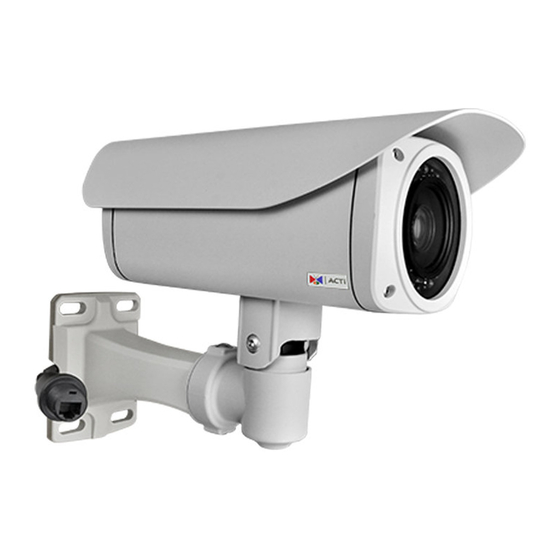
2MP Zoom Bullet with D/N, Adaptive IR, Extreme WDR, ELLS, 30x Zoom lens 4MP Zoom Bullet with D/N, Adaptive IR, Advanced WDR, SLLS, 30x Zoom lens From the installation perspective these models are very similar; therefore you can use one manual for all of them. www.acti.com... -
Page 8: Package Contents
Hardware Manual Package Contents Camera Sunshield Sunshield Screws Hexagon Screwdriver Camera Base Wrench Bracket Wrench Female Conduit Gland Female Cable Gland Washer Male Cable Gland Male Conduit Gland Drill Template Sticker (Optional) Drill Template www.acti.com... - Page 9 Hardware Manual Terminal Block Terminal Block Quick Installation Guide (for Power) (for Audio and DI/DO) Warranty Card NOTE: The pictures are for reference only. Actual items may slightly vary. www.acti.com...
-
Page 10: Physical Description
2) Memory Card Slot Insert a memory card into this slot for local recording purposes. See How to Insert a Memory Card on page 45for more information. NOTE: Supports microSDHC and microSDXC cards. www.acti.com... - Page 11 The Power LED lights red when the camera is powered on and goes off once the camera boot-up process is complete. NOTE: For typical use, the power LED is hidden inside the housing and cannot be seen. However, knowing how the power LED works is essential when troubleshooting or doing a reset. www.acti.com...
-
Page 12: Mounting Options
PMAX-0504 NOTE: For more information about the mounting solutions and accessories, please check the Mounting Accessory Selector in our website (http://www.acti.com/mountingselector). The above mounting accessories are not included in the package. Contact your sales agents to purchase. www.acti.com... -
Page 13: Installation Procedures
Cable hole If the cable will be routed along the wall, just drill the four (4) screw holes on the wall. 4. Detach the drill template sticker from the wall and insert the plastic plugs into the screw holes. www.acti.com... -
Page 14: Step 2: Attach The Sunshield
1. Loosely secure the supplied screws to attach the sunshield. 2. Slide to adjust the sunshield to cover the lens as far as possible. NOTE: The sunshield may have to be adjusted later based on the camera live view. 3. Tighten the screws to secure the sunshield. www.acti.com... -
Page 15: Step 3: Install The Camera
2. Install the camera to the wall using four (4) screws applicable for the wall material (purchased separately). NOTE: Make sure the wall can bear more than the weight of the camera with bracket. Step 4: Waterproof and Connect the Network Cable Waterproof Solution Using the “Pigtail” on page 18. www.acti.com... -
Page 16: Step 5: Connect To Network
In case of using a non-PoE switch, power up the camera using a power adapter (not supplied). As needed, power up the other connected devices. Step 6: Access Camera Live View Accessing the Camera on page 46 for more information on how to access the camera live view. www.acti.com... -
Page 17: Step 7: Adjust The Viewing Angle
1. Loosen the tilt adjustment screws, adjust the camera tilt, and then tighten back the screws to fix the tilt position. 2. Loosen the pan adjustment screw, move the pan direction, and then tighten back the screw to fix the pan position. www.acti.com... -
Page 18: Waterproof Solution Using The "Pigtail
See Waterproof Solution Using the Camera Connectors on page 26 for cabling information. www.acti.com... -
Page 19: How To Use The Female Cable Gland
Not included in the package. Washer (included in the camera package) Perform the following to waterproof the “pigtail” using the female cable gland: 1. Disassemble the female cable gland as shown below: Clamping Sealing Cable Gland Insert www.acti.com... - Page 20 Hardware Manual 2. Insert the clamping nut into the Ethernet cable. 3. Insert the sealing insert with claw. 4. Insert the gland body into the Ethernet cable. 5. On the “pigtail” side, insert the washer into the “pigtail”. www.acti.com...
- Page 21 8. Insert the sealing insert into the cable gland body and then attach the clamping nut to complete the cable solution. NOTE: Make sure the clamping nut is tightly attached to the cable gland body and the sealing insert is squeezed tightly. www.acti.com...
-
Page 22: How To Use The Female Conduit Gland
CAT 5 or CAT 6 (included in the camera package) (not included in the package) Perform the following to waterproof the “pigtail” using the female conduit gland: 1. Disassemble the female conduit gland as shown below: Sealing Clamping Cable Gland www.acti.com... - Page 23 2. Pull the Ethernet cable through the flex conduit. Leave enough length of the cable outside the flex conduit. 3. Insert the clamping nut into through the flex conduit. 4. Insert the sealing nut and fix it at the end of the flex conduit. 5. Insert the gland body into the Ethernet cable. www.acti.com...
- Page 24 6. On the “pigtail” side, insert the washer into the “pigtail”. 7. Connect the Ethernet cable connector to the “pigtail” connector. 8. Attach the gland body to the “pigtail”. Make sure the gland body is tightly attached to the “pigtail” and the washer is secured NOTE: between them. www.acti.com...
- Page 25 9. Push the flex conduit and insert the sealing nut into the gland body. NOTE: Make sure the clamping nut is tightly attached to the cable gland body and the sealing insert is squeezed tightly. 10. Attach the clamping nut to complete the cable solution. www.acti.com...
-
Page 26: Waterproof Solution Using The Camera Connectors
(when PoE is not available). A flexible conduit (trade size 1/2”) is required to house all the cables. See How to Use the Male Conduit Gland on page 32. NOTE: The flex conduit is not included in the package and must be purchased separately. www.acti.com... - Page 27 “pigtail” from the camera (see How to Remove the “Pigtail” on page 42 for detailed information). 2. Using a coin or screwdriver, remove the cap from the back cover. Then set the back cover aside for later use. www.acti.com...
-
Page 28: How To Use The Male Cable Gland (Optional)
(not included in the package) NOTE: Exterior-grade cables are already waterproof. Not included in the package. Perform the following to use the male cable gland solution: 1. Disassemble the male cable gland as shown below: Sealing Insert Body Clamping with Claw (with Washer) www.acti.com... - Page 29 Hardware Manual 2. Insert the clamping nut into the Ethernet cable. 3. Insert the sealing insert with claw. 4. Attach the gland body to the hole of the cover. www.acti.com...
- Page 30 5. Insert the Ethernet cable through the cable gland, and connect it to the Ethernet port of the camera. 6. Tighten the four (4) screws to secure the camera cover using the hex screwdriver. NOTE: Make sure the cover rubber (black) is intact and properly aligned to the cover. www.acti.com...
- Page 31 7. Insert the sealing insert with claw into the gland body. 8. Attach the clamping nut to complete the cable solution. NOTE: Make sure the clamping nut is tightly attached to the cable gland body and the sealing insert is squeezed tightly. www.acti.com...
-
Page 32: How To Use The Male Conduit Gland
1. Disassemble the male conduit gland as shown below: Lock Nut Sealing Insert Body Clamping Nut NOTE: In this installation, the conduit gland body can be securely attached to the mount kit; therefore the use of lock nut is not necessary. Please set the lock nut aside. www.acti.com... - Page 33 3. Pull enough length of the device cables without connectors through the flex conduit. The terminal blocks will be attached once the cable passes through the gland body and cover later. 4. Insert the clamping nut through the flex conduit. www.acti.com...
- Page 34 5. Insert the sealing insert and attach it at the end of the flex conduit. 6. Pull the device cables through the gland body. 7. Attach the terminal blocks, see Other Connections on page 36 for more information. 8. Connect the cables to the corresponding connectors on the camera. www.acti.com...
- Page 35 10. Insert the sealing insert with claw into the gland body and then attach the clamping nut to complete the cable solution. NOTE: Make sure the clamping nut is tightly attached to the cable gland body and the sealing insert is squeezed tightly. www.acti.com...
-
Page 36: Other Connections
1. Loosen the screws of the 12V and GND pins of the power terminal block. 2. Take note that a standard power adapter cable has two (2) different wires: Connects to GND Pin White stripe: Connects to 12V Pin www.acti.com... - Page 37 4. Tighten the screws of the 12V pin and the GND pins to secure the wire connection. 5. Set the prepared power adapter for connection later. Below is an example of a power adapter with an attached terminal block. NOTE: The power adapter is not bundled in the package. www.acti.com...
-
Page 38: Connecting Di/Do And Audio Devices (Optional)
Mapping Instructions DIO PW or Connect the wires of the output device to DIO PW or 12V and DO. Digital Output (DO) Connect the wires of the input device to DIO GND DIO GND Digital Input (DI) and DI. www.acti.com... - Page 39 DI/DO device to an external power source. In this case, use the DIO GND and DI pins to connect a DI device and use the DIO PW or 12V and DO pins to connect a DO device. See wiring scheme below: www.acti.com...
- Page 40 The illustration below is a graphic example of connecting a relay to a high voltage DO device. 110V-220V AC External Power Source Relay (DO1 Device) Camera Illuminator NOTE: For more information on DI/DO connections, please refer to the Knowledge Base article All About Digital Input and Digital Output downloadable from the link below (http://Download.acti.com?id=516). www.acti.com...
-
Page 41: How To Connect Audio Devices
Audio Input (A1) AI_GND and A_IN or AI. A_IN or AI NOTE: For more information about AUDIO in connections, please refer to the Knowledge Base article How to Use Audio-in of ACTi Cameras, downloadable from the link below (http://Download.acti.com?id=534). www.acti.com... -
Page 42: Other Adjustments And Accessories
“pigtail” from the camera. Follow the procedures below: 1. Loosen the four (4) screws to remove the back cover of the camera. 2. Disconnect the network cable from the Ethernet port and let it loose. This network cable is the other end of the “pigtail”. NOTE: www.acti.com... - Page 43 3. Using the bundled camera base wrench, detach the two (2) screws to remove the bracket. 4. Remove the clamping nut and sealing insert. 5. Remove the rubber from the dome cover. 6. Remove the gland body from the camera. www.acti.com...
- Page 44 8. Using a coin or screwdriver, remove the cap from the back cover. Then attach the cap to close the cable hole. 9. Attach the bracket to the camera. 10. Attach the back cover of the camera (as needed). www.acti.com...
-
Page 45: How To Insert A Memory Card
In case there is a need to remove the card, make sure to access the camera Web Configurator to safely “unmount” the card first (see the camera Firmware manual for more information). Once unmounted from the firmware, push the card to eject it from the slot. www.acti.com... -
Page 46: Accessing The Camera
Windows system – just by pressing the “Network” icon, all the cameras of the local area network will be discovered by Windows thanks to the UPnP function support of our cameras. In the example below, we successfully found the camera model that had just connected to the network. www.acti.com... - Page 47 Search and downloand IP Utility for free from http://www.acti.com/DownloadCenter. With just one click, you can launch the IP Utility and there will be an instant report as follows: You can quickly notice the camera model in the list.
- Page 48 PC has to be configured to match the network segment of the camera. Manually adjust the IP address of the PC: In the following example, based on Windows 7, we will configure the IP address to 192.168.0.99 and set Subnet Mask to 255.255.255.0 by using the steps below: www.acti.com...
- Page 49 In such case, please plug in only one camera at a time, and change its IP address by using the Web browser before plugging in the next one. This way, the Web browser will not be confused about two devices having the same IP address at the same time. www.acti.com...
-
Page 50: Access The Camera
– the user just has to accept the use of such control when prompted so. No other third party utilities are required to be installed in such case. The examples in this manual are based on Internet Explorer browser in order to cover all functions of the camera. www.acti.com... - Page 51 HTTP port of the camera is 80, which can be omitted from the address for convenience. Before logging in, you need to know the factory default Account and Password of the camera. Account: Admin Password: 123456 For further operations, please refer to the Firmware User Manual. www.acti.com...
- Page 52 Copyright © 2015, ACTi Corporation All Rights Reserved 7F, No. 1, Alley 20, Lane 407, Sec. 2, Ti-Ding Blvd., Neihu District, Taipei, Taiwan 114, R.O.C. TEL : +886-2-2656-2588 FAX : +886-2-2656-2599 Email: sales@acti.com...
Need help?
Do you have a question about the B41 and is the answer not in the manual?
Questions and answers