Powermatic 60B Instruction Manual & Parts List
8" jointer
Hide thumbs
Also See for 60B:
- Operating instructions and parts manual (40 pages) ,
- Instruction manual & parts list (12 pages)

Related Manuals for Powermatic 60B


Summary of Contents for Powermatic 60B
- Page 1 8" JOINTER Model 60B Instruction Manual & Parts List M-0460282 (800) 274-6848 www.powermatic.com...
-
Page 2: More Information
This manual has been prepared for the owner and operators of a Powermatic Model 60B, 8" Jointer. Its purpose, aside from proper machine operation, is to promote safety through the use of accepted correct operating and maintenance procedures. Completely read the safety and maintenance instructions before operating or servicing the machine. -
Page 3: Table Of Contents
TABLE OF CONTENTS Safety Rules............................4-5 Safety Decals ............................6 Specifications ............................7 Features ..............................8 Receiving ..............................9 Installation & Assembly..........................9 Aligning Pulleys..........................10 Mounting Drive Belt......................... 10 Mouting Pulley Guard........................11 Mounting Dust Adaptor ........................11 Electrical Connections........................11 Extension Cords .......................... -
Page 4: Safety Rules
Make certain the work area is well lighted and that a proper exhaust system is used to minimize dust. Powermatic recommends the use of anti-skid floor strips on the floor area where the operator normally stands and that each machine's work area be marked off. Provide adequate work space around the machine. - Page 5 Three inch rule. When working a piece of wood on the jointer, follow the 3 inch radius rule. The hands must never be closer than 3 inches to the cutterhead. See Fig. 1. Depth of cut. Do not make cuts deeper than 3/4" when rabbeting.
-
Page 6: Safety Decals
Familiarize yourself with the following safety notices used in this manual: CAUTION: (This means that if precautions are not heeded, it may result in minor or moderate injury and/or possible machine damage) WARNING: (This means that if precautions are not heeded, it could result in serious injury or possibly even death). -
Page 7: Specifications
SPECIFICATIONS: Model 60B Jointer Table ...........................8-1/2" W x 72” L Cutting arc............................3" Knives, high speed steel ............... three @ 1/8" x 11/16" x 8-1/16" Knife adjustment....................springs or jack screws Maximum speed of cutterhead.....................7,000 RPM Knife cuts per minute........................21,000 Maximum depth of cut ........................ -
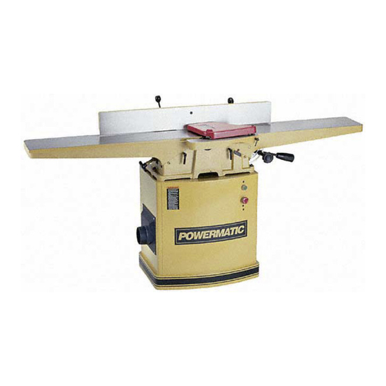
Page 8: Features
FEATURES of the 60B Jointer... -
Page 9: Receiving
RECEIVING Open both shipping crates and check for shipping damage. Report any damage immediately to your distributor and/or shipping agent. Before operating your jointer, read this instruction manual thoroughly for assembly, maintenance and safety instructions. Crate #1 contents 1 jointer stand with motor 1 door 1 dust collector adapter Crate #2 contents... -
Page 10: Aligning Pulleys
Secure table to stand with three 3/8-16x2-3/8 bolts, six 3/8 flat washers, three 3/8 lock washers and three 3/8 hex nuts (Fig. 6). Tighten with 9/16" wrench. ALIGNING PULLEYS Place a straight edge against the motor pulley and cutterhead pulley to make sure they are aligned. -
Page 11: Mouting Pulley Guard
MOUNTING PULLEY GUARD Place the pulley guard (A, Fig. 9) as shown and secure with knob (B, Fig. 9). MOUNTING DUST ADAPTOR Place the dust adaptor over the opening in the jointer stand, and secure with four 1/4-20 x 1/2 pan head screws and four 1/4 flat washers (Fig. -
Page 12: Adjustments
ADJUSTMENTS WARNING: Disconnect machine from power source before making adjust- ments. Tools required 8mm & 12mm wrenches 4mm hex wrench machinist's protractor or adjustable square steel straight edge CUTTER GUARD Removing Guard: Some adjusting procedures, as well as rabbeting operations, will require removal of the guard. Simply loosen handle on rabbeting ledge (Fig. -
Page 13: Installing Knives
INSTALLING KNIVES CAUTION: Use care when working with or around sharp knives. Make sure power to the machine has been disconnected. When installing new knives, remove only one knife at a time. Clean the knife slot and install the new knife. Adjust and lock new knife in cutterhead assembly before proceeding to next knife. -
Page 14: Leveling Tables
Rotate the cutterhead to the next slot by turning the motor pulley, and repeat step #6, only making the knives snug. Repeat for the third knife. NOTE: Do not grab the cutterhead itself to rotate it. The tightening process should continue at least two more times, each time tightening the screws more on all three knives. -
Page 15: Adjusting Depth Of Cut
Tighten the gib screws (A, Fig. 16) then back off approximately 1/4 turn or until the table moves freely, and reset the lock nuts on the gib screws. If table will not line up: Remove gib screws and table locking handle and remove gib. -
Page 16: Setting Outfeed Table
SETTING OUTFEED TABLE For accurate work in most jointing operations, the outfeed table must be exactly level with the knives at their highest point of revolution. Raise the outfeed table to its highest point, and place a straight edge across it. Turn the cutterhead until one knife is at its highest point. -
Page 17: Spring Cutting
SPRING CUTTING To spring cut, the outfeed table is lowered below the level of the cutterhead, as in Fig. 21. Loosen both gib screws (A-Fig. 21) on the outfeed table. Amount of end-drop is controlled with the table lock screw (B-Fig. 21). Tighten handle to reduce amount of drop. -
Page 18: Fence Stops
FENCE STOPS Periodically check the 90 degree and 45 degree tilt accuracy of the fence with an adjustable square or machinist's protractor. If adjustments are necessary, proceed as follows: 90 degree stop: The 90 degree stop is controlled by the screw (D, Fig. -
Page 19: Basic Jointer Operation
Tilt the fence until it is flush with the protractor. Rotate the screw (F, Fig. 23) to the proper height. Tighten hex nut (F, Fig. 23) and locking handle (B, Fig. 23). BASIC JOINTER OPERATION NOTE: If you are inexperienced at jointing, use scrap pieces of lumber to check settings and get the feel of operations before attempting regular work. -
Page 20: Hand Placement
HAND PLACEMENT At the start of the cut, the left hand holds the work firmly against the infeed table and fence while the right hand pushes the work toward the knives. After the cut is under way, the new surface rests firmly on the outfeed table. -
Page 21: Edge Jointing
EDGE JOINTING This is the most common operation for the jointer. Set guide fence square with the table. Depth of cut should be the minimum required to obtain a straight edge. Do not make cuts deeper than 1/8" in a single pass. Hold the best face of the piece firmly against the fence throughout the feed. -
Page 22: Taper Cuts
TAPER CUTS A useful jointer operation is cutting an edge to a taper. The method can be used on a wide variety of work. Tapered legs of furniture are a common example. Instead of laying the piece on the infeed table, lower the forward end of the work onto the outfeed table. -
Page 23: Maintenance
When rabbeting long pieces, follow the same procedure for surfacing long pieces (page 20) MAINTENANCE WARNING: Disconnect machine from power source before performing maintenance. The table and fence surfaces must be kept clean and free of rust for best results. Some users prefer a paste wax coating. -
Page 24: Cutterhead Repairs
Clamp a block of wood across the infeed table so that the end of a sharpening stone may be placed against the block during jointing operation (Fig. 33). This will help prevent kickback of the stone. Re-connect power and turn machine on. Keep hands clear of turning cutterhead. -
Page 25: Table Removal
Remove rabbeting ledge by loosening the two hex cap screws and washers (A, Fig. 35). Loosen the two bolts (B, Fig. 35) that secure the cutterhead to the bed – these are accessed from the underside of the bearing blocks. Lift cutterhead straight up from base. -
Page 26: Trouble-Shooting
TROUBLE-SHOOTING Model 60B Jointer PROBLEM POSSIBLE CAUSE SOLUTION Machine will not start, 1. No incoming power. 1. Verify unit is connected to power. or repeatedly trips breaker or blows fuses. 2. Low voltage. 2. Check power source for sufficient voltage. -
Page 27: Optional Accessories
2. Knives cutting against grain. 2. Cut with the grain. 3. Moisture content of wood too high. 3. Use different wood. OPTIONAL ACCESSORIES for 60B Jointer 2042376 ..... Mobile Base 6427002 ..... Knives (set of 3) 6285917 ..... Push Block... - Page 28 Description Size Qty.... 60B-100....Fence Assembly (Items 1 thru 33).............. 1 1 ..6296143 ....Locking Bolt ....................1 2 ..6296066 ....Flat Washer ..........1/2”x1-1/8”D ......1 3 ..6296067 ....Stop Block ....................1 4 ..
-
Page 29: Fence Assembly
Fence Assembly (60B Jointer) -
Page 30: Base & Table Assembly
39 ..6296035 ....Lock Plate....................1 40 ..6296036 ....Plate ......................1 41 ..60B-241....Front Table ....................1 42 ..6296038 ....Handwheel ....................1 43 ..6296039 ....Pan Head Screw ........... 5/16”-18x1/2” ......1 44 .. - Page 31 69 ..6296088....Spring Pin .............4x14........1 70 ..6296086....Base Slide ....................1 71 ..60B-271 ....Stop Handle ....................1 ....60B-270 ....Cutterhead Guard Assembly (Items 72 thru 77) ...........1 72 ..60B-272 ....Warning Label ....................1 73 ..60B-273 ....Cutterhead Guard..................1 74 ..JSG96-223...
- Page 32 Base Assembly (60B Jointer)
-
Page 33: Cutterhead Assembly
PARTS LIST: Cutterhead Assembly (60B Jointer) Index Part Description Size Qty.....60B-300 ....Cutterhead Assembly (Items 1 thru 5, and 10 thru 13) .........1 1..6296046....Knife......................3 2..6296153....Knife Gib ....................3 3..6296048....Key..............5x5x25 ........1 4..6296049....Ball Bearing...........6203-2NSE ......2 5..6296050....Bearing Housing ..................2 6..6296152.... -
Page 34: Cutterhead Assembly
Cutterhead Assembly (60B Jointer) -
Page 35: Stand Assembly
....60B-415MFC..Motor Fan Cover (not shown) ..............1 ....60B-415CS ..Centrifugal Switch (not shown) ..............1 ....60B-415MDC ..Motor Dustproof Cover (not shown) ............1 ....60B-415CC ..Capacitor Cover (not shown) ..............2 ....60B-415SC ..Starting Capacitor (not shown).......400MFD, 125VAC ....1 ....60B-415RC .. - Page 36 35 ..TS-073203.... Star Washer....................2 36 ..6510001 ....Hex Nut ............#10-24 ........2 37 ..3312341 ....Powermatic Logo ..................1 38 ..6296150 ....Warning Label ................... 1 39 ..6823013 ....Stripe ..................... 8 ft.
-
Page 37: Stand Assembly
Stand Assembly (60B Jointer) -
Page 38: Electrical Schematics
ELECTRICAL SCHEMATIC (60B Jointer) 230 Volt 1 Phase... -
Page 39: 230 Volt 3 Phase
ELECTRICAL SCHEMATIC (60B Jointer) 230 Volt 3 Phase... -
Page 40: 460 Volt 3 Phase
ELECTRICAL SCHEMATIC (60B Jointer) 460 Volt 3 Phase... -
Page 41: Preventive Maintenance
Preventive Maintenance Checklist for Model 60B Jointer Work area around machine marked off clearly. Non-skid floor strips in area where operator normally stands. Kickback path not aimed at other work areas, aisles or doorways. Various types of push pads and blocks readily available to operator. - Page 43 Locating the stock number of the part(s) required from your parts manual will also expedite your order. Phone No.: (800) 274-6848 Fax No. (800) 274-6840 If you are calling from Canada, please call 800-238-4746 E-mail: powermatic@wmhtoolgroup.com Website: www.powermatic.com...
- Page 44 05/03 WMH Tool Group 427 Sanford Road LaVergne, TN 37086 Phone:(800) 274-6848 Fax: (800) 274-6840 E-mail: powermatic@wmhtoolgroup.com Website: www.powermatic.com Powermatic ALL RIGHTS RESERVED...
Need help?
Do you have a question about the 60B and is the answer not in the manual?
Questions and answers