
Subscribe to Our Youtube Channel
Related Manuals for Husqvarna 16


Summary of Contents for Husqvarna 16
- Page 1 Operator´s manual Rider 16 Please read these instructions carefully and make sure English you understand them before using the machine.
- Page 2 Svenska –...
-
Page 3: Table Of Contents
CONTENTS Operator’s Manual for Rider 16 Adjusting the brake ... 22 Checking and adjustment of throttle wire ... 23 Replacement of fuel filter ... 23 Replacement of air filter ... 24 Checking the fuel pump’s air filter ... -
Page 4: Introduction
INSTRUCTION Dear customer Thank you for choosing a Husqvarna Rider. Husqvarna Riders are built to a unique design with a front- mounted cutting unit and a patented rear-wheel steering system. Riders are designed for maximum efficiency even in small or confined areas. The closely grouped controls and pedal-operated hydrostatic transmission also contribute to the performance of this machine. -
Page 5: Safety Instructions
SAFETY INSTRUCTIONS Good service Husqvarna products are sold all over the world and only through servicing dealers. This is to ensure that you, the customer, get the best support and service. Before the machine is delivered it undergoes inspection and is adjusted by your dealer. -
Page 6: Explanation Of Symbols
EXPLANATION OF SYMBOLS These symbols are on the machine and in the operator’s manual. Study them carefully so that you know what they mean. Reverse Neutral Fast Oil pressure Cutting height Hydrostatic free wheel Use eye and hearing protection Noise emission to surroundings in accordance with the directive of the European Community. -
Page 7: Safety Instructions
SAFETY INSTRUCTIONS Safety instructions These instructions are for your safety. Read them carefully. WARNING! The inserted symbol means that important safety instructions need to be observed. It applies to your safety. General use • Read all the instructions in this operator’s manual and on the machine before you start it. - Page 8 SAFETY INSTRUCTIONS • Take care when rounding a fixed object, so that the blades do not hit it. Never run the machine over foreign objects. • Only use the machine in daylight or in other well-lit conditions. Keep the machine at a safe distance from holes or other irregularities in the ground.
-
Page 9: Driving On Slopes
SAFETY INSTRUCTIONS Driving on slopes Driving on slopes is one of the operations where the risk of the driver losing control of the machine or of it overturning is the greatest; this can result in serious injury or death. All slopes demand extra care. -
Page 10: Children
SAFETY INSTRUCTIONS Children • Serious accidents may occur if you fail to be on your guard for children in the vicinity of the machine. Children are often attracted to the machine and mowing. Never assume that children will remain where you last saw them. •... - Page 11 SAFETY INSTRUCTIONS • If leaks arise in the fuel system, the engine must not be started until the problem has been resolved. • Store the machine and fuel in such a way that there is no risk that leaking fuel or fumes can cause any damage.
-
Page 12: Transport
SAFETY INSTRUCTIONS • Never use the machine indoors or in spaces lacking proper ventilation. Exhaust fumes contain carbon monoxide, an odourless, poisonous and highly dangerous gas. • Stop and inspect the equipment if you run over or into anything. If necessary, make repairs before starting. -
Page 13: Presentation
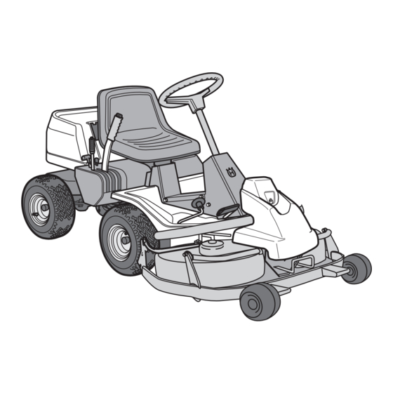
Presentation Congratulations on your choice of a top quality product which you will enjoy for many years. These instructions describe the Rider 16. This rider mower is equipped with a 15.5 horsepower Briggs & Stratton engine. The power transmission from the engine is handled by a hydrostatic gear box which enables stepless varia- tion of the speed with the foot pedals. -
Page 14: Throttle/Choke Lever
Throttle and Choke lever The engine speed is adjusted with the throttle control, and thereby also the rotation speed of the blades. The control is also used to activate the choke function. When the choke is used the engine receives a richer mixture of fuel and air, which simplifies cold start. -
Page 15: Cutting Unit
Cutting unit The Rider 16 can be fitted with four different cutting units. Rear ejector - 970 mm Side ejector - 970 mm BioClip - 900 mm, 1030 mm Combi - 1120 mm Combi See ”Maintenance \ Checking the Blades” for identification of the cutting unit. -
Page 16: Lever For Adjustment Of Cutting Height
Lever for adjustment of cutting height With this lever the cutting height can be adjusted to 9 different positions (4-90 mm, 45-80 mm Bioclip). Unit with side/rear ejection/Combi, 40-90 mm. BioClip unit, 45-95 mm. Seat The seat has a jointed attachment on the front edge and can be tipped forward. -
Page 17: Driving
• Read the safety instructions and information on the location and function of the controls before starting (see pages 5-14). • Conduct daily maintenance before starting (see maintenance schedule on page 20). Adjust the seat to the required position. Starting the engine 1. - Page 18 Warm engine: 4. Set the throttle control midway between position 1 and 2. 5. Turn the ignition key to start position. IMPORTANT INFORMATION Do not run the starter for more than about 5 seconds at a time. If the engine does not start, wait about 10 seconds before trying again.
-
Page 19: Driving The Machine
Driving the machine 1. Release the parking brake by pressing down the brake pedal. 2. Carefully press down one of the pedals until the correct speed is reached. To drive forwards: press down pedal (1). To reverse: press down pedal (2). 3. -
Page 20: Cutting Tips
4. Push in the lock button on the lift lever and lower down the cutting unit. IMPORTANT INFORMATION The service-life of the drive belts increases considerably if the engine is run at low speed when engaging the blades. For this reason do not increase the throttle until the cutting unit has been lowered to the cutting position. -
Page 21: Stopping The Engine
WARNING! Never drive the machine on ground with a slope of more than 15°. Mow slopes upwards and downwards, never across. Avoid sudden changes in direction. Stopping the engine Preferably allow the engine to idle for a minute to obtain normal working temperature before stopping it if it has been working hard. -
Page 22: Maintenance
The following is a list of the maintenance which should be conducted on the machine. For the items which are not described in these instructions go to an authorised service workshop. Maintenance Check the engine’s oil level Check the engine’s cooling air inlet Check the fuel pump’s air filter Check the steering wires Check the battery... -
Page 23: Dismantling Of The Machine Hoods
Dismantling of the machine hoods Engine hood The engine is accessible for servicing when the engine hood is lifted up. Tilt the seat forward, release the rubber strap under the seat, and tilt the hood backwards. Front hood Release the clip on the front hood and lift off the fender. -
Page 24: Checking And Adjusting The Steering Wires
Checking and adjustment of the steering wires The steering is controlled by means of wires. These can in time become slack, which implies that the adjustment of the steering becomes altered. Check and adjust the steering as follows: 1. Dismantle the frame-plate by releasing the screws (two on each side). -
Page 25: Checking And Adjustment Of Throttle Wire
Checking and adjustment of the throttle wire If the engine does not respond as it should do when the throttle lever is moved or if the top speed is not reached, the throttle wire may need adjusting. 1. Loosen the clamping screw (by the arrow), and slide the throttle to the choke position. -
Page 26: Replacing The Air Filter
Replacing the air filter If the engine seems to lack power or goes irregularly the reason may be that the air filter is clogged. It is therefore important to replace the air filter at regular intervals (see ”Maintenance schedule” on page 20 for correct service interval). -
Page 27: Checking The Fuel Pump's Air Filter
Remove the ignition cable shoe and clean around the spark plug. Remove the spark plug with a 13/16" (21 mm) spark plug socket wrench. Check the spark plug. Replace the spark plug if the electrodes are burned or if the insulation is cracked or damaged. -
Page 28: Inspecting The Safety System
Inspecting the safety system The Rider is equipped with a safety system that prevents starting or driving under the following conditions: The engine should only be possible to start when the cutting unit is in its raised position and the hydrostat pedals are in the neutral position. -
Page 29: Checking The Tyre Pressure
Checking the tyre pressure The tyre pressure should be 60 kPa (0.6 kp/cm round. To improve driving the pressure on the rear tyres can be reduced to 40 kPa (0.4 kp/cm2). The maximum tyre pressure is 100 kPa (1.0 kp/cm IMPORTANT INFORMATION Different tyre pressures on the front tyres will result in the blades cutting the grass... -
Page 30: Fitting The Cutting Unit
Fitting the cutting unit 1. Place the Rider on a flat surface and apply the parking brake. Check that the lever for setting the cutting height is in the lowest position. Make sure the support wheels are fitted to the cutting unit (1). -
Page 31: Checking And Adjustment Of Cutting Unit's Ground Pressure
Checking and adjustment of the cutting unit’s ground pressure To achieve the best cutting results the cutting unit should follow the underlying surface without pres- sing too hard against it. The pressure is adjusted with a screw on each side of the machine. -
Page 32: Adjusting The Parallelism Of The Cutting Unit
Adjusting the parallelism of the cutting unit 1. Remove the front hood and right-hand fender, as described on page 21. 2. Undo the nuts on the lift strut. 3. Unscrew the strut (anticlockwise) to lower the rear edge of the hood. Screw the strut in (clockwise) to raise the rear edge of the hood. -
Page 33: Replacing The Cutting Unit Belts
Replacing the cutting unit belts Belt change on BioClip 103 There are two versions of BioClip 103. Version 1 has one toothed belt and version 2 has two. The toothed belts drive the blades and synchronise their rotation. The belts are located under a cover on top of the cutting unit. - Page 34 5. Version 2: Assembly: First fit the lower belt and then the upper belt. Ensure the blades are positioned as set out in the diagram, at 90 degrees to each other, otherwise the belts must be adjusted. When the blade bearings are loose the belts can be moved around to the next tooth.
-
Page 35: Service Position For Cutting Unit
Service position for cutting unit The cutting head can be placed in the service position to provide easy access for cleaning, repairs and servicing. In the service position the cutting unit is raised and locked in the vertical position. Placing in service position 1. - Page 36 4. Fit the support wheels on either side of the rear of the cutting unit. WARNING! Wear protective glasses when dismantling the cutting unit. The spring which tensions up the belt can go off and cause personal injury. 5. Disengage the spring from the drive belt tensioning wheel.
-
Page 37: Restoring From Service Position
WARNING! Observe caution to avoid trapping your hand. 8. Lift off the drive belt (1). Then pull out the pin (2). 9. Pull the frame forwards and refit the pin. 10.Grasp the front edge of the cutting unit, pull out and raise into the service position. -
Page 38: Checking The Blades
Checking the blades To achieve the best mowing results it is important that the blades are undamaged and well-sharpened. Check that the blades’ attachment screws are tight. IMPORTANT INFORMATION Replacing or sharpening the blades should be conducted by an authorised service workshop. -
Page 39: Replacing The Break-Pin (Bioclip)
Replacing the break-pin (BioClip) The blades are fitted with a break-pin to protect the BioClip unit and its drive when colliding with obstacles. A domed, spring friction washer is fitted to each blade bolt. The washer must always be replaced with a new washer if the blade bolt is loosened. -
Page 40: Lubrication
Check the engine’s oil level Check the oil level in the engine when the machine is horizontal. Fold open the engine cover. Release the dip stick and pull out. Wipe off the oil and insert again. The dip stick must be fully screwed down. Now release the dip stick again and pull out. -
Page 41: Checking The Transmission's Oil Level
Check the transmission’s oil level 1. Remove the transmission cover. Loosen both screws (one on each side) and lift off the trans- mission cover. 2. Check that there is oil in the transmission’s oil tank. Fill if necessary with engine oil SAE 10W/ 30 (class SF–CC). -
Page 42: Trouble Shooting Schedule
TROUBLE SHOOTING SCHEDULE Problem Engine will not start. Starter does not pull round engine. Engine does not run smoothly. Engine seems to have no power. Engine overheats. Battery does not charge. Machine vibrates. Uneven mowing. – English Procedure • Fuel tank empty. •... -
Page 43: Storage
Winter storage At the end of the season the machine should immediately be put in order for storage, also if it is going to stand idle for more than 30 days. Fuel which is left to stand for long periods (30 days or more) can leave tacky deposits which can block the carburettor and interfere with the engine. -
Page 44: Technical Data
2145 mm 1050 mm 1060 mm 247-260 kg including unit 855 mm Front 715 mm, rear 625 mm 16 x 6.50 x 8 60 kPa (0.6 kp/cm 15° Briggs & Stratton model 28N707 11.4/15.5 kW/h.p. 465 cm Min. 85 octane unleaded... -
Page 45: Eu Declaration Of Conformity
Husqvarna AB, SE-561 82 Huskvarna, Sweden, tel: +46-36-146500, declares under sole responsibility that the Husqvarna Rider 16, from 2002’s serial numbers and onwards (the year is clearly stated in plain text on the rating plate with subsequent serial number), complies with the requirements of the COUNCIL’S DIRECTIVES: - of June 22, 1998 ”relating to machinery”... -
Page 46: Pre-Delivery Service
SERVICEJOURNAL RIDER 16 Work done Pre-delivery service 1. Top up battery with acid and recharge for four hours. 2. Fit steering wheel, seat and any optional equipment. 3. Adjust cutting unit: Adjust the lifting springs (the “weight” of the cutting unit should be 12-15 kg). -
Page 47: Service Journal
SERVICEJOURNAL Date, mileage, stamp, sign Work done English –... - Page 48 SERVICEJOURNAL Date, mileage, stamp, sign Work done – English...
- Page 49 SERVICEJOURNAL Date, mileage, stamp, sign Work done English –...
- Page 50 SERVICEJOURNAL Date, mileage, stamp, sign Work done ´+H$|¶6k¨...
- Page 51 English –...
- Page 52 114 00 49-26 ´+H$|¶6k¨ 2002W09...
Need help?
Do you have a question about the 16 and is the answer not in the manual?
Questions and answers