Table of Contents
Advertisement
Quick Links
Advertisement
Table of Contents

Subscribe to Our Youtube Channel
Related Manuals for HIKVISION DS-2CD4212F


Summary of Contents for HIKVISION DS-2CD4212F
- Page 1 Camera Network Bullet Camera Quick Operation Guide UD.6L0201B1307A01...
- Page 2 Thank you for purchasing our product. If there are any questions, or requests, please do not hesitate to contact the dealer. About This Document This manual applies to the following camera models. Model DS-2CD4212F-(I)(Z)(H)(S) DS-2CD4212FWD-(I)(Z)(H)(S) DS-2CD4224F-(I)(Z)(H)(S) DS-2CD4232FWD-(I)(Z)(H)(S) This manual may contain several technical incorrect places or printing errors, and the content is subject to change without notice.
-
Page 3: Regulatory Information
Network Bullet Camera·Quick Operation Guide Regulatory Information FCC Information FCC compliance: This equipment has been tested and found to comply with the limits for a digital device, pursuant to part 15 of the FCC Rules. These limits are designed to provide reasonable protection against harmful interference when the equipment is operated in a commercial environment. - Page 4 Network Bullet Camera·Quick Operation Guide 2012/19/EU (WEEE directive): Products marked with this symbol cannot be disposed of as unsorted municipal waste in the European Union. For proper recycling, return this product to your local supplier upon the purchase of equivalent new equipment, or dispose of it at designated collection points.
-
Page 5: Safety Instruction
Network Bullet Camera· Quick Operation Guide Safety Instruction These instructions are intended to ensure that user can use the product correctly to avoid danger or property loss. The precaution measure is divided into “Warnings” and “Cautions” Warnings: Serious injury or death may occur if any of the warnings are neglected. - Page 6 Network Bullet Camera· Quick Operation Guide ● Do not connect several devices to one power adapter as adapter overload may cause over-heating or a fire hazard. ● Please make sure that the plug is firmly connected to the power socket. When the product is mounted on wall or ceiling, the device shall be firmly fixed.
- Page 7 Network Bullet Camera· Quick Operation Guide ● Do not place the camera in extremely hot, cold (the operating temperature shall be-30℃~+60℃,or -40°C ~ 60°C if the camera model has an “H” in its suffix), dusty or damp locations, and do not expose it to high electromagnetic radiation.
-
Page 8: Table Of Contents
Network Bullet Camera· Quick Operation Guide Table of Contents 1 Appearance Description ..............8 Camera Description ............8 Wiring ................9 2 Installation ..................11 3 Setting the Network Camera over the LAN ........18 4 Accessing via Web Browser ............24... -
Page 9: Appearance Description
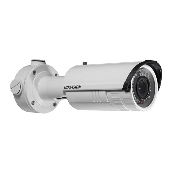
Network Bullet Camera· Quick Operation Guide 1 Appearance Description 1.1 Camera Description The overview of the network bullet camera is shown below: Figure 1-1 Overview Table 1-1 Description Description Description Sun Shield Bracket... -
Page 10: Wiring
Network Bullet Camera· Quick Operation Guide Description Description Junction Box Reset SD Card Slot Front Box Analog Video Output 1.2 Wiring The wiring varies according to the different models of bullet camera. Figure 1-2 Wiring (A) Table 1-2 Description (A) Description Power supply interface 10M/100M self-adaptive Ethernet interface... - Page 11 Network Bullet Camera· Quick Operation Guide Figure 1-3 Wiring (B) Table 1-3 Description (B) Description AUDIO IN, G: Audio input interface AUDIO OUT, G: Audio output interface IN, G: Alarm input interface 1A, 1B: Alarm output interface D+, D-: RS-485 interface Power supply interface 10M/100M self-adaptive Ethernet interface...
-
Page 12: Installation
Network Bullet Camera· Quick Operation Guide 2 Installation Before you start: Make sure the device in the package is in good condition and all the assembly parts are included. Make sure all the related equipment is power-off during the installation. - Page 13 Network Bullet Camera· Quick Operation Guide ● Make sure that there is no reflective surface too close to the camera lens. The IR light from the camera may reflect back into the lens causing reflection. ● The foam ring around the lens must be seated flush against the inner surface of the bubble to isolate the lens from the IR LEDS.
- Page 14 Network Bullet Camera· Quick Operation Guide 3. Fix the junction box to the wall with the expansion screws. Junction Box Figure 2-2 Install the Junction Box 4. Route the cables of the camera. Route the cables through the junction box and the cable hole if there is a cable hole drilled on the ceiling.
- Page 15 Network Bullet Camera· Quick Operation Guide 5. Hook the camera to the junction box with the safety rope. 6. Tighten the screws to fix the camera to the junction box. Figure 2-3 Fix the Camera to the Junction Box 7. Loosen the screws on the bracket to adjust the camera to the desired surveillance angle and then tighten the screws to fix the camera.
- Page 16 Network Bullet Camera· Quick Operation Guide Pan Adjust Nut Tilt Adjust Nut Figure 2-4 Adjust Monitoring Angle Please loosen the screws slightly until you can adjust the camera and do not remove the screws from the bracket. 8. Loosen the lock screw on the sun shield and remove the sun shield.
- Page 17 Network Bullet Camera· Quick Operation Guide Romove the Front Box Zoom Lever Focus Lever Remove the Sun Shield Figure 2-5 Lens Adjustment For the device supports electronic lens, you can only adjust the camera to the proper surveillance angle via 3-axis adjustment, then adjust the zoom and focus by the PTZ control from the client software or web browser.
- Page 18 Network Bullet Camera· Quick Operation Guide For some projects have strict demands on the water-proof, you may need to install a water-proof rubber case (purchased separately) to the foldable position of the bracket to protect it from water. See the figure below.
-
Page 19: Setting The Network Camera Over The Lan
Network Bullet Camera· Quick Operation Guide 3 Setting the Network Camera over the Purpose: To view and configure the camera via LAN (Local Area Network), you need to connect the network camera in the same subnet with your PC. Then, install the SADP or PCNVR software to search and change the IP of network camera. - Page 20 Network Bullet Camera· Quick Operation Guide Use PCNVR software and to list the online devices. Please refer to the user manual of PCNVR client software for detailed information. 2. Change the IP address and subnet mask to the same subnet as of your PC.
- Page 21 Network Bullet Camera· Quick Operation Guide Figure 3-2 Search Online Devices Device can be searched and displayed in the list in 15 seconds after it goes online; it will be removed from the list in 45 seconds after it goes offline. Search online devices manually:...
-
Page 22: Modify Device Information
Network Bullet Camera· Quick Operation Guide You can also click to refresh the online device list manually. The newly searched devices will be added to the list. You can click on each column heading to order the information; you can click to show the device table and hide the network parameter panel on the right side, or click... - Page 23 Network Bullet Camera· Quick Operation Guide Figure 3-3 Select a Device Figure 3-4 Modify Network Parameters 3. Enter the IP address of network camera in the address field of the web browser to view the live video.
- Page 24 Network Bullet Camera· Quick Operation Guide The default value of the IP address is “192.0.0.64”. The default user name is “admin”, and password is “12345”. For accessing the network camera from different subnets, please set the gateway for the network camera after you log in.
-
Page 25: Accessing Via Web Browser
Network Bullet Camera· Quick Operation Guide 4 Accessing via Web Browser System Requirement: Operating System: Microsoft Windows XP SP1 and above version / Vista / Win7 / Server 2003 / Server 2008 32bits CPU: Intel Pentium IV 3.0 GHz or higher RAM: 1G or higher Display: 1024×768 resolution or higher Web Browser: Internet Explorer 6.0 and above version, Apple Safari... - Page 26 Network Bullet Camera· Quick Operation Guide Figure 4-1 Login Interface 5. Install the plug-in before viewing the live video and managing the camera. Please follow the installation prompts to install the plug-in. You may have to close the web browser to finish the installation of the plug-in.
- Page 27 Network Bullet Camera· Quick Operation Guide Figure 4-2 Download Plug-in Figure 4-3 Install Plug-in (1)
- Page 28 Network Bullet Camera· Quick Operation Guide Figure 4-4 Install Plug-in (2) 6. Reopen the web browser after the installation of the plug-in and repeat steps 2-4 to login. For detailed instructions of further configuration, please refer to the user manual of network camera.
Need help?
Do you have a question about the DS-2CD4212F and is the answer not in the manual?
Questions and answers