Table of Contents
Advertisement
Operator's Manual
826 SWE
1130 SWE
IMPORTANT: Read safety rules and instructions carefully before operating equipment.
Warning:
This unit is equipped with an internal combustion engine and should not be used on or near any unimproved forest-
covered, brush-covered or grass-covered land unless the engine's exhaust system is equipped with a spark arrester meeting
applicable local or state laws (if any). If a spark arrester is used, it should be maintained in effective working order by the operator.
In the State of California the above is required by law (Section 4442 of the California Public Resources Code). Other states may have
similar laws. Federal laws apply on federal lands. A spark arrester for the muffler is available through your nearest engine authorized
service dealer or contact the service department, P.O. Box 368023 Cleveland, Ohio 44136-9722.
CUB CADET CORP. P.O. BOX 368023 CLEVELAND, OHIO 44136-9722
FORM NO. 770-10026A
PRINTED IN U.S.A.
(12/99)
Advertisement
Table of Contents

Related Manuals for Cub Cadet 826 SWE


Summary of Contents for Cub Cadet 826 SWE
- Page 1 Federal laws apply on federal lands. A spark arrester for the muffler is available through your nearest engine authorized service dealer or contact the service department, P.O. Box 368023 Cleveland, Ohio 44136-9722. CUB CADET CORP. P.O. BOX 368023 CLEVELAND, OHIO 44136-9722 FORM NO. 770-10026A PRINTED IN U.S.A.
-
Page 2: Table Of Contents
Before you start assembling your new equipment, please locate the model plate on the equipment and copy the information from it in the space provided below. The information on the model plate is very important if you need help from your local authorized Cub Cadet dealer. -
Page 3: Important Safe Operation Practices
SECTION 1: IMPORTANT SAFE OPERATION PRACTICES This Warning symbol points out important safety instructions which, if not followed, could endanger the personal safety and/or property of yourself and/or others. Read and follow all instructions in this manual before attempting to operate your snow thrower. Failure to comply with these instructions may result in personal injury. -
Page 4: Maintenance And Storage
• Take all possible precautions when leaving the unit • Use only attachments and accessories approved by unattended. Disengage the collector/impeller, shift the manufacturer of snow thrower (such as wheel into neutral, stop the engine, and remove the key. weights, counter weights, cabs, etc.). •... -
Page 5: Loose Parts
SECTION 2: LOOSE PARTS The snow thrower is shipped with the following loose parts in the carton. Please remove all loose parts from the carton before discarding it. See Figure 1 to identify the parts, noting that these parts may be referred to again in the following sections of the manual. -
Page 6: Final Adjustments
• If not already attached, slip the cables that run from the handle panel to the chute into the cable guide located on top of the engine. See Figure 4. Cable Guide Figure 4 “Z” End Final Adjustments Auger Control Adjustment Jam Nut Check the adjustment of the auger control as follows: •... -
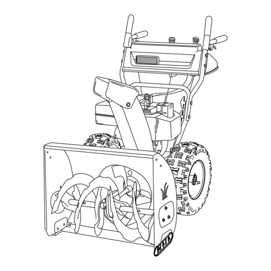
Page 7: Know Your Snow Thrower
Adjust skid shoes as follows: • Loosen, but do NOT remove, the three hex nuts which fasten the skid shoe to the auger housing. • Move the skid shoe to the desired position. NOTE: Make certain the entire bottom surface of the skidshoe is against the ground to avoid uneven wear on the skid shoes. -
Page 8: Operating Your Snow Thrower
Wheel Steering Controls the Open (vertical) position before attempting to start the engine. The left and right wheel steering controls are located on the underside of the handles and are used to assist in steering the snow thrower. See Figure 7. Squeeze the right wheel steering control when turning right, squeeze Primer the left control when turning left. - Page 9 is grounded and a three-hole receptacle is not Electric Starter: Connect the power cord to the available at the point your starter will normally be switch box on the engine, then connect to a 120 used, one should be installed by a licensed volt AC receptacle.
-
Page 10: Making Adjustments
Operating Tips • Discharge the snow downwind whenever possible. • Slightly overlap each previous path. NOTE: Allow the engine to warm up for a few minutes. • Set the skid shoes 1/4" below the shave plate for The engine will not develop full power until it reaches normal usage. -
Page 11: Maintaining Your Snow Thrower
Shift Rod Adjustment elbow on its lower end aligns with the hole found in the lower shift rod. To adjust the shift rod, proceed as follows. • Reconnect the upper shift rod to the lower shift rod • Remove the hairpin clip and slide the clutch rod by reinserting the hairpin clip removed earlier and connector up, to separate the upper shift rod from sliding clutch rod connector back down into place. -
Page 12: Service
of operation. The cams can be accessed beneath the using Shell Alvania grease EPR00, part number 737- handle panel. Use a multi-purpose automotive grease. 0168. Refer to Figure 12. Gear Case Do not overfill the gear case. Damage to IMPORTANT: The gear case is lubricated with grease at the factory. -
Page 13: Replacing Friction Wheel Rubber
• Replace both auger drive belts by following instructions in reverse order. Friction Wheel Wheel Drive Plate Drive Pulley Drive Belt Auger Drive Wheel Stop Bolt Drive Pulley Belt Idler Pulley Idler Support Bracket Pulley Auger Figure 16 Drive Belts Replacing Friction Wheel Rubber Frame The rubber on the friction wheel is subject to wear and... - Page 14 • Reassemble the new friction wheel rubber to the Shift Rod Assy friction wheel plates and hub, tightening the six Axle Shaft screws in rotation and with equal force. Hex Shaft • Position the friction wheel assembly up onto the pin of the shift rod assembly, and slide the hex shaft through the friction wheel assembly.
-
Page 15: Troubleshooting
SECTION 9: TROUBLESHOOTING Problem Cause Remedy Engine fails to start 1. Fuel tank empty, or stale fuel. 1. Fill tank with clean, fresh gasoline. Fuel becomes stale after thirty days. 2. Blocked fuel line. 2. Clean the fuel line. 3. Choke not in the ON position 3. -
Page 16: Parts List
Wheel Assy Comp: 16” x 6.5” (1130 SWE) 738-0994A Axle: .75” dia. x 12.201” Lg. 734-1530 Tire, Snow Hog, 16.5 x 4.8 - 4 (826 SWE) 734-1525 Tire, Snow Hog, 16.0 x 6.5 x 8 (1130 SWE) 734-1708 Rim Assembly (826 SWE) - Page 17 Models 826 SWE / 1130 SWE Ref. Part No. Part Description 618-0123 RH Housing (Incl. Ref. 17, 18) 618-0418 LH Housing w/Fitting (Incl. Ref. 17, 18) 710-0642 Self Tapping Screw, 1/4-20 x .75 711-1024 Spiral Axle, 30” (1130 SWE) 711-0909 Spiral Axle, 26”...
- Page 18 Models 826 SWE / 1130 SWE reference only reference only...
- Page 19 Models 826 SWE / 1130 SWE Ref. Ref. Part No. Part Description Part No. Part Description 684-0008A Shift Arm Assembly 736-0159 5/16 Washer 710-0262 Carriage Bolt 5/16-18 x 1.5” 736-0242 Belleville Washer 710-0449 Carriage Bolt 5/16-18 x 2.25” 736-0506 Special Washer 710-0788 TT Screw 1/4-20 x 1”...
- Page 20 Models 826 SWE / 1130 SWE...
- Page 21 Models 826 SWE / 1130 SWE Ref. Ref. Part No. Part Description Part No. Part Description 712-0116 Lock Jam Nut 3/8-24 736-0463 Flat Washer 756-0178 Flat Idler 784-0399 Bearing Housing w/Fitting 784-5632A Auger Idler Arm 710-0703 Carriage Screw 1/4-20 x .75...
- Page 22 Models 826 SWE / 1130 SWE...
- Page 23 Models 826 SWE / 1130 SWE Ref. Part No. Part Description 710-1652 Hex Washer Screw 1/4-20 x .625 731-1324 Belt Cover 732-0710 Extension Spring 710-0627 Hex Screw 5/16-24 x .75 710-3005 Hex Cap Screw 3/8-16 x 1.25 05896A Drive Clutch Idler Bracket...
- Page 24 Models 826 SWE / 1130 SWE 34 32 Drive Clutch Cable routed below axle and hooked here...
- Page 25 Models 826 SWE / 1130 SWE Ref. Ref. Part No. Part Description Part No. Part Description 618-0043 Dogg Assembly: RH 736-0169 Lock Washer 618-0044 Dogg Assembly: LH 784-5740 Retainer Shaft LH: Actuator Drive 618-0303B Shift Assembly: Steerable Drive 736-0351 Flat Washer 656-0012A Friction Wheel Disc Assy.
- Page 26 Models 826 SWE / 1130 SWE...
- Page 27 Models 826 SWE / 1130 SWE Optional Equipment Drift Cutters- Part Number:OEM-390-679 Tire Chains- Part Number:OEM-390-991 (826 SWE) Part Number:OEM-390-655 (1130 SWE)
-
Page 28: Cleveland, Ohio
How to obtain service Contact your authorized Cub Cadet servicing dealer who sold you your Cub Cadet equipment. If this dealer is not available, see the Consumer Yellow Pages under “lawn mowers” for the name of a dealer near you.
Need help?
Do you have a question about the 826 SWE and is the answer not in the manual?
Questions and answers