Table of Contents
Advertisement
OPERATOR'S MANUAL
IMPORTANT: READ SAFETY RULES AND INSTRUCTIONS CAREFULLY
Warning:
This unit is equipped with an internal combustion engine and should not be used on or near any unimproved forest-
covered, brush-covered or grass-covered land unless the engine's exhaust system is equipped with a spark arrester meeting
applicable local or state laws (if any). If a spark arrester is used, it should be maintained in effective working order by the operator.
In the State of California the above is required by law (Section 4442 of the California Public Resources Code). Other states may have
similar laws. Federal laws apply on federal lands. A spark arrester for the muffler is available through your nearest engine authorized
service dealer or contact the service department, P.O. Box 368023 Cleveland, Ohio 44136-9722.
CUB CADET CORP. P.O. BOX 368023 CLEVELAND, OHIO 44136-9722
PRINTED IN U.S.A.
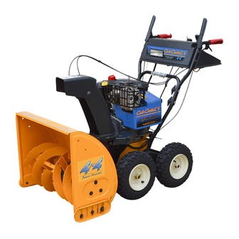
Snow Thrower
Models
826 SWE &1130 SWE
FORM NO.
770-10026C.fm
(11/01)
Advertisement
Table of Contents

Related Manuals for Cub Cadet 1130 SWE


Summary of Contents for Cub Cadet 1130 SWE
-
Page 1: Snow Thrower
Federal laws apply on federal lands. A spark arrester for the muffler is available through your nearest engine authorized service dealer or contact the service department, P.O. Box 368023 Cleveland, Ohio 44136-9722. CUB CADET CORP. P.O. BOX 368023 CLEVELAND, OHIO 44136-9722 PRINTED IN U.S.A. -
Page 2: Table Of Contents
Before you start assembling your new equipment, please locate the model plate on the equipment and copy the information from it in the space provided below. The information on the model plate is very important if you need help from your local authorized Cub Cadet dealer. -
Page 3: Section 1: Important Safe Operation Practices
SECTION 1: IMPORTANT SAFE OPERATION PRACTICES WARNING: This symbol points out important safety instructions which, if not followed, could endanger the personal safety and/or property of yourself and others. Read and follow all instructions in this manual before attempting to operate this machine. Failure to comply with these instructions may result in personal injury. -
Page 4: Maintenance And Storage
The clutch levers must operate easily in both directions and automatically return to the disengaged position when released. Never operate with a missing or damaged discharge chute. Keep all safety devices in place and working. Never run an engine indoors or in a poorly ventilated area. -
Page 5: Section 2: Assembling Your Snow Thrower
SECTION 2: ASSEMBLING YOUR SNOW THROWER NOTE: Any reference in this manual to the left or right side of the snow thrower is observed from the operator’s position. Unpacking • Remove screws from the top sides and ends of the shipping crate. -
Page 6: Final Adjustments
Final Adjustments Auger Control Adjustment Check the adjustment of the auger control as follows: • Push forward on the auger control until the small rubber bumper contacts the upper handle. There should be slack in the cable. See Figure 5 . •... -
Page 7: Section 3: Know Your Snow Thrower
• Recheck the adjustment and repeat adjustment as necessary. • Retighten the jam nut to secure the cable when correct adjustment is reached. SECTION 3: KNOW YOUR SNOW THROWER Traction Control / Auger Control Lock Heated Handles Switch Headlight Discharge Chute Auger WARNING: Read, understand, and follow... -
Page 8: Section 4: Operating Your Snow Thrower
Electric Chute-Rotation Switch The electric chute-rotation switch is located on the left side of the snow thrower dash panel. See Figure 7. To change the direction in which discharged snow is thrown, proceed as follows: • Push the toggle switch to the left to rotate the chute counterclockwise. -
Page 9: Operating Tips
WARNING: electric equipped with a grounded three-wire power cord and plug and is designed to operate on 120 volt AC household current. It must be used with a properly grounded three-prong receptacle at all times to avoid the possibility of electric shock. -
Page 10: Section 5: Making Adjustments
WARNING: The temperature of the muffler and the surrounding areas may exceed ° F. Avoid these areas. • For the most efficient snow removal, remove snow immediately after it falls. SECTION 5: MAKING ADJUSTMENTS WARNING: NEVER attempt to make any adjustments while the engine is running, except where specified in the operator’s manual. -
Page 11: Skid Shoe Adjustment
• Reconnect the upper shift rod to the lower shift rod by reinserting the hairpin clip removed earlier and sliding the shift rod connector back down into place. Make certain to check for correct IMPORTANT: adjustment of the shift rod as instructed under Final Adjustments in the Assembly Section, before operating the snow thrower. -
Page 12: Section 7: Servicing Your Snow Thrower
There is a grease fitting on the top of the axle shaft which drives the rear track drive wheels on both sides of the unit. Grease these fittings every 25 hours or once a season. Traction Control / Auger Control Lock The cams on the ends of the control rods which SECTION 7: SERVICING YOUR SNOW THROWER WARNING: Before servicing, repairing, or... - Page 13 Auger Pulley Idler Pulley Support Bracket Rear Auger Belt Front Auger Belt Idler Spring Figure 13 Drive Belt • Follow the first four steps of the instructions for servicing the auger belts. • Pull the idler pulley up and lift the belt off the wheel drive pulley and friction wheel disc.
-
Page 14: Off-Season Storage
Shift Rod Assembly Gear Shaft Drive Shaft Figure 16 • Remove the six screws from the friction wheel assembly (three from each side). Remove the friction wheel rubber from between the friction wheel plates. See Figure 17. • Reassemble the new friction wheel rubber to the friction wheel plates and hub, tightening the six screws in rotation and with equal force. -
Page 15: Section 8: Trouble Shooting
SECTION 8: TROUBLE SHOOTING Problem Engine fails to start Fuel tank empty, or stale fuel. Blocked fuel line. Choke not in ON position Faulty spark plug. Safety key not in ignition switch on engine. Spark plug wire disconnected. Primer button not being used properly. Fuel shut-off valve closed. - Page 16 Notes...
- Page 17 Models 826 SWE & 1130 SWE Ref. Part No. Part Description 618-0123 RH Housing (Incl. Ref. 17, 18) 618-0418 LH Housing w/Fitting (Incl. Ref. 17, 18) 710-0642 Self Tapping Screw, 1/4-20 x .75 711-0909A Spiral Axle, 26” (826 SWE) 711-1024 Spiral Axle, 30”...
- Page 18 Models 826 SWE & 1130 SWE For Reference Only For Reference Only...
- Page 19 Models 826 SWE & 1130 SWE Ref. Part No. Part Description 684-0008A Shift Arm Assembly 710-0262 Carriage Bolt 5/16-18 x 1.5” 710-0449 Carriage Bolt 5/16-18 x 2.25” 710-0788 TT Screw 1/4-20 x 1” 710-0837 C-Sunk Screw #10-16x 0.625” 710-3008 Hex Screw 5/16-18 x .75”...
- Page 20 Models 826 SWE & 1130 SWE...
- Page 21 Models 826 SWE & 1130 SWE Ref. Part No. Part Description 712-0116 Lock Jam Nut 3/8-24 756-0178 Flat Idler 784-5632A Auger Idler Arm 710-0459A Hex Cap Screw 3/8-24 x 1.50 738-0281 Shoulder Screw 736-0167 Wave Washer 732-0611 Extension Spring 712-3068...
- Page 22 Models 826 SWE & 1130 SWE IMPORTANT: For a proper working machine, use Factory Approved Parts. V-BELTS are specially designed to engage and disengage safely. A substitute (non OEM) V-Belt can be dangerous by not disengaging completely...
- Page 23 Wheel Ass’y Comp 16.5” x 4.8” (826) Wheel Ass’y Comp 16” x 6.5” (1130) Tire 16.5” x 4.8” x 4” (826 SWE) Tire 16.0” x 6.5” x 8” (1130 SWE) Tubeless Air Valve Rim Assembly (826 SWE) Rim Assembly (1130 SWE)
- Page 24 Models 826 SWE & 1130 SWE Drive Clutch Cable Routed Below Axle And Hooked Here 34 32...
- Page 25 Models 826 SWE & 1130 SWE Ref. Part No. Part Description 618-0043 Dogg Assembly: RH 618-0044 Dogg Assembly: LH 618-0575 Shift Assembly: Steerable Drive 656-0012A Friction Wheel Disc Assy. 684-0014B Shift Rod Assembly 684-0042C Bearing 784-5731A Transmission Frame Assembly 684-0131A...
-
Page 28: Cleveland, Ohio
There is no other express warranty. Contact your authorized Cub Cadet servicing dealer who sold you your Cub Cadet equipment. If this dealer is not available, see the Consumer Yellow Pages under “lawn mowers” for the name of a dealer near you.
Need help?
Do you have a question about the 1130 SWE and is the answer not in the manual?
Questions and answers