Table of Contents
Advertisement
Quick Links
Advertisement
Table of Contents

Related Manuals for LevelOne NVR-0432


Summary of Contents for LevelOne NVR-0432
-
Page 1: User Manual
LevelOne NVR-0432 Network Video Recorder User Manual v1.0 32/64-CH Network Video Recorder with Local Display... -
Page 3: Table Of Contents
Table of Contents System Overview ..............5 Front View ..................5 Rear View ..................5 LED Definition ................6 Installation ................7 HDD Installation ................7 Connect to the NVR ..............10 Use Device Search Utility ..............10 Access the NVR with its default IP address ........15 Set up Password................ - Page 4 User Account ................77 Add a new user ................78 Change the password of the “admin” account ........79 Group Privilege ................80 Disk Setup ..................83 Build RAID Volume ................ 83 Deleting RAID ................89 Notes for RAID function ..............89 NVR Setup -- Channel Configurations ........
-
Page 5: System Overview
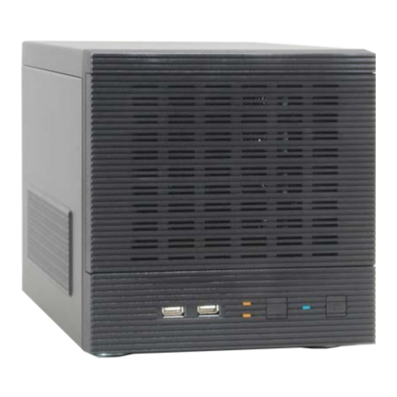
System Overview Front View Rear View... -
Page 6: Led Definition
LED Definition... -
Page 7: Installation
Installation HDD Installation Release the HDD tray by pulling the lock to the right. Pull the HDD tray out of the case. - Page 8 Place the HDD in the tray and Put the HDD tray back to the case. Secure it with the screws at the bottom of the tray...
- Page 9 Push the tray door back to the case to secure it.
-
Page 10: Connect To The Nvr
Connect to the NVR There are various ways you can connect to the NVR and below are the suggested methods for different network setup: The NVR is placed in a network with a DHCP server: Connect to • the NVR by using “Device Search” Utility The NVR is placed in a network without DHCP server (or you are •... - Page 11 To begin, launch the “Deivce Search” utility from the CD and proceed with the installation:...
- Page 12 Once the installation is complete, check the “Launch the Search AP” option and click “Finish”. The search should start automatically and its status should be dis- played.
- Page 13 The NVR should be located and its IP address should be displayed. Double-click on an NVR and the search program should automati- cally access the NVR’s web administration page from your default browser.
- Page 14 You should be prompted for the the NVR’s username and password. Enter its default username “admin” and password “admin” and then click”OK” to enter the system...
-
Page 15: Access The Nvr With Its Default Ip Address
Access the NVR with its default IP address The NVR comes with a pre-configured static IP “192.168.101.50”. However, it is only used when there is no DHCP server presented in the network. The NVR will turn on its DHCP server function and act as the DHCP server in the network. -
Page 16: Set Up Password
Again, you should be prompted for the username and password. Enter its default username “admin” and password “admin” and then click”OK” to enter the system Set up Password... - Page 17 The default login username and password is admin/admin. To change the password of the admin account, go to “Setup” --> “System Con- figurations” --> “User Account”, click on the “admin” account in the account list then press the “edit” button to change its password. Finally, click “Apply”...
-
Page 18: Camera Installation
Camera Installation Add a Camera -- Automatic Search Click the “Search” button to perform the camera search. You should be prompted to install Active Control component in order for the search to function properly. Go ahead and click “Install”... - Page 19 After that, the search should begin and its status should be displayed: Found cameras should be listed and simply select a camera from the list and press “Configure”...
-
Page 20: Add A Camera Manually
Its corresponding information should be displayed in the “Camera Information” section. Enter its username and password and select the channel ID and name the camera. Click on “Detect” to establish connection between the recorder and the camera. If connection establishes successfully, camera’s detailed information should be polled and displayed as below. - Page 21 Simply follow the instruction described above but instead of using the “Search” function, enter the camera’s IP address and credential in the “Camera Information” manually...
-
Page 22: Live View
Live View The “Live View” page provides the following functions: • Retrieve camera’s video stream • Retrieve camera’s status • Perform Live Sequence Viewing • PTZ Control • Perform PTZ Preset Sequence viewing • Perform manual recording • Take snapshot •... -
Page 23: Retrieve Camera's Video Stream
Retrieve camera’s video stream The camera list is expanded and displayed on the Live View page: • Click “All” to display videos of all 32 channels • Click “1-16” or "17-32" to display videos of in 16-video view • Click on a “Group” (ex. Group 1) to display videos from cameras under that group in quad view •... -
Page 24: Perform Sequence Viewing
Red: Performing event recording Green: Recording (manual/continuous/schedule) White: This channel is not configured with any camera Perform Sequence Viewing Sequence view is a function that allows you to view multiple video streams from certain cameras in sequence automatically without having to select them one by one. To perform sequence view, select “SEQ View”... - Page 25 Next, select one or more camera(s) or camera group(s) for sequence viewing: Select "1-16" and "17-32" to start sequence viewing in 16-video view Select "Group(x)" to start sequence viewing in quad view Select "cameras" to start sequence viewing in single video view...
-
Page 26: Ptz Control
Then, select dwell interval from the drop-down menu and click "Start" to begin. PTZ Control PTZ control provides functions to pan, tilt, zoom a PTZ camera as well as the ability to adjust camera focus and iris. - Page 27 Only PTZ capable cameras will be listed in the drop-down menu...
-
Page 28: Perform Ptz Preset Viewing
The bar highlighted above controls the moving angle. Larger number means bigger movement angle. Perform PTZ Preset Viewing There are three functions provided in the “Preset” section: • Perform preset point viewing of a particular camera • Auto pan a particular camera •... -
Page 29: Preset Point Viewing
Preset Point Viewing Start by selecting a PTZ camera from the drop-down list Its available PTZ preset points will be listed in the drop-down list shown below. Click "Go to" to move to the selected position. -
Page 30: Auto Pan Viewing
Auto Pan Viewing Use the Auto Pan control buttons to pan right, left and stop auto pan * Certain cameras do not support bi-directional pan movements. Use the “Autopan” button for such cameras Preset Point Sequence Viewing This function allows you to view multiple preset points from a video of a camera without having to select them one by one. -
Page 31: Live Video Controls
the recorder will begin to display videos from those preset points in sequence automatically until you click “Stop” Live Video Controls Users can perform certain functions to a live view video. They can be accessed by right-clicking on a video. Display ratio and full screen By default, the videos are set to fill the whole video window, to display its original size or ratio, use the button in the upper-right hand corner. -
Page 32: Take A Snapshot Of A Live Video
Take a snapshot of a live video To take a snapshot of a live video, right-click on the video and select "Take Snapshot". - Page 33 An additional window containing the captured image should be displayed. Right-click anywhere on the image and select "Save Picture As..." to save the image.
- Page 34 A dialog should be displayed that allows you to choose a directory/folder of where the snapshot will be saved to.
-
Page 35: Perform Digital Ptz
Perform Digital PTZ To perform digital PTZ on a particual channel, right-click anywhere on its video and select "Digital PTZ". - Page 36 Next, hold the mouse left button and draw a square on the video to specify the zoom in area...
- Page 37 Once the image is digitally zoomed in, use the mouse scroll button to further zoom on or zoom out the image. Hold and left-click on the image and move the mouse to move the zoomed in video.
-
Page 38: Change Web Ui Display Language
Change Web UI Display Language You can change the web UI display language from the current login username link located at the upper-right hand corner. Click on the link opens up a new window which displays detail infor- mation about the user as well as a drop-down menu which lets you change the displyay language. -
Page 39: Live View Through Iphone Safari Browser
Live View through iPhone Safari Browser You can use iPhone and perform single channel live view to the NVR by using its Safari browser. To be able to view the live video through the Safari browser, make sure “javascript” is on under “Settings” >> “Safari”... - Page 40 Type in the IP address of the NVR in the address bar...
- Page 41 You should be prompted to enter the username and password to access the NVR...
- Page 42 Upon successful login, you should see the live view video of the first channel...
- Page 43 Click on the “Channel” drop-down menu to select other cameras...
-
Page 44: Live View Through Blackberry Phones
If a PTZ camera is selected, the corresponding control buttons will display (control PT only) * Please note that this function is camera dependent and is not available to all cameras. Certain cameras do not allow adjusting image size and the selection “Auto” will be used. Live View through Blackberry Phones You can use Blackberry and perform single channel live view to the NVR by using its Safari browser. - Page 45 Enable the “Support Javascript” option and click the menu button and click “Save Options” Go to “General Properties...
- Page 46 Make sure two options illustrated above are enabled Press the menu button and click the “Save Options” to save settings...
- Page 47 Press the button highlighted above to go back to the browser...
- Page 48 Type in the IP address of the NVR in the address bar...
- Page 49 You should be prompted to enter its username and password for access...
-
Page 50: Playback
Playback Playback is a function that allows you to play one or more videos that were previously recorded by a chosen recording method or due to an event trigger. The NVR offers synchronized playback from up to 4 channels and various types of search methods are provided to help you find the footage you need quickly. -
Page 51: Search By Time Chart
Search by time chart 1. Start by selecting which channel(s) you would like to perform a search on. 2. Select “Search by time chart” from the “Search Method” drop-down list and click “Go” to start the search * Selected channels will be marked in red... - Page 52 Results will then be displayed in a new dialog with a “Month/Channel” table and boxes marked in dark gray represent videos found in those dates. (* Videos from other cameras that are recorded on the same date will also be displayed )
-
Page 53: Search By Event
Clicking on a cell box marked with gray will take you to the "day" view of the selected month. Repeating the same step will eventually take you to the "second" view (5sec per cell box). Right-click anywhere or the "Back" button on the table will take you back to the previous view. Click on the play button at anytime will start playing videos from the beginning of the current time view (ex. - Page 54 Start by selecting which channel(s) you would like to perform a search Select “Search by event” from the “Search Method” drop-down list and click “Go” to start the search...
- Page 55 Results will then be listed like what is shown below (displays the oldest record top down). Click on a particular result to start the playback. (* You can cilck “Next Search” to display the next 15 results.) You may also specify a new start time to search and display results from then on.
-
Page 56: Play By Specific Time
Play by specific time If you know when a recording was taken place, you may choose the “Play by start time” from the “Search Method” drop-down list Then you will be prompted to enter a specific time and date for the recorded video. -
Page 57: Search By Event (Most Recent)
Search by event (Most Recent) This function quickly displays the most recent event recordings from the selected channels, displaying the most recent result top down. - Page 58 You may click “Update” to update the list to display the most recent results.
-
Page 59: Certain Functions You Can Perform To The Playback Video
Certain functions you can perform to the playback video You can do the followings by right-clicking on the playback video: 1. Play Audio 2. Snapshot 3. Export as AVI file 4. Digital PTZ... -
Page 60: Export Playback Videos To Avi Files
Export Playback Videos to AVI Files User can export the recorded playback videos stored on the NVR to a local computer and save them in AVI file format. The files can then be played on the PC by a 3rd party media player such as VLC player or Windows Media player. - Page 61 A new dialog will pop up and allows you to speficy the time frame (or length) of the video you wish to export...
- Page 62 Specify the Start time/End time (or export length) and click "Start" to begin exporting. You will be notified once the process is completed successfully...
-
Page 63: Play Exported Playback Videos With Nvr Media Player
The exported AVI file will be saved under the C partition (or the partition where Windows is installed) * ffdshow is required in order to play the exported AVI file with Win- dows Media Player. You can get it at “http://sourceforge.net/projects/ffd- show-tryout/”... - Page 64 You can also use the NVR Media Player to play the exported AVI files. This can save you the trouble of installing third-party media player or codecs when playing the exported AVI videos. The NVR Media Player will be automatically installed after the CMS software is installed.
- Page 65 Locate the exported AVI file, and click “open”. (normally under “C:\ExportFolder)”...
-
Page 66: Open Event Snapshot Images With Nvr Media Player
The video will then start playing Open Event Snapshot images with NVR Media Player The NVR sends snapshots that are taken when an event occurs to a destined FTP server or mail recepient. These type of snapshot images... -
Page 67: Nvr Setup -- System Configurations
are saved in a proprietary image file format, h4i or p4i, and can only be opened by the NVR media player. To do so, Select “Open” from the top menu then select “Image File”. A new dialog should be displayed which lets you locate the image file. NVR Setup -- System Configurations Network Setup The “System Configurations”... - Page 68 correctly based on your network configurations so that the recorder can be administered through the local area network and cameras can be connected from it. By default, the recorder is set to obtain IP address from DHCP server, it should be sufficient in most network environments, and most likely you should not need to alter anything in this page.
-
Page 69: Ddns Service
2. Enter the IP address, subnet mask, default gateway address and DNS server address for the recorder 3. Enable “DHCP Server” under “DHCP Server” if you wish to use the recorder as a DHCP server, or leave it disabled if there is already a DHCP server in the network 4. - Page 70 *Please make sure a valid DNS server has been configured under the “Network Setting” page in order for this function to work properly. *The NVR currently only works with free DDNS service provided by “DynDNS”. For more information, please go to www.dyndns.com *If the NVR is placed behind a router or Internet gateway, please make sure port forwarding for port 80 is configured on the router or the gat- way in order for the DDNS function to properly register with...
- Page 71 In order to properly configure the DDNS service function, please register a free DDNS domain name and account from DynDNS first. Go http://dyn.com/dns/dyndns-free/ from the browser to do so.
- Page 72 Fill in the necessary fields as illustrated above The page will check whether the hostname you entered has been used by another user or not as soon as you click the “Add to Cart” button. If...
- Page 73 you see below message, simply enter a different and click “Add to Cart” again Once you get to the next page, fill in the necessary fields as illustrated above...
- Page 74 Go back to the NVR’s DDNS service configuration page under “Setup” >> “System Configuration” >> “DDNS Service”. Fill in the domain name you picked during the registration in the “Domain Name” field and the username/password you created in the “User ID” and “Password” field and click “Apply” to finish...
- Page 75 You can click the “Check DDNS Status” button to check the DynDNS service status. If you are getting a “Disconnected” message, it means that DDNS service server is down or the NVR is not connected to the Internet. If everything is ok normally, you should be prompted with a success message...
-
Page 76: Time And Date
Time and Date Set the time and date by selecting the time zone according to your location. It is imperative that you set the recorder’s time correctly to avoid the following errors: • Incorrect display time for playback videos • Inconsistent display time of event logs and when they actually occur After selecting the time zone, choose an option below to set the recorder time •... -
Page 77: User Account
User Account The recorder can be accessed by multiple users simultaneously. You can add, remove, and edit users by using options provided in this page to keep user information organized. Each recorder comes with a built- in “admin” account with password “admin”. It’s highly recommended to change the password upon your initial login. -
Page 78: Add A New User
Add a new user • Enter a username and password in “User Account Information”. All other fields are optional for your own reference. • Select a group from the “Group” drop-down menu to assign the new user to a particular group • Enter a short description for the account if you wish •... -
Page 79: Change The Password Of The "Admin" Account
Change the password of the “admin” account 1. Click and highlight the “admin” account in the account list and click “Edit” 2. Its information should be displayed in “User Account Information” 3. Enter a new password in the “Password” field and enter it again in “Confirm Password”... -
Page 80: Group Privilege
Group Privilege Group Privilege is where you can create multiple customized access policies for situations if you need the recorder to be accessed by us- ers other than the administrator. You can do so by creating a group, and then remove access privileges for certain configuration pages or cameras. - Page 81 You can change the group name by clicking the “Change Group Name” button. A text box will be displayed for you to enter the new group. Choose what type of privilege you would like this group to have from the “Privilege Type” drop-down menu.
- Page 82 Its access privilege will then be displayed. You can alter its settings by allowing or denying access to other cameras using the checkboxes instead of accepting the defaults...
-
Page 83: Disk Setup
Disk Setup Once you install a hard disk to the recorder, you would need to initialize it so that it can be ready for recording. You can obtain basic information about the disk you installed in this page. To initialize it, simply click the “Format” button. *This page will list the Internal disks (or RAID volumes), and the E- SATA disk only. - Page 84 The internal HDDs can be used for RAID. To do so, go to "RAID Volume" in Disk Setup and choose the availabe disk action. The "Disk Actions" drop-down menu displays available actions based on how many HDDs are installed in the NVR. For detail, please refer to the table above.
- Page 85 Select a disk action and click "Apply" to proceed. A warning dialog will be displayed as creating RAID volume will erase all existing data on the HDDs. Click "OK" to continue.
- Page 86 Please wait for a few moment while the NVR is creating the RAID volume. You will be prompted once the action is completed successfully.
- Page 87 Once the RAID volume is created, it will be listed in the "RAID volume list with the status of "Offline"...
- Page 88 Go back to the "Hard Disk List" page and the RAID volume should be in the list. Click "Format" to bring the RAID volume online. The status will be displayed just as if you were formating any internal HDDs...
-
Page 89: Deleting Raid
Deleting RAID Once a RAID volume is created, it can be deleted at anytime by choosing the "Delete RAID" action in the RAID volume page. All existing data will be removed after the RAID volume is deleted. All internal disks that were originally used for RAID volume will have to be formatted again after the RAID volume is deleted. - Page 90 * Once a RAID volume is deleted, all internal disks within that RAID should become offline and need to be formatted again before they can be used individually. * All internal disks (or RAID volumes) need to be formatted before they can be used.
-
Page 91: Nvr Setup -- Channel Configurations
NVR Setup -- Channel Configurations Add a camera The NVR provides two options for adding a new camera. Users have the option to let the recorder automatically find the cameras or it is possible to enter camera’s information and add it manually. Automatic Search... - Page 92 Click the “Search” button to perform the camera search. You should be prompted to install Active Control component the first time you visit the page in order for the search to function properly. Go ahead and click “Install” Once you have the ActiveX component installed, the search status should be displayed after clicking "Search"...
- Page 93 Its corresponding information should be displayed in the “Camera Information” section. Enter its username and password and select the channel ID and name the camera. Click on “Detect” to establish connection between the recorder and the camera. If connection establishes successfully, camera’s detailed information should be polled and displayed as below.
- Page 94 Adjust its video format, frame rate, resolution or bitrate...etc if you wish. You can also click on the “Preview” to preview the live video of the camera. Click “Add” to finish adding the camera *If cameras are marked with "*" in the search result, it means those cameras are already configured and connected to the NVR.
- Page 95 Once the camera's settings are polled and displayed, you can also enable "continuous" recording and adjust its recording quality settings before adding the camera. Some cameras are capable of multiple streaming profiles, in which different video codecs are used for different purposes. You will be able to use different video format for continuous recording if it's a multi-stream capable camera.
- Page 96 There are two types of fps settings here, one is the fps that NVR sets back to the camera, and this is the fps NVR will be receiving from the camera. The other is recording fps which will be limited by the live fps. (ex.
-
Page 97: Add A Camera Manually
Add a camera manually Simply follow the instruction described above but instead of using the “Search” function, enter the camera’s IP address and cre- dential in the “Camera Information” manually. -
Page 98: Osd Settings
OSD Settings The OSD (On Screen Display) allows users to add informational text message and embed it onto the video. By default, this function is turned off. To add texts to one or more videos. Select a camera you would like to add text to and choose “Display OSD”... - Page 99 Next, define where the text will be displayed by either entering an X/Y coordinate or use the system pre-defined position from the drop-down menu. Click on the “Preview” button to see the preview of your setting and click “Apply” to save the configuration.
- Page 100 The texts can be further adjusted with changes to different size, color or font so they can be more visible on the video.
-
Page 101: Ptz Setting
PTZ Setting PTZ Preset Settings The recorder supports PTZ cameras and can set multiple preset points or retrieve and manage preset points that are set in the camera. This is helpful if you need to monitor multiple spots in one area from a particular camera. - Page 102 To set up PTZ preset points: 1. Select a camera from the “Camera” drop-down menu and click “Add”. 2. Select a position number for the preset point from the “Position Number” drop-down menu and fill in a name in the “Position Name” field for easier identification.
-
Page 103: Ptz Preset Sequence
Ultimately, you can choose to make this preset point a “Home” point among all other preset points, as well as making the camera to move to this particular point when an event is triggered. * “Move Here when Event Trigger”: In order for this function to work properly, please also complete configuration in “Event Configuration”... - Page 104 To configure preset sequence for a camera, 1. Select a channel from the “Channel” drop-down menu. The available preset points should be listed in “Camera Presets” section. 2. Pick the ones you like for sequence viewing and press the “->” button to move them to the “Preset Sequence”...
-
Page 105: E-Map Setting
E-Map Setting Local E-Map Setting E-Map monitor is a function that alerts users whenever there is an event triggered (e.g. motion detected) from a camera with a geographical perspective. With this function, users can quickly identify which camera has detected an unusual event and where this event is happening. - Page 106 To replace the map, click “Browse” button to locate the new map image file from the local PC and then click “Upload”. * Only JPG, PNG, and GIF file formats are supported with file size under 100KB.
- Page 107 Then click and drag the camera icon to move the camera to define its location. Access the E-Map Monitor page from the upper-right hand corner menu. When the NVR receives an event triggered from any of the cameras, their videos will be displayed on the E-Map and you can double-click on the video to enlarge it.
-
Page 108: Google Map Setting
Google Map Setting The Google Map monitor is a similar function to the aforementioned E- Map monitor. It is useful if you are managing multiple cameras from different locations. To configure locations of each camera, first determine the location you’d like to place the camera to on the map. You can do so by:... - Page 109 1. Zoom in to a smaller area by using the zoom control bar on the map 2. Zoom in to a smaller area by using the mouse scroll button You can also go to a specific place on the map by entering its address or the name of the place in the “Address or places of interest”...
-
Page 110: Nvr Setup -- Event Configurations
NVR Setup -- Event Configurations Event Configuration The “Event Configurations” section allows users to define conditions that constitute an event, its corresponding trigger action and when it will be triggered. Such setting can reduce the management overhead and notify the administrator only when it’s necessary. General Settings The general settings section can help you quickly configure when an event is triggered, how often events are triggered and the... - Page 111 and “End Time” fields that you would like the event trigger function to be enabled. How often an event is triggered • Set a time interval under “Event Trigger Interval” to define how often events are triggered Trigger action Now that you have the event trigger duration and interval defined, choose what action to be taken during an event trigger: •...
-
Page 112: I/O Settings
I/O Settings This function allows users to manage camera’s digital input and output ports right from the recorder. You can setup the recorder to receive triggers from a particular camera’s input port and trigger a device, such as an alarm that is connected to the recorder or camera’s output port. - Page 113 *Some cameras only allow one trigger source be configured at a time, e.g.: if the camera has the motion detection function turned on, its digital input will be disabled and vice versa. Under such circumstance, if you set to use camera’s digital input port as the event trigger source, you will not be able to select motion detection as the trigger source for this camera under “Event Configurations”...
-
Page 114: Event Servers
Event Servers Configuring an FTP server Event servers are to be used with event trigger actions. In case of unusual motion detected by the camera or a disk failure, the recorder can send notification with the acceptable format (image/txt) to a destined event server according to the configuration. - Page 115 To add an FTP server, 1. Start by giving a name to the server that you are adding to the recorder 2. Enter the hostname or the IP address of the FTP server 3. Enter the communication port of the FTP server (usually port 21) 4.
-
Page 116: Configuring An Smtp Server
Configuring an SMTP server 1. Enter the hostname or the IP address of the SMTP server 2. Enter the port of the SMTP server 3. Specify the sender’s name in the “Sender’s name” field 4. Enter the sender’s e-mail address 5. -
Page 117: Event Triggers
Event Triggers We have finished defining how an event will be triggered and which servers will be receiving notifications in the previous two sections, now we can finish up the event configuration by setting: • which channels will have event trigger function enabled •What is considered to be an event •Where the warnings will be sent to and how they will be sent Use the checkbox to enable event trigger on the desired channels. - Page 118 *Once motion detection is enabled in this page, please configure the motion area and enable motion detection in the corresponding channels (cameras) from camera's own web UI. The NVR only detects the first motion area set in the camera. The NVR recognizes the first motion area by its ID number set in the camera.
-
Page 119: Nvr Setup -- Recording Configurations
NVR Setup -- Recording Configurations General Settings The “recording configurations” gives users the overall control of how and when a recording is performed and the quality of different types of recordings performed on each channels. It can help the recorder to operate with sufficient system resource by performing recording only when it’s necessary with adjustable recording frame rate. - Page 120 The “recording buffer” allows user to define “pre-alarm” and “post- alarm” time for event recordings. The “pre-alarm” time sets the NVR to record in advance when an event is triggered. The “post-alarm” time sets the NVR to continue recording for a period of time after an event trigger is finished.
- Page 121 only. Use the drop-down menu and select one of the pre-defined frame rates for a particular recording type You are able to use the same video format for recordings or you can choose other formats for different recording purposes if it's a multi- stream capable cameras.
- Page 122 Users can also set to keep a previous number of days of recording data by enabling the option below. This is quite often used in applica- tion such as banking which certain countries requires to always keep a minimum previous number of days of recording data. * If this option is enabled, once the hard drive is full, the recycle function will then start but it will ensure that the number of days of recording data defined here will stay in hard drive instead of wiping...
- Page 123 The section at the bottom of the page allows you to disable audio recording (record video only) of particular channels.
-
Page 124: Schedule Recording
Schedule Recording You can define the time range of the schedule recording for all channels in this page. To configure a schedule recording Use the “Channel” drop-down menu and select a camera first. - Page 125 You can use the schedule table to set the time range. Click the cell boxes then move horizontally lets you set what hours to perform recording during a day. Click and move vertically lets you set what days to perform recording at a specific time. * Each cell box represents 15 minutes of time.
-
Page 126: Nvr Setup -- System Options
Select the “Copy to” option if you would like to set the same re- cording schedule to another camera. NVR Setup -- System Options Device Information System Options gives users a glance of the overall system status and allows users to perform maintenance tasks such as upgrading firm- ware, restore/backup device settings or reboot device ..etc. -
Page 127: Logs And Reports
Logs and Reports “Logs and Reports” keeps a record of what’s been happening to the device and provides basic information for troubleshooting. -
Page 128: Maintenance
Maintenance “Maintenance” provides functions for users to: • Reboot the NVR when necessary • Reboot cameras directly from the NVR • Perform Firmware Upgrade • Backup the NVR’s settings to a local hard drive • Restore the NVR’s settings from a previously saved configuration file •... -
Page 129: Reboot The Nvr At A Specific Time Automatically
Reboot the NVR at a specific time automatically You can configure the NVR to restart automatically by using the options given in the web UI. You can set the NVR to restart at a particular hour of a specific day during a week or a month. Firmware Upgrade The firmware can be upgraded through web UI or USB. - Page 130 Login into NVR’s web management UI. Go to "Setup" page and go to "System Options"->"Maintenance" On "Upgrade NVR's Firmware" section, click "Browse" and select new firmware file A new dialog should display and let you choose the location of the firmware file.
- Page 131 When done, click “Upgrade”. Follow the on screen instruction and wait for the process to finish (After upgrade, the system will reboot automatically, it’s part of the process)
-
Page 132: Upgrade Through Usb Thumb Drive
Upgrade through USB thumb drive 1. Prepare a USB flash disk and format with FAT or FAT32 format 2. Place the firmware in the USB flash disk and make sure it’s placed at the top-level directory. Please do not place the file in a folder. (make sure to change the firmware file name to “firmware”... - Page 133 The process should be displayed and you should be prompted back to the “Live View” page after it is complete.
-
Page 134: Disk Status
Disk Status “Disk Status” gives you a more detailed information of the hard drive that is currently installed in the NVR. -
Page 135: Usb Backup
USB Backup It’s a function that allows users to backup the recording data in its database file format (not AVI) to the externally connected USB hard disk. You can check the “Disk Status” page under “System Options” to see if the USB disk has been detected by the NVR. - Page 136 Once it’s detected, go back to the “USB Backup” page and it should be available for further configuration The USB hard disk(s) will be listed in the drop-down menu displaying the remaining disk space. Make your selection from the drop-down menu if you have more than one disks connected to the NVR.
-
Page 137: Things To Pay Attention To The Usb Backup Function
Next, select channels which you would like to backup the recording data from. Maximum 4 channels can be selected at once Configure the start and end time of the recording data you would like to backup and click the “Backup” button to begin. Things to pay attention to the USB Backup function Limitation: •... -
Page 138: Play The Backup File With The Nvr Media Player
Process: • Progress will be displayed on the UI • If the backup process gets interrupted, which the process stops at a point of time that is before the “END Time” user defined, such time will be displayed on the UI •... - Page 139 Click “Browse...” to select the file from the USB disk. A new dialog should be prompted for you to select the file location.
- Page 140 When done, click “Check” to validate the file. Once the file has been successfully verified, you should be prompted with the message shown below.
- Page 141 Select the time zone according to your current location. Finally, click “OK” to begin playing. The player should now play the backed up file.
- Page 142 About LevelOne LevelOne was established in 1998 in Dortmund, Germany by Digital Data Communications GmbH. By providing quality networking products and solutions, we've grown steadily throughout the years with Branch Offices in 18 countries around the world. The Internet has become a deeply integral part of both business and home life.
Need help?
Do you have a question about the NVR-0432 and is the answer not in the manual?
Questions and answers