Powermatic 66 Instruction Manual & Parts List
10" tilting arbor saw
Hide thumbs
Also See for 66:
- Operating instructions and parts manual (40 pages) ,
- Instruction manual & parts list (28 pages) ,
- Maintenance instructions and parts list (25 pages)

Related Manuals for Powermatic 66


Summary of Contents for Powermatic 66
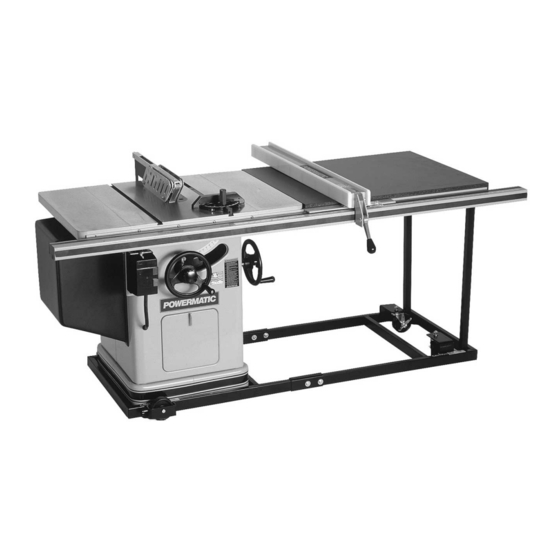
- Page 1 10" TILTING ARBOR SAW Model 66 Instruction Manual & Parts List M-0460231 shown with optional extension table & legs, mobile base, and motor cover (800) 274-6848 www.powermatic.com...
-
Page 2: More Information
This manual has been prepared for the owner and operators of a Powermatic Model 66 Tilting Arbor Table Saw. Its purpose, aside from machine operation, is to promote safety through the use of accepted correct operating and maintenance procedures. Completely read the safety and maintenance instructions before operating or servicing the machine. -
Page 3: Table Of Contents
TABLE OF CONTENTS Safety Rules ............................4-5 Decal Instruction ............................. 6 Specifications ............................7 Receiving the Saw ..........................8 Installation and Assembly ........................8 Mounting extension wings ........................ 9 Installing blade ..........................9 Mounting rails & Accu-Fence ......................10 Optional wood extension table ....................... 10 Splitter and guard assembly. -
Page 4: Safety Rules
Make certain the work area is well lighted and that a proper exhaust system is used to minimize dust. Powermatic recommends the use of anti-skid floor strips on the floor area where the operator normally stands and that each machine’s work area be marked off. Provide adequate work space around the machine. - Page 5 Misuse. Do not use this Powermatic table saw for other than its intended use. If used for other purposes, Powermatic disclaims any real or implied warranty and holds itself harmless for any injury or damage which may result from that use.
-
Page 6: Decal Instruction
SAFETY Familiarize yourself with the location of these safety decals on your table saw. 3408257... -
Page 7: Specifications
Shipping Weight with Motor, Fence & Rails ..................614 lbs. NOTE: The above specifications were current at the time this manual was published, but because of our policy of continuous improvement, Powermatic reserves the right to change specifications without notice and without incurring obligations. -
Page 8: Receiving The Saw
RECEIVING THE SAW Hex Head Screw 3/8-16 x 1 Qty. 6 Open shipping container and all separate cartons con- taining rails and accessories. Report any damage immediately to your distributor. Read the instruction manual thoroughly for assembly, alignment, mainte- nance and safety instructions. Lock Washer Box contents: Qty. -
Page 9: Mounting Extension Wings
MOUNTING EXTENSION WINGS Mount the cast iron extension wings using six 3/8-16 x 1 hex head screws and six 3/8 lock wash- ers. See Figure 2. Have an assistant hold the wing up to the table, and insert the screws and washers. Finger tighten only. -
Page 10: Mounting Rails & Accu-Fence
MOUNTING RAILS & ACCU-FENCE With the extension wings properly aligned, the rail and fence assembly can now be mounted to the saw. Consult the separate Accu-Fence manual for instruc- tions. OPTIONAL WOOD EXTENSION TABLE For instructions on mounting the accessory wood ex- tension table, or router table, consult your Accu-Fence manual. -
Page 11: Electrical Connections
ELECTRICAL CONNECTIONS WARNING: All electrical connections should be done by a qualified electrician. Failure to comply may result in serious injury. The machine must be properly grounded. Consult the electrical schematics on pages 33-36 for proper wiring of the table saw. ADJUSTMENTS FIGURE 10 BLADE RAISING &... -
Page 12: Tilt Stop Adjustment
TILT STOP ADJUSTMENT Using a combination square, check the 90 degree (0) and 45 degree stops as shown in Figure 14. Ad- just stop positions if required, using the stop screws as shown. Check the accuracy of the pointer at 90 degrees (0) and readjust if required. -
Page 13: Splitter Alignment
SPLITTER ALIGNMENT One of the most critical adjustments to help avoid kickback is the splitter adjustment. It should be checked and readjusted, if required, after each blade change. Lift the mitre gauge bar slightly out of its slot. Place a combination square against the side of the raised up miter gauge bar and slide the scale against the top of the blade tooth and against the splitter as shown in Figure 17. -
Page 14: Tilting Mechanism Adjustment
If the saw arm has been relocated, the table may have to be realigned so as to provide clearance between the saw blade and table insert slot. The splitter will also have to be realigned. NOTE: The saw arm setscrew must be tight to avoid the possibility of movement which could cause the blade to hit the insert. -
Page 15: Operating Instructions
OPERATING INSTRUCTIONS FOR TABLE SAWS Familiarize yourself with the location and op- eration of all controls and adjustments and the use of accessories such as the mitre gauge and rip fence. Serious injury can result from kickbacks which occur when a work piece binds on the saw blade or binds between the saw blade and rip fence or other fixed object. -
Page 16: Rip Sawing
Dull, badly set, improper, or improperly filed cut- ting tools and cutting tools with gum or resin adher- ing to them can cause accidents. Never use a cracked saw blade. The use of a sharp, well main- tained, and correct cutting tool for the operation will help to avoid injuries. - Page 17 NOTE: A caution decal is installed on the guard and splitter assembly warning of the hazard of misalign- ment. The rip fence should be set for the width of the cut by using the scale on the front rail, or by measur- ing the distance between the blade and fence.
-
Page 18: Resawing
RESAWING Resawing is a ripping operation in which thick boards are cut into thinner ones. Narrow boards up to 3" can be resawed in one pass. Wider boards up to 6" must be resawed in two passes. In resawing wider boards, adjust the blade height so as to overlap the two cuts by 1/2"... -
Page 19: Bevel & Mitre Operations
Stop rods can be used in the holes provided in the mitre gauge for repetitive work of equal length. Do not use a stop rod on the free end of a workpiece. It should be used on the side of the mitre gauge op- posite the saw blade. -
Page 20: Safety Devices
The guard, splitter, and anti-kickback pawls supplied with the saw should be used for all cutting opera- tions where they can be used. When performing op- erations where the guard can not be used, as in some dadoing operations, alternative safety precautions should be taken. - Page 21 FIGURE 37 FIGURE 38...
-
Page 22: Trouble-Shooting
Trouble-Shooting for Model 66 Table Saw PROBLEM POSSIBLE CAUSE SOLUTION [with page #] Excessive Vibration. 1. Tilt or raising clamp knobs not tightened. 1. Tighten knobs. 2. Blade out of balance. 2. Change blade. [9] 3. Bad motor. 3. Replace motor. -
Page 23: Optional Accessories
2195042 Accu-Fence and rail system for ripping 50" to right and 12" to left of saw blade. 2195047 Accu-Fence - fence assembly only - no rails for Model 66. 2195049 Accu-Fence and rail system for Model 66 w/sliding table. 2195063 Accu-Fence and rail system for ripping 30"... -
Page 24: Trunnion Assembly
PARTS LIST: Trunnion Assembly (Model 66) Part No. Description Quantity 2025002 Saw Raising Bearing Arm Assembly (Items 1 -12, 16, 52 & 68) ......1 2024018 Complete Arbor Assembly (Items 1 thru 5, 36 & 38) ..........1 3700123 Shaft ........................1 6670015 Retainer Ring ...................... - Page 25 PARTS LIST: Trunnion Assembly (Model 66) Part No. Description Quantity 2690057 Splitter Adjustment Screw Assembly (Items 60 & 61) ..........1 6716195 Socket Set Screw, 3/8-16 x 1-1/2 ................1 3690232 Adjustment Screw, 3/4-16 x 1-1/2 ................1 6716079 Square Head Screw, 3/8-16 x 1 ................1 6716039 Hex Head Screw, 3/8-16 x 1-1/4 ................
-
Page 26: Trunnion Assembly
Trunnion Assembly (Model 66) -
Page 27: Mitre Gauge
PARTS LIST: Mitre Gauge (model 66) Part No. Description Quantity 2471015 Mitre Gauge Assembly (Items 1 Thru 14) .............. 1 3044053 Mitre Gauge Bar ....................1 3230038 Mitre Gauge ......................1 3604035 Mitre Gauge Pointer ....................1 3585221 Stop Pin ......................... 1 3841202 Mitre Gauge Bar Washer .................. -
Page 28: Splitter & Guard Assembly
PARTS LIST: Splitter & Guard Assembly (Model 66) Part No. Description Quantity 2787008 Splitter Rear Support Assembly (Items 1 thru 7) ............ 1 6715034 Hex Head Cap Screw, 5/16-18 x 1-1/4 ..............1 6861200 Lock Washer, 5/16....................1 3776050 Splitter Rear Support ..................... 1 6572007 Spanner Lock Nut, 3/4-16 .................. -
Page 29: Splitter & Guard Assembly
Splitter & Guard Assembly (Model 66) - Page 30 PARTS LIST: Stand Assembly (Model 66) Part No. Description Quantity 6716031 Hex Head Screw, 3/8-16 x 1 .................. 9 6861300 Lock Washer, 3/8 ....................9 3186008 Standard Extension, 8" ..................2 2328002 Dado Insert Assembly (Items 4 & 5) ..............1 6714081 (Pkg of 5) Socket Set Screw (Nylok), 1/4-20 x 3/8 ..........
-
Page 31: Stand Assembly
Stand Assembly (Model 66) -
Page 32: Table Extension & Legs (Optional Accessory)
PARTS LIST: Table Extension & Legs (optional accessory - Model 66) Part No. Description Quantity 2389003 Extension Kit (Items 1 thru 10) ................1 2423001 Extension Table Support Leg Assembly (Items 1 thru 8) ........1 2423006 Inner Extension Leg Assembly ................1 3186009 Outer Extension Leg .................... -
Page 37: Preventive Maintenance Checklist
Preventive Maintenance Checklist Model 66 Table Saw These should be performed monthly, or more frequently if needed: Inspect entire machine for loose bolts, nuts, screws. Tighten and replace as necessary. Thoroughly clean trunnion area, removing sawdust and chips with soft bristle brush. - Page 39 Locating the stock number of the part(s) required from your parts manual will also expedite your order. Phone No.: (800) 274-6848 Fax No. (800) 274-6840 If you are calling from Canada, please call 800-238-4746 E-mail: powermatic@wmhtoolgroup.com Website: www.powermatic.com...
- Page 40 12/02 WMH Tool Group 427 Sanford Rd. LaVergne, TN 37086 Phone: (800) 274-6848 Fax: (800) 274-6840 E-mail: powermatic@wmhtoolgroup.com Website: www.powermatic.com POWERMATIC ALL RIGHTS RESERVED...
Need help?
Do you have a question about the 66 and is the answer not in the manual?
Questions and answers