Powermatic 64A Instruction Manual
10" contractor's saw
Hide thumbs
Also See for 64A:
- Operating instructions and parts manual (36 pages) ,
- Operating instructions and parts manual (16 pages)

Related Manuals for Powermatic 64A


Summary of Contents for Powermatic 64A
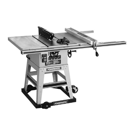
- Page 1 10" CONTRACTOR'S SAW Model 64A Instruction Manual & Parts List M-0460250 shown on optional mobile base (800) 274-6848 www.powermatic.com...
-
Page 2: More Information
This manual has been prepared for the owner and operators of a Powermatic Model 64A Table Saw. Its purpose, aside from machine operation, is to promote safety through the use of ac- cepted correct operating and maintenance procedures. Completely read the safety and mainte- nance instructions before operating or servicing the machine. -
Page 3: Table Of Contents
TABLE OF CONTENTS Safety Rules ..............................4-5 Safety Decals ............................... 6 Features ................................7 Specifications ............................... 7 Receiving ................................8 Installation & Assembly ............................8 Stand Assembly ............................9 Mounting Saw to Stand ..........................10 Assembling Handwheels and Lock Knobs ..................... 10 Mounting the Motor ............................ -
Page 4: Safety Rules
Make certain the work area is well lighted and that a proper exhaust system is used to minimize dust. Powermatic recommends the use of anti-skid floor strips on the floor area where the operator normally stands and that each machine’s work area be marked off. Provide adequate work space around the machine. - Page 5 Misuse. Do not use this Powermatic table saw for other than its intended use. If used for other purposes, Powermatic disclaims any real or implied warranty and holds itself harmless for any injury or damage which may result from that use.
-
Page 6: Safety Decals
Familiarize yourself with the following safety notices used in this manual: CAUTION: (This means that if precautions are not heeded, it may result in minor or moderate injury and/or possible machine damage) WARNING: (This means that if precautions are not heeded, it could result in serious injury or possibly even death). -
Page 7: Features
Switch .......................Push button with safety key Weight ............................ 310 lbs. NOTE: The above specifications were current at the time this manual was published, but because of our policy of continuous improvement, Powermatic reserves the right to change specifications without notice and without incurring obligations. -
Page 8: Receiving
RECEIVING Remove the saw and accessories from the shipping carton and inspect for damage. Any damage should be reported to your distributor and shipping agent im- mediately. Before proceeding further, read your instruction manual thoroughly to familiarize yourself with proper assem- bly, maintenance and safety procedures. -
Page 9: Stand Assembly
Remove the protective coating from the saw table sur- face with a soft cloth moistened with a good commer- cial solvent. NOTE: Do not use acetone, gasoline, or lacquer thin- ner to remove the protective coating, as it can dam- age plastic parts and painted areas. -
Page 10: Mounting Saw To Stand
MOUNTING SAW TO STAND Tools required 12mm wrench. Tip: Remove all contents from box except saw and one extension wing. Put some soft padding on floor beside box. Fold back carton flaps and gently roll box upside down on to padding. Lift off box, being care- ful not to let extension wing fall. -
Page 11: Mounting The Motor
Attach the elevating and tilting handwheels with lock knobs to the elevating and tilting screws on the machine, as shown in Figure 5. Make sure the slot in both handwheels engages with the roll pins in the el- evating and tilting screws. FIGURE 6 MOUNTING THE MOTOR Tools required... -
Page 12: Mounting Blade Guard & Splitter
Install the motor assembly onto the protruding studs at the back of the saw. See Figure 10. Tighten down setscrews in top of cast motor bracket with hex wrench as shown in Figure 10. Use an assistant or get a support block (a 2 x 4 for example) approximately 21"... -
Page 13: Saw Blade Installation
Loosen top screws (A) on the mounting bracket, and the screw (C) on the inside splitter mounting plate, as shown in Figure 14. The slotted legs of the splitter assembly will slide onto the screws. (You may need to loosen set screws (B), Figure 13, to slide bracket to required position on pin.) TIP: The slotted section of the splitter may be difficult to position over the screw on the mounting plate (C). -
Page 14: Mounting Table Insert
MOUNTING TABLE INSERT Tools required 3mm hex wrench. Place the table insert in the saw blade opening. With a straight edge, check to see if the insert is level with the surface of the table. See Figure 17. If the insert is not level, correct it by using the straight edge and turning the four 1/4-20 x 5/16 set screws in or out until the insert is flush with the table. -
Page 15: Mounting Rails & Accu-Fence
MOUNTING RAILS & ACCU-FENCE With the extension wings properly aligned, the rail and fence assembly can now be mounted to the saw. Consult the separate Accu-Fence manual for instruc- tions. OPTIONAL WOOD EXTENSION TABLE For instructions on mounting the accessory wood ex- tension table, or router table, consult your Accu-Fence manual. -
Page 16: Mitre Gauge Assembly
MITRE GAUGE ASSEMBLY Mount the gauge body to the bar, making sure the pins underneath the body fall in the holes in the bar. See Figure 21. Place the fiber washer on to the threaded rod, and screw on the handle. Slide the mitre gauge into the left hand slot on the saw table. - Page 17 Check with a qualified electrician or service personnel if the grounding instructions are not completely under- stood, or if in doubt as to whether the tool is properly grounded. Use only 3-wire extension cords that have 3-prong grounding plugs and 3-pole receptacles that accept the tool’s plug.
-
Page 18: Adjustments
ADJUSTMENTS CAUTION: Disconnect motor from power source before making any adjustments. BLADE ADJUSTMENT To raise and lower the saw blade, loosen the front lock knob (A) on the elevating handwheel as shown in Figure 24. Turn front handwheel (B) clockwise to raise saw blade and counterclockwise to lower saw blade. -
Page 19: 45 And 90 Degree Positive Stops
45 AND 90 DEGREE POSITIVE STOPS Tools required Adjustable wrench (or pliers) Convenient access to these adjustments will be from the back side of the saw. Disconnect machine from power source. Raise the saw blade to its maximum height. Set the blade at 90 degrees to the table by turn- FIGURE 26 ing the blade tilting handwheel clockwise as far as it will go. -
Page 20: Aligning Splitter To Blade
TO CHECK AND ADJUST THE 90 DEGREE SETTING OF THE MITRE GAUGE, DO THE FOLLOWING: Set the gauge at 90 degrees as shown in Figure Place a metal square against the face of the mi- tre gauge and along one edge of the miter gauge slot and check to see if edge of square fits flush with the mitre gauge. -
Page 21: Maintenance
MAINTENANCE Good saw operation requires periodic preventive main- tenance. Keep the inside of the cabinet and trunnion ar- eas clean. A stiff brush will remove sawdust before it cakes, and pitch or gum is easily removed with a com- mercial solvent. After cleaning the tilting and raising worm, and worm gear segments, and the trunnions, grease these three areas with a good grade non-hardening grease. - Page 22 Using a dull saw blade. Not maintaining alignment of the rip fence. (Fence should angle away from, rather than towards, the saw blade front to back.) NOTE: A caution decal on guard and splitter assem- bly warns against misalignment. Applying feed force in ripping to the cutoff (free) section of the workpiece instead of the section be- tween the saw blade and fence.
-
Page 23: Operating Procedures Ripping
Always keep your hands out of line with the saw blade and never reach past the rotating blade with ei- ther hand to hold down the workpiece. Use the mitre gauge on the left hand side of the saw blade when doing mitre or compound miter cuts to provide more hand clearance and safety. -
Page 24: Resawing
Always push the workpiece completely past the blade at the end of a cut to minimize the possibility of a kickback. In ripping long boards, use a support at the front of the table and a support or “tailman” at the rear. For work shorter than 12"... -
Page 25: Bevel And Mitre Operations
For 90 degree crosscutting, most operators pre- fer to use the left-hand mitre gauge slot. When using it in this position, hold the workpiece against the gauge with the left hand and use the right hand to advance the workpiece. When crosscutting using the right hand slot, the hand positions are reversed. -
Page 26: Electrical: 230 Volt Conversion
230 VOLT CONVERSION WARNING: The conversion from 115V to 230V operation must be done by a qualified electrician. The 64A saw is prewired for 115 volt operation. If 230 LINE volt, single phase operation is desired, the following LINE instructions must be followed: FIGURE 44 Disconnect saw from its power source. -
Page 27: Safety Devices
Filler Piece SAFETY DEVICES (Figure 45) A filler piece is necessary for narrow ripping and per- Feather Board (Figure 44) mits the guard to remain on the machine. It also provides space for the safe use of a push stick. The Feather Board is to be made of straight grain hardwood approximately 1”... -
Page 28: Trouble-Shooting
Trouble-Shooting for Model 64A Contractor's Saw PROBLEM POSSIBLE CAUSE SOLUTION Excessive Vibration. 1. Tilt or raising clamp knobs not tightened. 1. Tighten knobs. 2. Blade out of balance. 2. Change blade. 3. Bad motor. 3. Replace motor. 4. Pulleys loose 4. -
Page 29: Parts Lists & Exploded Views Table Saw, Extension Wings, & Guard
PARTS LIST: Table Saw, Extension Wings, & Guard (64A) Part No. Description Quantity 6290694 Table Insert ......................1 6291342 Rubber spacer ......................2 6290695 Dado Insert ......................1 6290502 Socket Set Screw, 1/4-20 x 5/16 ................8 6290696 Table ........................1 6290697 Cabinet ........................ -
Page 30: Table Saw, Extension Wings, & Guard
PARTS LIST: Table Saw, Extension Wings, & Guard (64A) Part No. Description Quantity 6291377 Switch Assembly (Items 66 thru 70 & 82)..............1 6290629 Power Cord ......................1 64-1 6291373 Power Cord (Junction to Switch) ................1 6290630 Clamp, 7W2 ......................6 6291335 Nut, 3/16-24 ...................... - Page 31 Table Saw, Fence & Wing Table (64A)
-
Page 32: Stand Assembly
PARTS LIST: Stand Assembly (64A) Part No. Description Quantity 6290646 Leg ......................... 4 6290650 Bottom Long Bracket ....................2 6290648 Bottom Short Bracket ..................... 2 6290647 Top Short Bracket ....................2 6290649 Top Long Bracket ....................2 6290645 Dust Cover ......................1 6290664 Pan Head Screw, 3/16-24 x 5/8 ................ -
Page 33: Motor & Trunnion Assembly
PARTS LIST: Motor & Trunnion Assembly (64A) Part No. Description Quantity 6290563 Knob ........................2 6290565 Handle ........................2 6290566 Nut, Hex Hd. 3/8-16 ....................4 6290564 Handwheel ......................2 6290567 Flat Washer, 3/8 ..................... 3 6290678 Pointer ........................1 6290569 Set Screw, 1/4-20 x 1/4 ................... - Page 34 PARTS LIST: Motor & Trunnion Assembly (64A) Part No. Description Quantity 6290631 Electrical Cord (Junction to Motor) ................1 6291384 Carriage Bolt, 5/16-18 x 1-3/4 ................. 2 6291385 Pulley Cover Seat ....................1 6291386 Outer Cover ......................1 6291325 Fiber Washer, 5/16 ....................2 6285540 Wing Nut, 5/16-18 ....................
-
Page 35: Motor & Trunnion Assembly
Motor & Trunnion Assembly (64A) -
Page 36: Casters (Optional)
CASTERS (Optional-64A) PART NO. DESCRIPTION 6290656 Caster (2) -
Page 37: Optional Accessories
OPTIONAL ACCESSORIES 2042339 Mobile base for 30" Accu-Fence without Rout-R-Lift. 2042367 Mobile base for 50" Accu-Fence with or without Rout-R-Lift. 2042370 Mobile base for 30" Accu-Fence with Rout-R-Lift. 2075027 Cabinet and Rout-R-Lift System (17" x 27" table surface). 2195077 Accu-Fence system, 50". 2195075 Accu-Fence assembly only. - Page 39 Locating the stock number of the part(s) required from your parts manual will also expedite your order. Phone: (800) 274-6848 Fax: (800) 274-6840 If you are calling from Canada, please call 800-238-4746 E-mail: powermatic@wmhtoolgroup.com Website: www.powermatic.com...
- Page 40 03/03 WMH Tool Group 427 Sanford Road LaVergne, TN 37086 Phone: (800) 274-6848 Fax: (800) 274-6840 E-mail: powermatic@wmhtoolgroup.com Website: www.powermatic.com POWERMATIC ALL RIGHTS RESERVED...
Need help?
Do you have a question about the 64A and is the answer not in the manual?
Questions and answers