Table of Contents
Advertisement
This .pdf document is bookmarked
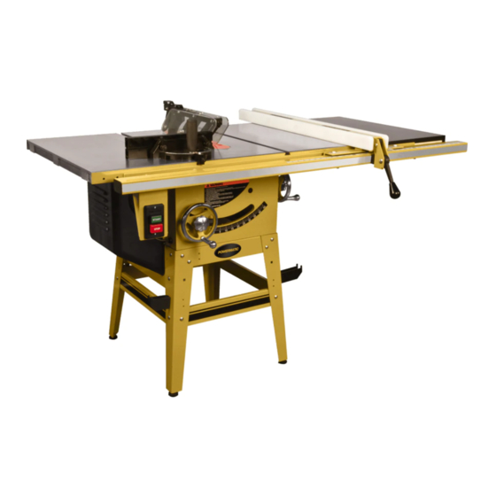
Operating Instructions and Parts Manual
10-inch Contractor Table Saw
Model 64B
WALTER MEIER (Manufacturing) Inc.
427 New Sanford Road
LaVergne, Tennessee 37086
Part No. M-1791229
Ph.: 800-274-6848
Revision A3 04/2012
www.powermatic.com
Copyright © 2012 Walter Meier (Manufacturing) Inc.
Advertisement
Table of Contents

Related Manuals for Powermatic 64B


Summary of Contents for Powermatic 64B
- Page 1 This .pdf document is bookmarked Operating Instructions and Parts Manual 10-inch Contractor Table Saw Model 64B WALTER MEIER (Manufacturing) Inc. 427 New Sanford Road LaVergne, Tennessee 37086 Part No. M-1791229 Ph.: 800-274-6848 Revision A3 04/2012 www.powermatic.com Copyright © 2012 Walter Meier (Manufacturing) Inc.
-
Page 2: Warranty And Service
This warranty covers only the initial purchaser of the product. WHAT IS THE PERIOD OF COVERAGE? The general POWERMATIC warranty lasts for the ti m e period specified in the product literature of each product. WHAT IS NOT COVERED? The Five Year Warranty does not cover products used for commercial, industrial or educational purposes. Products with a Five Year Warranty that are used for commercial, industrial or education purposes revert to a One Year Warranty. -
Page 3: Table Of Contents
16.4.1 Blade Guard and Miter Gauge Assemblies – Exploded View..............36 16.4.2 Blade Guard and Miter Gauge Assemblies – Parts List ................37 17.0 Electrical Connections............................38 17.1 Connections for 115 volt (64B Table Saw) ....................38 17.2 Connections for 230 volt (64B Table Saw) ....................39... -
Page 4: Safety Warnings
• Crystalline silica from bricks, cement and other masonry products. • Arsenic and chromium from chemically treated lumber. 3.0 Safety warnings Your risk of exposure varies, depending on how often you do this type of work. To 1. Read and understand the entire owner's reduce your exposure to these chemicals, manual before attempting assembly or work in a well-ventilated area and work with... -
Page 5: Kickback
24. Maintain a balanced stance at all times so Kickback can also result in the operator’s hands that you do not fall into the blade or other being pulled into the blade. moving parts. Do not overreach or use Kickback Prevention excessive force to perform any machine Tips to avoid the most common causes of operation. -
Page 6: About This Manual
4.0 About this manual This manual is provided by Walter Meier (Manufacturing) Inc. covering the safe operation and maintenance procedures for a Powermatic Model 64B Contractor Table Saw. This manual contains instructions on installation, safety precautions, general operating procedures, maintenance instructions and parts breakdown. -
Page 7: Glossary
5.0 Glossary Arbor: Metal shaft that connects the drive mechanism to the blade. Parallel: Two lines or surfaces lying at equal Bevel Edge Cut: Tilt of the saw arbor and blade distance from each other at every point along between 0° and 45° to perform an angled cutting their lengths. -
Page 8: Features
14 – Motor cover 7.0 Specifications Model number ................................64B Stock Numbers: Model 64B basic saw – with stand, no fence or rails ..................1791229 ® Model 64B basic saw – with 30” Rail Set, Accu-Fence , 27”x17” Wood Extension Table ......1791229K ®... - Page 9 Motor and Electricals: Motor type .................. totally enclosed fan cooled, induction, capacitor start Horsepower ............................1-3/4 HP (1.3 kW) Phase ................................... single Voltage ..........................115/230V (prewired 115V) Cycle ..................................60 Hz Motor speed ..............................3450 RPM Listed FLA (full load amps) ..........................15/7.5 A Starting amps ................................
-
Page 10: Setup And Assembly
Foot pads – V Fence hooks – W Miter gauge hook – X Small hook – Y Figure 4 – Hardware package (64B-HP) Stand hardware package (p/n 64B-SHP) Hex cap screws M8x20 – SHP-1 Pan head screws M5x15 – SHP-2 24 Carriage bolts M8x16 –... -
Page 11: Unpacking And Cleanup
Figure 6 Figure 7 – Stand hardware package (64B-SHP) 8.2 Unpacking and cleanup Open shipping container and check for shipping damage. Report any damage immediately to your distributor and shipping agent. Do not discard any shipping material until the Table Saw is assembled and running properly. -
Page 12: Stand Assembly
5. The four large holes on top of the stand 2. Note the orientation of the cut-out brace (P) should be reasonably aligned through the to the front brace with Powermatic label (R). upper braces for easy insertion of the The cut-out brace must be to the left, to screws. -
Page 13: Mounting Saw To Stand
Figure 9 8.4 Mounting saw to stand 8.5 Installing handwheels/hooks Refer to Figure 9 Refer to Figure 9. 1. Install a handwheel onto the tilting and The table saw is heavy! Get raising shafts, as shown. Fit the slot of the persons to assist you in lifting it. -
Page 14: Installing Table Extensions
8.6 Installing table extensions Refer to Figure 10. Figure 12 Figure 10 1. Start by tightening the three screws (17mm wrench) under the table extension that 1. Attach a table extension to the saw table. secure it to the saw table. Tighten these just Make sure edge bevel on table extension enough to hold the extension in place but faces front, to match that of saw table. -
Page 15: Switch Bracket
Figure 13 (10mm wrench). Figure 15 8.13 Installing and removing blade A blade is not provided with the 64B. 1. Using front handwheel, raise blade arbor Figure 13 fully and tighten lock knob. 8.11 Motor cover Refer to Figures 16 and 17. -
Page 16: Riving Knife
To install a riving knife: The 64B table saw is rated at 115/230V power, and is pre-wired for 115 volt. The table saw 1. Remove table insert, and raise arbor all the comes with a plug designed for use on a circuit way up. -
Page 17: Voltage Conversion
grounding instructions are not completely the electric cord or plug is necessary, do not connect the equipment-grounding conductor to a understood, or if in doubt as to whether the tool is properly grounded. Failure to comply live terminal. may cause serious or fatal injury. Use only 3-wire extension cords that have 3- prong grounding plugs and 3-pole receptacles 9.2 Voltage conversion... -
Page 18: Switch Lockout
9.4 Switch lockout 10.3 Miter gauge Refer to Figure 22. The table saw is equipped with a push-button switch that will accept a safety padlock, as 10.3.1 Setting miter angle shown in Figure 20. To safeguard your machine from unauthorized operation and accidental The precision miter gauge has a rack and pinion starting by young children, the use of a padlock adjustment for setting the angle. -
Page 19: Positive Blade Stops
If adjustment is necessary: 4. Adjust body (B) until it is perfectly square (90º) to miter slot. 5. Tighten lock handle (A). 6. Verify that scale indicator (G) reads 0º. If further adjustment is needed: 7. Loosen screw (F) and adjust indicator (G) until it reads 0º. -
Page 20: Riving Knife Alignment
Figure 26 Figure 28 10.5 Riving knife alignment 10.6 Low profile riving knife The riving knife must be aligned with the blade A low profile riving knife is included with your for proper and safe operation of the table saw. saw. -
Page 21: Belt Tension And Replacement
1. Loosen screw (A) and hex nut (B) and pivot motor upward to release tension on belt. If greater movement is needed, remove screw (A) and pivot motor further. 2. Replace belt. 3. Reinstall screw (A) and push down on motor to tension new belt. - Page 22 Confining cutoff piece when Support the work properly and hold it firmly crosscutting or ripping. against gauge or fence. Use a push stick Releasing workpiece before or push block when ripping short, narrow completing operation or not pushing work (6" width or less), or thin work. Use a pus h piece all the way past saw blade.
- Page 23 Figure 34 The rip fence (A, Fig. 34) should be set for the width of the cut by using the scale on the front rail, or by measuring the distance between blade Figure 36 (A) and fence (B). Stand out of line with saw blade and workpiece to avoid sawdust and When ripping long boards, use a support at front splinters coming off the blade or a potential...
- Page 24 Length stops should not be used on the free end of the workpiece in the cutoff area. Do not crosscut workpieces shorter than 6". Before starting a cut, be sure the miter gauge is securely clamped at the desired angle. Hold the workpiece firmly against the table and back against the miter gauge.
- Page 25 safety in avoiding a binding action between blade and table top. When beveling with the miter gauge, the workpiece must be held firmly to prevent creeping. Figure 43 The process of cutting 1/8" to 13/16" grooves in workpieces is accomplished by the use of a stacked dado blade set or an adjustable type blade mounted on the saw arbor.
-
Page 26: Safety Devices
12.0 Safety devices Feather board Feather boards can be purchased at most tool stores, or made by the operator to suit particular applications. The feather board (Figure 44) should be made of straight grain hardwood approximately 1" thick and 4" to 8" wide depending on the size of the machine. -
Page 27: Maintenance
Clean pitch and resin from saw blade. Weekly: Clean motor housing with compressed air. Wipe down fence rails with a dry silicon lubricant. Lubrication Refer to Figure 48. Lower the arbor all the way, and lubricate the following elements with a lithium grease every 12 months, or more frequently if needed. -
Page 28: Optional Accessories
Contact your dealer to order, or call Walter Meier at the phone number on the cover. p/n 1791088 – Dado insert for 64B table saw p/n 708118 – Universal mobile base Figure 49... -
Page 29: Troubleshooting The 64B Table Saw
15.0 Troubleshooting the 64B Table Saw Table 2 Trouble Probable Cause Remedy No incoming power. Check all plug connections. Table saw will not start. Fuse blown, or circuit breaker tripped. Replace fuse, or reset circuit breaker. Cord damaged. Replace cord. -
Page 30: Table And Cabinet Assembly – Exploded View
16.1.1 Table and Cabinet Assembly – Exploded View... -
Page 31: Table And Cabinet Assembly – Parts List
Size 1 ....64B-101 ....Table ....................1 2 ....64B-102 ....Table Extension .................. 2 ....64B-TIA....Table Insert Assembly (#3 thru #4) ............1 3 ....64B-103 ....Table Insert ..................1 4 ....TS-1522011 ....Socket Set Screw ..........M5x5 ......6 5 ....64B-105 ....Cover ....................1 6 .... -
Page 32: Motor And Trunnion Assembly - Exploded View
16.2.1 Motor and Trunnion Assembly – Exploded View... -
Page 33: Motor And Trunnion Assembly - Parts List
1 ....64B-124 ....Lock Knob ..................1 2 ....3520B-126 ....Handle ....................1 3 ....64B-107 ....Handwheel ..................1 4 ....64B-117 ....Spring Pin ............Ø4x25 mm ....1 5 ....64B-205 ....Lead Screw ..................1 6 ....64B-206 ....Thrust Bearing ..........51104 ......1 7 .... - Page 34 63 .... 64B-263 ....Thread Housing .................. 1 64 .... 64B-264 ....Bushing....................1 65 .... 6290630 ....Strain Relief .............7W-2......1 66 .... 64B-266 ....Hex Nut (L.H Thread) ........M14-2.0P ....1 67 .... 64B-267 ....Key ..............5x5x25 mm ....1 68 .... 64B-268 ....Motor Pulley ..................1 69 ....
-
Page 35: Stand Assembly - Exploded View
4 ....64B-304 ....Upper Long Brace................1 5 ....64B-305 ....Lower Short Brace (includes stripe)............2 6 ....64B-306 ....Lower Long Brace (includes stripe) ............2 7 ....64B-307 ....Powermatic Nameplate Label ......1-1/2”W x 10”L.... 1 8 ....64B-308 ....Miter Gauge Hook................1 9 .... -
Page 36: Blade Guard And Miter Gauge Assemblies - Exploded View
16.4.1 Blade Guard and Miter Gauge Assemblies – Exploded View... -
Page 37: Blade Guard And Miter Gauge Assemblies - Parts List
Index No Part No Description Size ....64B-BGA ....Blade Guard Assembly (#1 thru #31) ........... 1 1 ....64B-401 ....Riving Knife ..................1 ....64B-UGA ....Upper Guard Assembly (#2 thru #31) ........... 1 2 ....64B-402 ....Support Arm ..................1 3 .... -
Page 38: Electrical Connections
17.0 Electrical Connections 17.1 Connections for 115 volt (64B Table Saw) 400MFD 125 VAC 30uf 250 VAC 115V... -
Page 39: Connections For 230 Volt (64B Table Saw)
17.2 Connections for 230 volt (64B Table Saw) 400MFD 125 VAC 30uf 250 VAC 230V... - Page 40 WALTER MEIER (Manufacturing) Inc. 427 New Sanford Road LaVergne, Tennessee 37086 Phone: 800-274-6848 www.powermatic.com www.waltermeier.com...
Need help?
Do you have a question about the 64B and is the answer not in the manual?
Questions and answers