Sign In
Upload
Download
Table of Contents
Contents
Add to my manuals
Delete from my manuals
Share
URL of this page:
HTML Link:
Bookmark this page
Add
Manual will be automatically added to "My Manuals"
Print this page
×
Bookmark added
×
Added to my manuals
Manuals
Brands
Toa Manuals
Amplifier
A-1803
Operating instructions manual
Toa A-1803 Operating Instructions Manual
Pa amplifier
Hide thumbs
1
Table Of Contents
2
3
4
5
6
7
8
9
10
11
12
13
14
15
16
page
of
16
Go
/
16
Contents
Table of Contents
Bookmarks
Table of Contents
Table of Contents
1 Safety Precautions
2 General Description
3 Features
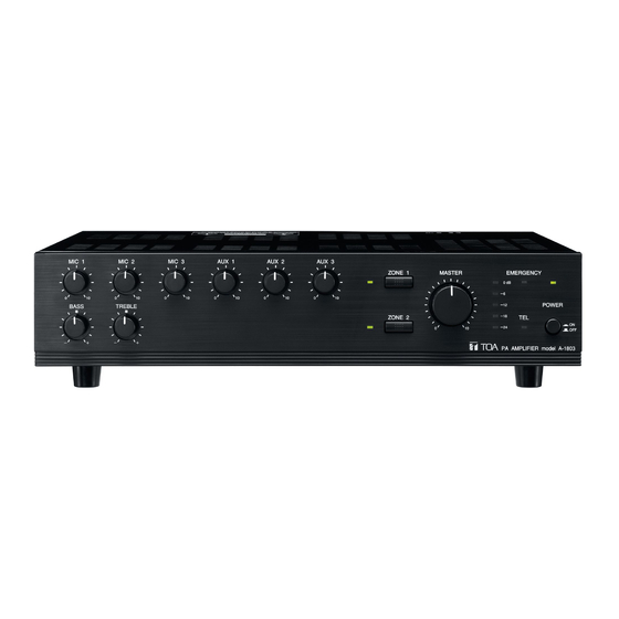
4 Nomenclature and Functions
Front
Rear
5 Connections
Speaker Connections
Remote Power ON/OFF Control Connection
Emergency Input and Control Input Terminal Connections
Telephone Paging Input Terminal Connection
6 Function Switch Settings
7 Chime Function
MIC 1 Chime Tone
Telephone Paging Chime Tone
8 Priority Functions
Telephone Paging Input (Voice-Activated Priority)
Microphone Input (Voice-Activated Priority)
Paging Microphone Input
Emergency Control Input
Telephone Paging Control Input
9 Speaker Zone Selection
10 Installation
11 Rack Mounting
12 Control Settings
13 Dimensional Diagram
14 Internal Modifications
Turning On/Off LINE out 1 (2) in Conjunction with ZONE 1 (2) Selector Switch
Turning the Power off to Disable Broadcast with EMRGENCY Control Activation
Convert TEL PAGING Input into Transformer-Balanced Type
15 Block Diagram
16 Specifications
Accessories
Optional Products
Advertisement
Quick Links
1
General Description
2
Speaker Connections
3
Connections
4
Telephone Paging Input Terminal Connection
5
Speaker Zone Selection
6
Block Diagram
Download this manual
PA AMPLIFIER
Please follow the instructions in this manual to obtain the optimum results from this unit.
We also recommend that you keep this manual handy for future reference.
OPERATING INSTRUCTIONS
A-1803
A-1806
A-1812
Table of
Contents
Previous
Page
Next
Page
1
2
3
4
5
Advertisement
Table of Contents
Need help?
Do you have a question about the A-1803 and is the answer not in the manual?
Ask a question
Questions and answers
Related Manuals for Toa A-1803
Amplifier Toa A-1712 Operating Instructions Manual
Pa amplifier (12 pages)
Amplifier Toa A-1706 Operating Instructions Manual
Pa amplifier (12 pages)
Amplifier Toa A-1724 Operating Instructions Manual
Pa amplifier (12 pages)
Amplifier TOA A-1806 Operating Instructions Manual
Pa amplifier (16 pages)
Amplifier TOA A-1812 Operating Instructions Manual
Pa amplifier (16 pages)
Amplifier TOA A-1503 Operating Instructions Manual
Toa a-1503; a-1506; a-1512 pa amplifier (13 pages)
Amplifier TOA A-1512 Operating Instructions Manual
Toa a-1503; a-1506; a-1512 pa amplifier (13 pages)
Amplifier Toa A-1031 Operating Instructions Manual
Basic pa amplifier (8 pages)
Amplifier Toa A-1240SS AS Operating Instructions Manual
(8 pages)
Amplifier Toa M-9000M2 Installation And Operating Instructions Manual
9000m2 series (160 pages)
Amplifier Toa A-2060 CU Operating Instructions Manual
Pa amplifiers (12 pages)
Amplifier Toa A-2060 CE Operating Instructions Manual
Pa amplifiers (12 pages)
Amplifier Toa A-2120DT Series Instruction Manual
Digital (12 pages)
Amplifier Toa A-812D Operating Instructions Manual
Mixer amplifier (28 pages)
Amplifier Toa A-5006A Quick Manual
(9 pages)
Amplifier Toa A-2060 CE-AU Operating Instructions Manual
(12 pages)
This manual is also suitable for:
A-1806
A-1812
Table of Contents
Print
Rename the bookmark
Delete bookmark?
Delete from my manuals?
Login
Sign In
OR
Sign in with Facebook
Sign in with Google
Upload manual
Upload from disk
Upload from URL


Need help?
Do you have a question about the A-1803 and is the answer not in the manual?
Questions and answers