Sign In
Upload
Download
Table of Contents
Contents
Add to my manuals
Delete from my manuals
Share
URL of this page:
HTML Link:
Bookmark this page
Add
Manual will be automatically added to "My Manuals"
Print this page
×
Bookmark added
×
Added to my manuals
Manuals
Brands
Toa Manuals
Amplifier
A-3506D
Operating instructions manual
Toa A-3506D Operating Instructions Manual
Hide thumbs
1
Table Of Contents
2
3
4
5
6
7
8
9
10
11
12
13
14
15
16
17
18
19
20
21
22
23
24
25
26
27
28
page
of
28
Go
/
28
Contents
Table of Contents
Bookmarks
Table of Contents
Table of Contents
1 Safety Precautions
2 General Description
3 Features
4 Handling Precautions
5 Installation Precautions
6 Nomenclature and Functions
Front
Rear
7 Connections
Speaker Connection
Input Terminal Connections and Settings
Connecting to the Power Remote Control Output Terminal
Connecting to the Emergency Control Output Terminal
Connecting to the Zone Control IN/OUT Terminal
Connecting to the Control Input Terminal
Connecting the External Equipment between the Line Output and the Power Amplifier
Removable Terminal Plug Connection
8 Settings
Zone Selection Button Setting
Line Output Interlock Switch Setting
Audio Detection Function Setting
Broadcast Mode Setting for Input 1
9 Volume Adjustment
10 Speaker Zone Selection
11 Installing to an Equipment Rack
12 Control Settings
13 Priority Broadcast Function
Priority Broadcast
Emergency Broadcast
Normal Broadcast
Relationship between Priority Broadcast by Control Input/Emergency Broadcast and Power On/Off
Factory-Preset Operation
Operation When the Priority Broadcast Function Is Activated by Audio Detection
14 Block Diagram
15 Specifications
Accessories
Optional Products
Advertisement
Quick Links
Download this manual
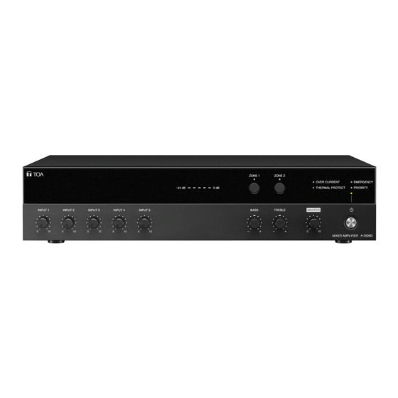
OPERATING INSTRUCTIONS
MIXER AMPLIFIER
A-3506D, A-3512D, A-3524D, A-3548D
The figure represents the A-3548D.
Thank you for purchasing TOA's Mixer amplifier.
Please carefully follow the instructions in this manual to ensure long, trouble-free use of your equipment.
Table of
Contents
Previous
Page
Next
Page
1
2
3
4
5
Advertisement
Table of Contents
Need help?
Do you have a question about the A-3506D and is the answer not in the manual?
Ask a question
Questions and answers
Related Manuals for Toa A-3506D
Amplifier Toa A-3000D-AS Series Instruction Manual
Digital mixer amplifier (16 pages)
Amplifier Toa A-3224D-AS 1 Instruction Manual
Digital mixer amplifier (16 pages)
Amplifier Toa A-3606D Operating Instructions Manual
Mixer amplifier (32 pages)
Amplifier Toa A-3612D Operating Instructions Manual
Mixer amplifier (32 pages)
Amplifier Toa A-3624D Operating Instructions Manual
Mixer amplifier (32 pages)
Amplifier Toa A-3648D Operating Instructions Manual
Mixer amplifier (32 pages)
Amplifier Toa A-3512D Operating Instructions Manual
(28 pages)
Amplifier Toa A-3524D Operating Instructions Manual
(28 pages)
Amplifier Toa A-3548D Operating Instructions Manual
(28 pages)
Amplifier Toa A-3212DZ-EB 1CE Instruction Manual
(12 pages)
Amplifier Toa M-9000 Operating Instructions Manual
9000 series (138 pages)
Amplifier Toa A-903A Operating Instructions Manual
900 series mixer power amplifier (16 pages)
Amplifier Toa A-2060 CU Operating Instructions Manual
(13 pages)
Amplifier Toa A-230 HV Operating Instructions Manual
(8 pages)
Amplifier Toa A-2060 CE-AU Operating Instructions Manual
(12 pages)
Amplifier Toa A-2240 CE-AU Operating Instructions Manual
(12 pages)
This manual is also suitable for:
A-3512d
A-3524d
A-3548d
Table of Contents
Print
Rename the bookmark
Delete bookmark?
Delete from my manuals?
Login
Sign In
OR
Sign in with Facebook
Sign in with Google
Upload manual
Upload from disk
Upload from URL


Need help?
Do you have a question about the A-3506D and is the answer not in the manual?
Questions and answers