Table of Contents
Advertisement
700 SERIES AMPLIFIERS
TABLE OF CONTENTS
1. IMPORTANT SAFETY INSTRUCTIONS ........................................................................................ 2
2. SAFETY PRECAUTIONS ............................................................................................................... 2
3. GENERAL DESCRIPTION ............................................................................................................. 4
4. FEATURES ..................................................................................................................................... 4
Front ................................................................................................................................................ 4
Rear ................................................................................................................................................ 5
6.1. Speaker Connections ............................................................................................................... 6
6.2. Remote Volume Control Connection ........................................................................................ 6
6.3. Remote Power ON/OFF Control Connection ........................................................................... 7
6.4. Mute Control Connection ......................................................................................................... 7
7. INSTALLATION .............................................................................................................................. 7
8. RACK MOUNTING ......................................................................................................................... 8
9. CONTROL SETTINGS ................................................................................................................... 8
10. DIMENSIONAL DIAGRAM ............................................................................................................. 8
11. BLOCK DIAGRAM ......................................................................................................................... 9
12. SPECIFICATIONS ........................................................................................................................ 10
Accessories ................................................................................................................................... 10
Optional products .......................................................................................................................... 10
Thank you for purchasing TOA's 700 Series Amplifiers.
Please carefully follow the instructions in this manual to ensure long, trouble-free use of your equipment.
OPERATING INSTRUCTIONS
A-706, A-712, A-724
Advertisement
Table of Contents

Summary of Contents for Toa A-706, A-712, A-724
-
Page 1: Table Of Contents
12. SPECIFICATIONS ... 10 Accessories ... 10 Optional products ... 10 Thank you for purchasing TOA's 700 Series Amplifiers. Please carefully follow the instructions in this manual to ensure long, trouble-free use of your equipment. OPERATING INSTRUCTIONS A-706, A-712, A-724... -
Page 2: Important Safety Instructions
1. IMPORTANT SAFETY INSTRUCTIONS • Read these instructions. • Keep these instructions. • Heed all warnings. • Follow all instructions. • Do not use this apparatus near water. • Clean only with dry cloth. • Do not block any ventilation openings. Install in accordance with the manufacture's instructions. •... - Page 3 surface. Doing so may result in the unit falling down, causing personal injury and/or property damage. When the Unit is in Use • Should the following irregularity be found during use, immediately switch off the power, disconnect the power supply plug from the AC outlet and contact your nearest TOA dealer.
-
Page 4: General Description
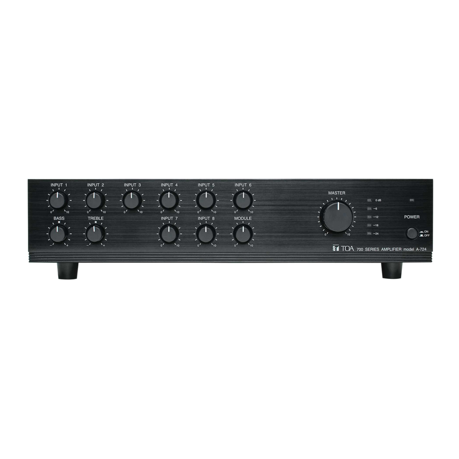
3. GENERAL DESCRIPTION Equipped with 6 LINE/MIC selectable inputs, 2 LINE inputs and 1 MODULE input, the A-706, A-712, and A- 724 PA amplifiers are designed to suit PA system applications such as announcements, BGM and broadcasting in churches, large rooms and factories. 4. -
Page 5: Rear
[Rear] 9. AC inlet Connect the supplied power cord. 10. Remote control connector Removable terminal block. (1) Remote volume control terminals [REMOTE VOLUME] Connecting a 10 kΩ linear taper volume control across these terminals will allow remote control of preamplifier output and speaker output levels. (2) Power remote control terminals [POWER REMOTE] Allows remote control of the unit's power... -
Page 6: Connections
17. Module input slot Accepts TOA's 900 series module. 18. Functional ground terminal Hum noise may be generated when external equipment is connected to the unit. Connecting this terminal to the functional ground terminal of the external equipment may reduce the hum noise. -
Page 7: Remote Power On/Off Control Connection
6.3. Remote Power ON/OFF Control Connection To perform this control, be sure to turn the power switch OFF. Shorting the power remote control terminals turns the power on, and opening them turns the power off. With the power switch ON, the power on/off cannot be remotely controlled. -
Page 8: Rack Mounting
8. RACK MOUNTING To mount the unit in a standard 19" equipment rack, use the optional MB-25B Rack Mounting Bracket. Attach the MB-25B to the unit using the supplied 4 screws. When using other screws, each screw must be shorter than 16 mm. M4 x 16 Machine screw included in MB-25B MB-25B 9. -
Page 9: Block Diagram
11. BLOCK DIAGRAM... -
Page 10: Specifications
12. SPECIFICATIONS [A-706] Power Source Rated Output Power/Current Consumption Frequency Response Distortion Input Output Phantom Power (+23 V DC) S/N Ratio (Band pass: 20 – 20,000 Hz) Tone Control Control Input Indicator Operating Temperature Finish Dimensions Weight * 0 dB = 1 V Note: The design and specifications are subject to change without notice for improvement. - Page 11 [A-712] Power Source Rated Output Power/Current Consumption Frequency Response Distortion Input Output Phantom Power (+23 V DC) S/N Ratio (Band pass: 20 – 20,000 Hz) Tone Control Control Input Indicator Operating Temperature Finish Dimensions Weight * 0 dB = 1 V Note: The design and specifications are subject to change without notice for improvement.
- Page 12 [A-724] Power Source Rated Output Power/Current Consumption Frequency Response Distortion Input Output Phantom Power (+23 V DC) S/N Ratio (Band pass: 20 – 20,000 Hz) Tone Control Control Input Indicator Operating Temperature Finish Dimensions Weight * 0 dB = 1 V Note: The design and specifications are subject to change without notice for improvement.


Need help?
Do you have a question about the A-706, A-712, A-724 and is the answer not in the manual?
Questions and answers