Table of Contents
Advertisement
• Important operating and
maintenance instructions
included.
WARNING: If the information in these
instructions is not followed exactly, a fi re
or explosion may result causing property
damage, personal injury, or death.
• Do not store or use gasoline or other fl am-
mable vapors and liquids in the vicinity of this
or any other appliance.
• What to do if you smell gas
- Do not try to light any appliance.
Do not touch any electrical switch. Do not
use any phone in your building.
- Immediately call your gas supplier from a
neighbor's phone. Follow the gas supplier's
instructions.
- If you cannot reach your gas supplier, call
the fi re department.
• Installation and service must be performed
by a qualifi ed installer, service agency, or the
gas supplier.
Installation and service of this appliance should be
performed by qualifi ed personnel. Hearth & Home
Technologies suggests NFI certifi ed or factory-trained
professionals, or technicians supervised by an NFI
certifi ed professional.
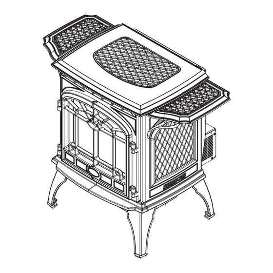
GARNET-T
DIRECT VENT ROOM HEATER
Owner's Manual
Installation and Operation
Model:
GARNET-MBK
GARNET-D-MBK
GARNET-D-PMH
GARNET-D-CSB
CAUTION
DO NOT DISCARD THIS MANUAL
• Read, understand and
follow these instructions
for safe installation and
operation.
Quadra-Fire • GARNET-T • 7016-127 Rev. i • 12/11
• Leave this manual with
party responsible for use
and operation.
WARNING
• Do not touch glass until it is cooled
• NEVER allow children to touch glass
• Keep children away
• CAREFULLY SUPERVISE children in the same room as
appliance
• Alert children and adults to hazards of high temperatures
High temperatures may ignite clothing or other
fl ammable materials.
• Keep clothing, furniture, draperies and other combustibles
away.
In the Commonwealth of Massachusetts:
• installation must be performed by a licensed plumber or gas
fi tter.
See Table of Contents for additional Commonwealth of Mas-
sachusetts requirements.
This appliance may be installed as an OEM installation in manu-
factured home (USA only) or mobile home and must be installed in
accordance with the manufacturer's instructions and the manufac-
tured home construction and safety standard, Title 24 CFR, Part 3280
or Standard for Installation in Mobile Homes, CAN/CSA Z240MH.
This appliance is only for use with the type(s) of gas indicated on
the rating plate.
R
O-T L
O-T
Tested and
Portland
Oregon USA
Listed by
C
US
OMNI-Test Laboratories, Inc.
HOT SURFACES!
Glass and other surfaces are
hot during operation AND
cool down.
Hot glass will cause
burns.
Advertisement
Table of Contents

Related Manuals for Quadra-Fire GARNET-MBK


Summary of Contents for Quadra-Fire GARNET-MBK
-
Page 1: Installation And Operation
Standard for Installation in Mobile Homes, CAN/CSA Z240MH. professionals, or technicians supervised by an NFI This appliance is only for use with the type(s) of gas indicated on certifi ed professional. the rating plate. Quadra-Fire • GARNET-T • 7016-127 Rev. i • 12/11... - Page 2 Date of Manufacture / Date du Manufacturier Manufactured Date 2008 2009 2010 Made in U.S.A. / Fait Aux États-Unis DO NOT REMOVE THIS LABEL / NE PAS ENLEVER L’ÉTIQUETTE 7016-128 Quadra-Fire • GARNET-T • 7016-127 Rev. i • 12/11 Page 2...
-
Page 3: Table Of Contents
A. Fuel Conversions ........25 D. Service Parts List ........48 B. Gas Pressures ........27 E. Limited Lifetime Warranty ....52 C. Gas Connection........27 F. Contact Information ......54 = Contains updated information. Quadra-Fire • GARNET-T • 7016-127 Rev. i • 12/11 Page 3... -
Page 4: Section 1: Listing And Code Approvals
Immediately call a qualifi ed service technician to inspect the unit and to replace any part of the control system and any gas control which has been under water. Page 4 Quadra-Fire • GARNET-T • 7016-127 Rev. i • 12/11... -
Page 5: Requirements For The Commonwealth Of Massachusetts
(1/2) inch in size, “GAS VENT DIRECTLY BELOW. KEEP CLEAR OF ALL OBSTRUCTIONS.” See Gas Connection section for additional Common- wealth of Massachusetts requirements. Page 5 Quadra-Fire • GARNET-T • 7016-127 Rev. i • 12/11... -
Page 6: Section 2: Getting Started
Framing Material Flat Blade Screwdriver Voltmeter Plumb Line Gloves Level Safety Glasses Manometer Tape Measure Caulking material (300ºF minimum continuous exposure rating) Non-corrosive Leak Check Solution or combustible gas detector Page 6 Quadra-Fire • GARNET-T • 7016-127 Rev. i • 12/11... -
Page 7: Section 3: Appliance Location & Clearances A. Selecting Appliance Location
USE wood fl ooring, ceramic tile, brick hearth manufacturer for maximum temperature allowed on flooring or high pressure laminate fl ooring applied directly over the sub-fl ooring material. surfaces. Page 7 Quadra-Fire • GARNET-T • 7016-127 Rev. i • 12/11... -
Page 8: Section 4: Termination Locations
In a staggered installation with both gas and wood or fuel oil terminations, the wood or fuel oil termination cap must be higher than the gas termination cap. Figure 4.2 Multiple Vertical Termination Page 8 Quadra-Fire • GARNET-T • 7016-127 Rev. i • 12/11... - Page 9 NOTE 3: Location of the vent termination must not interfere with access CAUTION: IF EXTERIOR WALLS ARE FINISHED WITH to the electrical service. VINYL SIDING, IT IS SUGGESTED THAT A VINYL PRO- Figure 4.4 TECTOR KIT BE INSTALLED. Page 9 Quadra-Fire • GARNET-T • 7016-127 Rev. i • 12/11...
-
Page 10: Section 5: Vent Information
• Use separate vent system for this appliance. pipe before termination cap. May impair safe operation of this appliance or other appliances connected to the fl ue. • Horizontal pipe installed level with 1/4 in. rise. Page 10 Quadra-Fire • GARNET-T • 7016-127 Rev. i • 12/11... -
Page 11: How To Use The Vent Graph
6 in. (152mm) 30 in. (762mm) Maximum Horizontal run with no Minimum starter pipe vertical pipe and with 1/4 in. (6mm) rise per foot. Must use approved Termination Cap. Figure 5.2 Page 11 Quadra-Fire • GARNET-T • 7016-127 Rev. i • 12/11... -
Page 12: Horizontal Termination
45° Elbow 2 in. (51mm) Clearance from stove corner to combustible wall Male Locking Lugs Figure 5.4 2 in. (51mm) Clearance from stove corner to combustible wall. Figure 5.3 Page 12 Quadra-Fire • GARNET-T • 7016-127 Rev. i • 12/11... - Page 13 (2) The location of the horizontal vent termination on an exterior wall must meet all local and national building Page 13 Quadra-Fire • GARNET-T • 7016-127 Rev. i • 12/11...
- Page 14 Use the two sheet metal screws provided to connect the strips to the pipe section (Figure 5.9). Page 14 Quadra-Fire • GARNET-T • 7016-127 Rev. i • 12/11...
-
Page 15: Vertical Termination
NOTE: Maximum number of 45° elbows permitted for a vertical installation is eight, provided their installation does not decrease maximum allowable horizontal run (as specified by vent graph, on page 11). Page 15 Quadra-Fire • GARNET-T • 7016-127 Rev. i • 12/11... - Page 16 Step 2. The hole should be of sufficient size to meet problem. the minimum requirements for clearance to combustibles, as specified. Continue to assemble lengths of pipe and elbows Page 16 Quadra-Fire • GARNET-T • 7016-127 Rev. i • 12/11...
- Page 17 Figure 5.13. Nails Ceiling Firestop Minimum 1 in. (25mm) Clearance Minimum 1 in. (25mm) Clearance Minimum 1 in. (25mm) Clearance Minimum 1 in. (25mm) Clearance Figure 5.16 Page 17 Quadra-Fire • GARNET-T • 7016-127 Rev. i • 12/11...
- Page 18 Ensure that all pipe and elbow connections are in their fully twist-locked position. Assemble as instructed. Cathedral Ceiling Support Screws Figure 5.19 Page 18 Quadra-Fire • GARNET-T • 7016-127 Rev. i • 12/11...
- Page 19 Sheet Metal Screws Step 7. The connection between the appliance and the retro connector may be completed with sections of direct vent Figure 5.21 pipe. Page 19 Quadra-Fire • GARNET-T • 7016-127 Rev. i • 12/11...
-
Page 20: Existing Masonry Chimney
(76mm) Flex Liner Co-Axial to Co-Linear Connector Air Intake Section" *In the Commonwealth of Massachusetts, the word damper shall be replaced with the words fl ue restrictor. Figure 5.24 Page 20 Quadra-Fire • GARNET-T • 7016-127 Rev. i • 12/11... - Page 21 (Figure 5.27, on the larger than the top of the chimney, cut and fold flashing as next page). needed to fit chimney (Figure 5.26). Page 21 Quadra-Fire • GARNET-T • 7016-127 Rev. i • 12/11...
- Page 22 The connection between the appliance and the retro opening and the mounting holes line up with the masonry connector may be completed with sections of direct vent wall. pipe. Page 22 Quadra-Fire • GARNET-T • 7016-127 Rev. i • 12/11...
-
Page 23: Slim Line Wall Thimble
Bend the heat shield as shown. crete, or other types of sidings. NOTE: Wear leather gloves when bending the heat shield to prevent injury. Page 23 Quadra-Fire • GARNET-T • 7016-127 Rev. i • 12/11... - Page 24 MINIMUM OF 6 IN. (152 MM) OF PIPE THROUGH WALL WALL THIMBLE INTERIOR WALL 2 IN. (51MM) CLEARANCE FROM REAR OF STOVE CENTER LINE TERMINATION CAP HEAT SHIELD OVER TOP HALF OF PIPE TRIM RING Figure 5.33 Page 24 Quadra-Fire • GARNET-T • 7016-127 Rev. i • 12/11...
-
Page 25: Section 6: Gas Information
DO NOT remove the screws from the burner top. your gas type and venting. Lift the burner up and out of the fi rebox. PROPANE NATURAL GAS Reinstall burner. Page 25 Quadra-Fire • GARNET-T • 7016-127 Rev. i • 12/11... -
Page 26: Valve Regulator Replacement
Identification Label Ensure that the rubber gasket (D) is properly Figure 6.6 positioned and install the new HI/LO pressure regulator assembly to the valve using the new screws (E) supplied Page 26 Quadra-Fire • GARNET-T • 7016-127 Rev. i • 12/11... -
Page 27: Gas Pressures
You must supply a manual shut-off valve in a visible location at the suggested input pressure listed above. Contact the within 3 feet (914mm) of the appliance. local gas supplier if the regulator is at an improper pressure. Page 27 Quadra-Fire • GARNET-T • 7016-127 Rev. i • 12/11... - Page 28 Fire hazard. Do NOT change the valve settings. • This valve has been preset at the factory. • Changing valve settings may result in fi re hazard or bodily injury. Page 28 Quadra-Fire • GARNET-T • 7016-127 Rev. i • 12/11...
-
Page 29: Section 7: Electrical Information
18 feet Keep wire lengths as short as possible by removing any excess wire length. Low voltage and 110 VAC voltage cannot be shared within the same wall box. Page 29 Quadra-Fire • GARNET-T • 7016-127 Rev. i • 12/11... - Page 30 • Replace damaged wire with type 105 Wiring errors can cause improper and dangerous operation. rated wire. Verify proper operation after servicing. • Wire must have high temperature insulation. Page 30 Quadra-Fire • GARNET-T • 7016-127 Rev. i • 12/11...
-
Page 31: Section 8: Appliance Setup
Use a 5/32 in. 4mm) Allen wrench to adjust legs located in the back of the fi rebox. Reuse the screws to install up and down to desired level. the fl ue restrictor. Page 31 Quadra-Fire • GARNET-T • 7016-127 Rev. i • 12/11... -
Page 32: Accessories
Place the notch in the Rear Log over the pilot assembly. embers on top of each other. Push the log all the way to the rear of the firebox. NOTE: Do not block gas ports. Page 32 Quadra-Fire • GARNET-T • 7016-127 Rev. i • 12/11... -
Page 33: Glass Replacement
Holding the blower in place, attach it to the 8 - 12 inch Glass Tape appliance with four of the screws provided. 9 - 1 Zip Tie 10 - Bracket #1 11 - Snap Disc Bracket Page 33 Quadra-Fire • GARNET-T • 7016-127 Rev. i • 12/11... - Page 34 Pull the cover forward, down and out. Attach the snap disc bracket to the stud located under the left side of the appliance using the 10-32 nut. Page 34 Quadra-Fire • GARNET-T • 7016-127 Rev. i • 12/11...
- Page 35 Thermal Disc WHITE Fan Speed Control Power Cord (110 VAC) BLACK BLACK GREEN Ground Strain Relief BLACK Bushing Fan Assembly Figure 8.15 Blower Wiring Diagram Page 35 Quadra-Fire • GARNET-T • 7016-127 Rev. i • 12/11...
-
Page 36: Ignition Module Access And Battery
fl ames shorter and more active. Closing the damper makes the fl ames taller and less active. After adjustment, tighten nut to lock in place. Page 36 Quadra-Fire • GARNET-T • 7016-127 Rev. i • 12/11... -
Page 37: Section 9: Operating Instructions
• Alert children and adults to hazards of high temperatures. • Do NOT operate with protective barriers open or removed. • Keep clothing, furniture, draperies and other combustibles away. Page 37 Quadra-Fire • GARNET-T • 7016-127 Rev. i • 12/11... -
Page 38: Lighting Appliance
1. Set the thermostat to lowest setting. 2. Turn off all electric power to the appliance if service is to be performed. 3. Push in gas control knob slightly and turn clockwise to "OFF" position. Page 38 Quadra-Fire • GARNET-T • 7016-127 Rev. i • 12/11... -
Page 39: After Appliance Is Lit
Noise is caused by metal expanding and contracting as it heats up and cools down, similar to the sound produced by a furnace or heating duct. This noise does not affect the operation or longevity of the appliance. Page 39 Quadra-Fire • GARNET-T • 7016-127 Rev. i • 12/11... -
Page 40: Section 10: Troubleshooting
With the pilot in the ON position, disconnect the thermopile leads from the valve. Take a reading at the thermopile leads. The reading should be 325 millivolts minimum. Replace the thermopile if the reading is below the minimum. Page 40 Quadra-Fire • GARNET-T • 7016-127 Rev. i • 12/11... - Page 41 Ensure that no debris has been placed at the base of, or in the area of the air holes in the center of the base pan beneath the burner. Ensure that the glass is tightened properly on the appliance, particu- larly on top corners. Page 41 Quadra-Fire • GARNET-T • 7016-127 Rev. i • 12/11...
- Page 42 • Odors WARNING Inspect external vent cap regularly. • Ensure no debris blocks cap. • Combustible materials blocking cap may ignite. • Restricted air fl ow affects burner operation. Page 42 Quadra-Fire • GARNET-T • 7016-127 Rev. i • 12/11...
-
Page 43: Maintenance Tasks
4. Inspect for corrosion or separation. 5. Verify weather stripping, sealing and fl ashing remains intact. Remote Controls 1. Verify operation of remote. 2. Replace batteries in remote transmitters and battery-powered receivers. Page 43 Quadra-Fire • GARNET-T • 7016-127 Rev. i • 12/11... -
Page 44: Section 12: Reference Materials
Dimensions are actual appliance dimensions. Use for reference only. For clearances refer to Section 3. Location Inches Millimeter Location Inches Millimeter 27-3/4 17-3/8 17-7/8 23-5/8 15-3/8 17-3/4 Figure 12.1 Appliance Dimensions Page 44 Quadra-Fire • GARNET-T • 7016-127 Rev. i • 12/11... -
Page 45: Vent Components Diagram
12-17 in. (305-432mm) 3-3/4 in. (95mm) SLP36M SLP48M SLP4M SLP24M SLP6AM 4 in. (102 mm) inner pipe 6-5/8 in. (168 mm) outer pipe Figure 12.2 SL-D Series Vent Components Page 45 Quadra-Fire • GARNET-T • 7016-127 Rev. i • 12/11... -
Page 46: Vent Components List
3” x 35’ Flex Extension 2280 4” x 35’ Flex Extension 2281 45° Elbow, Galvanized SLP45M 45° Elbow, Black SLP45-BK See Swivel 45° Elbow, Swivel, Galvanized 46DVA-E45 45° Elbow, Swivel, Black 46DVA-E45B Page 46 Quadra-Fire • GARNET-T • 7016-127 Rev. i • 12/11... - Page 47 Each pipe manufacturer has their own list of parts for kits. SL is not interchangeable with SLP. Stove Adaptor Kit (Vertical Cap Kit) Includes 30’-4” ex, adapters, wall thimble, masonry, ZC ashing, 991DA vertical cap. Page 47 Quadra-Fire • GARNET-T • 7016-127 Rev. i • 12/11...
-
Page 48: Service Parts List
6/04 - Active 839-1151 4/03 - 5/04 Porcelain Mahogany GARNET-D-PMH 6/04 - Active Powder Coat Linden Green GARNET-D-CLG 6/04 - 4/06 Log Set Assembly Part number list on following page. Page 48 Quadra-Fire • GARNET-T • 7016-127 Rev. i • 12/11... - Page 49 Burner w/Neck Assembly SRV7016-033 Gasket, Pilot Post 0071237555 7000-196 Pilot Assembly - NG 230-1781 Thermocouple 200-2950 Thermopile/Generator, Millivolt 842-0250 Shutter Assembly SRV7016-034 Additional service part numbers appear on following page. Page 49 Quadra-Fire • GARNET-T • 7016-127 Rev. i • 12/11...
- Page 50 Burner w/Neck Assembly SRV7016-033 Gasket, Pilot Post 0071237555 7000-196 Pilot Assembly - NG 230-1781 Thermocouple 200-2950 Thermopile/Generator, Millivolt 842-0250 Shutter Assembly SRV7016-034 Additional service part numbers appear on following page. Page 50 Quadra-Fire • GARNET-T • 7016-127 Rev. i • 12/11...
- Page 51 Pre 0071237555 7016-164 Pilot Spacer Post 0071237556 7016-165 Pilot Spacer 7010-175 Plug, Orifi ce Insert #49 842-1220 Relief Door Bracket 7016-121 Additional service part numbers appear on following page. Page 51 Quadra-Fire • GARNET-T • 7016-127 Rev. i • 12/11...
-
Page 52: Limited Lifetime Warranty
3 years Firebox and heat exchanger Lifetime All replacement parts 90 Days beyond warranty period See conditions, exclusions, and limitations on next page. 4021-645C 12-29-10 Page 1 of 2 Page 52 Quadra-Fire • GARNET-T • 7016-127 Rev. i • 12/11... - Page 53 E. Limited Lifetime Warranty (continued) WARRANTY CONDITIONS: WARRANTY EXCLUSIONS: This warranty is void if: LIMITATIONS OF LIABILITY: 4021-645C 12-29-10 Page 2 of 2 Page 53 Quadra-Fire • GARNET-T • 7016-127 Rev. i • 12/11...
-
Page 54: Contact Information
Quadra-Fire, a brand of Hearth & Home Technologies Inc. 7571 215 Street West, Lakeville, MN 55044 www.quadrafi re.com Please contact your Quadra-Fire dealer with any questions or concerns. For the location of your nearest Quadra-Fire dealer, please visit www.quadrafi re.com. CAUTION Do NOT discard this manual.
Need help?
Do you have a question about the GARNET-MBK and is the answer not in the manual?
Questions and answers