Table of Contents
Advertisement
Installation, Venting, Operation and Maintenance Manual
WARNING!
If the information in this Manual is not followed
exactly, a fire or explosion may result causing prop-
erty damage, personal injury or loss of life.
- Do not store or use gasoline or other flammable
vapors and liquids in the vicinity of this or any other
appliance.
- WHAT TO DO IF YOU SMELL GAS:
*
Do not try to light any appliance.
*
Do not touch any electrical switch; do not use any
phone in your building.
*
Immediately call your gas supplier from a neighbor's
phone. Follow the gas supplier's instructions.
*
If you cannot reach your gas supplier, call the
fire department.
Installation and service must be performed by a qualified
installer, service agency or the gas supplier.
(In the Commonwealth of Massachusetts, installation
must be performed by a licensed plumber or gas fitter.)
FOR YOUR SAFETY
The appliance area must be kept clear and free from
combustible materials, gasoline and other flammable
vapors and liquids.
This Manual must be used for installation of
the Garnet Gas-Fired Room Heater and retained
by the homeowner for operating and maintenance
instructions.
250-6443B
October 7, 2003
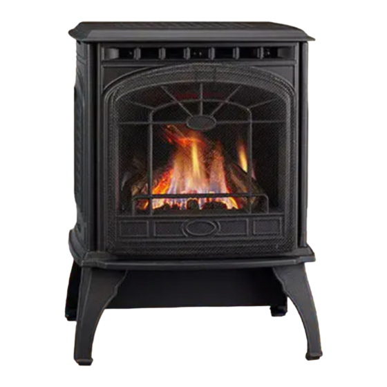
Garnet
DIRECT VENT ROOM HEATER
This appliance may be installed in an aftermar-
ket, permanently located, Manufactured (Mobile)
Home, where not prohibited by Local Codes.
This appliance is only for use with the type of fuel
indicated on the Rating Plate. This appliance is
not convertible for use with other gases, unless a
certified Conversion Kit is used.
1445 N. Highway
Colville, WA 99114-2008
Tested and
Listed by
OMNI-Test Laboratories, Inc.
WARNING!
Improper installation, adjustment, alteration, ser-
vice or maintenance can cause injury or property
damage. Refer to this Manual. For assistance or
additional information, consult a qualified installer,
service agency or the gas supplier.
This appliance may be installed as an OEM instal-
lation in manufactured home (USA only) or mobile
home and must be installed in accordance with the
manufacturer's instructions and the manufactured
home construction and safety standard, Title 24
CFR, Part 3280 or Standard for Installation in Mobile
Homes, CAN/CSA Z240 MH.
This appliance is only for use with the type(s) of
gas indicated on the rating plate. A conversion kit
is supplied with the appliance.
This Heater may be installed with a Vertical
or Horizontal Direct Vent Termination System.
R
Beaverton
O-T L
Oregon USA
C
SAVE THESE
INSTRUCTIONS
www.quadrafire.com
Advertisement
Table of Contents

Related Manuals for Quadra-Fire Garnet


Summary of Contents for Quadra-Fire Garnet
- Page 1 A conversion kit is supplied with the appliance. This Manual must be used for installation of the Garnet Gas-Fired Room Heater and retained This Heater may be installed with a Vertical by the homeowner for operating and maintenance or Horizontal Direct Vent Termination System.
- Page 2 Ask your Quadra-Fire Dealer for information on these options. From design, to fabrication, to shipping: Our guarantee of quality is more than a word, it’s Quadra-Fire tradition, and we proudly back this tradition with a Lifetime Warranty.
-
Page 3: Table Of Contents
GARNET DIRECT VENT ROOM HEATER GARNET DIRECT VENT ROOM HEATER PLEASE RETAIN THIS MANUAL FOR FUTURE REFERENCE. TABLE OF CONTENTS Listings and Code Approvals..........4 Model Name: Model Name: Specifications..............4 Notices ................4 Safety Notices..............5 GARNET DIRECT VENT ROOM HEATER Dovre Garnet DV250 Overview of Installation ............ -
Page 4: Listings And Code Approvals
National Electrical Code, ANSI/NFPA 70, or the Canadian Electrical Code, CSA C22.1. The Garnet is manufactured to operate on Natural Gas (NG), it is field convertible to Liquid Propane (LP) using the manufacturer's conversion kit. -
Page 5: Safety Notices
GARNET DIRECT VENT ROOM HEATER SAFETY NOTICES Due to high temperatures, the appliance should be located Do not operate with glass cracked or broken. out of traffic and away from furniture and draperies. This unit is not for use with solid fuel. -
Page 6: Overview Of Installation
GARNET DIRECT VENT ROOM HEATER OVERVIEW OF INSTALLATION TO OPERATION • Familiarize yourself with this Owner's Manual and the Safety Notices located in this manual, and posted on the gas appliance. • Remove and unpack the following components: The Log Set is taped to the top of the stove. -
Page 7: Dimensions
GARNET DIRECT VENT ROOM HEATER DIMENSIONS NOTE: Diagrams show gas stove equipped with optional Blower, Part #844-9370. CLEARANCES TO COMBUSTIBLES Minimum clearances required from combustible construction for all appliance surfaces HEARTH: A non-combustible hearth pad is not required. However, the floor beneath the stove must be stable, 3 1/2"... -
Page 8: Lp Gas Conversion Instructions
GARNET DIRECT VENT ROOM HEATER LP CONVERSION INSTRUCTIONS TOOLS REQUIRED: Power drill (a 90° handle is NOTE: Have the gas supply line installed in accordance with local building codes by a qualified installer helpful) or slotted screwdriver or Torx TH20; #2 approved and/or licensed as required by the locality. -
Page 9: Thermostat Installation/Remote Control
GARNET DIRECT VENT ROOM HEATER THERMOSTAT INSTALLATION A thermostat may be installed to regulate the Garnet. It is important to use a thermostat designed for millivolt operation. Do not connect the heater to a thermostat serving any other appliance. Bedroom installation in Canada requires this heater to be connected to a thermostat. -
Page 10: Log Set Installation
Left Twig Fig. 2 PLEASE NOTE: Logs have been designed to work Right Twig Fig. 3 specifically with the burner of the Garnet. Exact Lava Rock Fig. 4 placement will ensure proper operation of your gas Installation: appliance and reduce sooting. -
Page 11: Blower Kit Installation Instruction
GARNET DIRECT VENT ROOM HEATER BLOWER INSTALLATION PART #844-9370 KIT CONTENTS: Blower motor, housing and snap disc assembly; rheostat (speed control); rheostat nut; knob; screws; knob position label. TOOLS REQUIRED: Short #2 Philips head screwdriver; 11/16" wrench. The blower is held in place using 4-#6 screws. The scews are already installed in the bottom of the fire box. -
Page 12: General Venting Instructions
FIELD-FABRICATED VENTING COMPONENTS. The hazards may result from any of the following actions: Garnet is approved to be vented either horizontally, Installation of any damaged venting component, through the side wall, or vertically, through the roof. -
Page 13: Installation Methods & Notes
Four types of direct vent system installations are each floor level. If an offset is needed in the attic, approved for use with the Garnet. additional pipe and elbows will be required. When determining the position of the stove, be sure to 1. -
Page 14: Simpson-Duravent And Hti Parts List
SECURITY CHIMNEY'S SECURE VENT CHIMNEY SYSTEM & AMERIVENT DIRECT VENTING COMPONENTS Your Quadra-Fire Garnet has been approved with Security Chimney's Secure Vent Chimney System and Amerivent Direct Venting Components. All the required certification tests have been successfully completed with OMNI-Test Laboratories, Inc. -
Page 15: Installation Methods
GARNET DIRECT VENT ROOM HEATER INSTALLATION METHODS FIG. 1 - HORIZONTAL TERMINATION Refer to pages 20-22 for installation instructions and requirements. Type A - Up & Out Installation 90 DEG. ELBOW center line PIPE LENGTH HTI Vent HHW2 Part #841-0670... - Page 16 GARNET DIRECT VENT ROOM HEATER SLIM LINE WALL THIMBLE Part #844-9550 Fig. 1 Solid Trim Ring Shown BEFORE YOU BEGIN: Venting configuration will determine which Trim Ring you use in your installation. Review Figures A, B and C on Page 17. Figures A and B can use either Trim Ring, while Figure C REQUIRES the Ventilated Trim Ring.
-
Page 17: Fig. 5
GARNET DIRECT VENT ROOM HEATER SLIM LINE WALL THIMBLE (cont'd.) FIG. A 90 DEGREE ELBOW Note: When installing the Garnet to a rear wall in the Zero Clearance configuration Use HEAT SHIELD or WALL THIMBLE remove the two heat shield knock-outs on... - Page 18 GARNET DIRECT VENT ROOM HEATER INSTALLATION METHODS (cont'd.) FIG. 3 - CLASS A METAL CHIMNEY FIG. 2 - VERTICAL TERMINATION (USA only) Refer to pages 25-27 for installation instructions and requirements. Refer to page 29 for installation instructions and requirements.
- Page 19 GARNET DIRECT VENT ROOM HEATER INSTALLATION METHODS (cont'd.) FIG. 4 - A, B C & D INTO A MASONRY CHIMNEY (USA only) Refer to pages 30-32 for installation instructions and requirements. Type A & B Co-Axial to Co-Linear Part 923GCL Type C - Up &...
-
Page 20: Termination Requirements
GARNET DIRECT VENT ROOM HEATER HORIZONTAL TERMINATION REQUIREMENTS A = 12" clearances above grade, veranda, porch, deck or balcony B = 12" clearances to window or door that may be opened C = 12" USA/12" Canada: clearance to permanently closed window *D = 18"... -
Page 21: Horizontal Installation
GARNET DIRECT VENT ROOM HEATER HORIZONTAL INSTALLATION Step 1. Step 3. Determine the desired location of the stove. Check to For installations using a Wall Thimble Dura-Vent Part #942, ensure that wall studs or roof rafters are not in the way mark the wall for a 10”... - Page 22 GARNET DIRECT VENT ROOM HEATER HORIZONTAL INSTALLATION (cont'd.) Step 4. Position the horizontal vent termination in the center of the 10" x 10" (25.4cm x 25.4cm) square hole and run a bead of non-hardening mastic around its outside edges, so as to make a seal between it and the wall, attach termination cap to the exterior wall with the four wood screws provided.
-
Page 23: Vent Graph
GARNET DIRECT VENT ROOM HEATER INSTALLATION VENT GRAPH Measure the vertical distance from the center line of the flue pipe to the center of the 90° elbow. On the graph below, draw a horizontal line from that measurement on the vertical axis across until it intersects with the slanted line. -
Page 24: Vertical Damper Adjustment/Flue Restrictor
GARNET DIRECT VENT ROOM HEATER DAMPER INSTALLATION AND ADJUSTMENT WHEN YOUR INSTALLATION FALLS WITHIN A SHADED AREA ON THE VENT GRAPH (PAGE 23). A DAMPER MUST BE INSTALLED FOR PROPER OPERATION. (In the Commonwealth of Massachusetts, the word damper shall be replaced with the words flue restrictor.) Installation of the damper requires the removal of the baffle. -
Page 25: Vertical Installation
GARNET DIRECT VENT ROOM HEATER VERTICAL INSTALLATION INSTRUCTIONS USING GS SERIES PIPE Step 1. Check the installation instructions for required 1” (25mm) clearances (air space) to combustibles when passing through ceilings, walls, roofs, enclosures, attic rafters, or other nearby combustible surfaces. See page 27, Fig. 16. Do not pack air space with insulation. - Page 26 GARNET DIRECT VENT ROOM HEATER VERTICAL INSTALLATION USING GS SERIES PIPE (cont'd.) Step 2. of pipe and elbows necessary to reach from the ceiling et the gas stove in its desired location. Drop a plumb bob support box up through the roof line. Galvanized pipe...
-
Page 27: Roof Pitch Table
GARNET DIRECT VENT ROOM HEATER VERTICAL INSTALLATION USING GS SERIES PIPE (cont'd.) Step 7. Step 8. Continue to assemble pipe sections until the height Twist-lock the vent cap and seal. of the vent cap (H) (Fig. 15) meets the minimum... -
Page 28: Cathedral Ceiling Installation
GARNET DIRECT VENT ROOM HEATER VERTICAL INSTALLATION CATHEDRAL CEILING INSTALLATION Step 1. Follow installation Steps 1 and 2 under vertical termination section, pages 25 and 26. FIG. 17 LEVEL Step 2. Using the plumb-bob, mark the centerline of the CATHEDRAL CEILING... -
Page 29: Class A Metal Chimney
GARNET DIRECT VENT ROOM HEATER VERTICAL INSTALLATION INSTALLATION INTO A CLASS A METAL CHIMNEY (USA ONLY) NOTE: Have the existing installation inspected by Step 4. a qualified chimney sweep or professional installer Pass the flex pipe down through the center of the prior to converting to direct vent. -
Page 30: Existing Masonry Chimey
GARNET DIRECT VENT ROOM HEATER VERTICAL INSTALLATION INSTALLATION INTO AN EXISTING MASONRY CHIMNEY (USA ONLY) Step 1. Step 3. Before cutting any holes, assemble the desired sections Secure the flashing (SDV of direct vent pipe to determine the center of the masonry #705C) to the top of the FIG. - Page 31 GARNET DIRECT VENT ROOM HEATER VERTICAL INSTALLATION INSTALLATION INTO AN EXISTING MASONRY CHIMNEY (USA ONLY) (cont'd.) FLEX LINER FIG. 24 Step 7. If additional lengths of flex liner are needed to span the chimney height, use a flex coupler to connect the pieces of flex liner together.
- Page 32 GARNET DIRECT VENT ROOM HEATER VERTICAL INSTALLATION INSTALLATION INTO AN EXISTING MASONRY CHIMNEY (USA ONLY) (cont'd.) Step 9. Attach the flex to the retro connector. Use three sheet 6" DIAMETER OPENING metal screws to attach the flex liner to the connector IN MASONRY WALL (Fig.
-
Page 33: Gas Line Requirements
GARNET DIRECT VENT ROOM HEATER GAS LINE REQUIREMENTS The gas line must be installed in accordance with all After running new gas line, or if a gas line has been local codes, if any (and Commonwealth of Massachusetts disconnected, purging of the gas line may be necessary. -
Page 34: Checking Gas Inlet Pressure
GARNET DIRECT VENT ROOM HEATER CHECKING GAS INLET PRESSURE Step 1. Turn "ON" all other gas appliances in the household, and; Step 2. Turn the fireplace burner “ON”. Step 3. Connect manometer to pressure tap on valve after opening it. -
Page 35: Lighting Instructions
GARNET DIRECT VENT ROOM HEATER LIGHTING INSTRUCTIONS FOR YOUR SAFETY READ BEFORE LIGHTING WARNING: If you do not follow these instructions exactly, a fire or explosion may result causing property damage, personal injury or loss of life A. This appliance has a pilot that must be lit manually. When lighting the pilot, follow these instructions exactly. -
Page 36: High Altitude Operation Adjustment
GARNET DIRECT VENT ROOM HEATER HIGH ALTITUDE OPERATION Remove front (if installed), glass, and logs (if In Canada, this unit is approved from 0 to 4500 feet installed.) above sea level. Installation of this stove at altitudes 2. Remove log/burner pan: First remove screws then above 4500 feet is subject to field test of the individual lift the side of pan vertically and pull out of firebox. -
Page 37: Operating Procedures
GARNET DIRECT VENT ROOM HEATER OPERATING PROCEDURES Read this entire manual prior to using the fireplace. Pay particular attention to the “Safety Precautions” section on page 5. Failure to follow the instructions may result in property damage, bodily injury, or even death. -
Page 38: Yearly Maintenance
GARNET DIRECT VENT ROOM HEATER YEARLY MAINTENANCE PROCEDURES WARNING! Failure to inspect and maintain the stove may lead to improper combustion and a potentially dangerous situation. The following procedures are recommended to be completed by a qualified agency once per year, preferably prior to the burning season. -
Page 39: Ignition Module And Battery Replacement
The Ignition Module (automatic-ignitor) is located on the left side of the stove. This module was incorporated into the design of the Garnet DV to facilitate "one hand" lighting of the stove. When the gas control knob is turned to the "Pilot"... -
Page 40: Electrical Schematic
GARNET DIRECT VENT ROOM HEATER ELECTRICAL SCHEMATICS PILOT ASSEMBLY Ignition Module TPTH Black ON/OFF Switch Black VALVE Thermal Disc Receptacle, Molex Fan Speed Control Plug, Molex 34" Power Cord 34" (110 VAC) Ground Strain Relief Bushing Fan Assembly 250-6443B October 7, 2003... -
Page 41: Troubleshooting
GARNET DIRECT VENT ROOM HEATER TROUBLE SHOOTING 3. Is Blower operational? (Check Fan Speed control, Pilot Will Not Light Pg. 37.) 1. Is gas shut-off valve turned on? Pilot Goes Out Once a Month or More 2. Is the valve control knob turned to “PILOT” (See Lighting 1. -
Page 42: Parts & Accessories & Explosed View Schematic
GARNET DIRECT VENT ROOM HEATER PARTS & ACCESSORIES PLEASE CONTACT YOUR DEALER TO ORDER REPLACEMENT PARTS Part Number DESCRIPTION 844-9370 Blower Assembly with Speed Control (Thermostat capability) 812-3760 Manual Thermostat 811-0520 Programmable Thermostat 841-0960 Remote Control, Smart Stat 841-0970 Remote Control, Smart Batt... -
Page 43: Exploded View
GARNET DIRECT VENT ROOM HEATER EXPLODED VIEW 250-6443B October 7, 2003 Page 43... -
Page 44: Warranty
GARNET DIRECT VENT ROOM HEATER Lifetime Warranty LIMITED LIFETIME WARRANTY The Hearth & Home Technologies limited Lifetime Warranty guarantees that the following components will work as designed for the lifetime of the stove or Hearth & Home Technologies will repair or replace them. These items include but are not...
Need help?
Do you have a question about the Garnet and is the answer not in the manual?
Questions and answers