Table of Contents
Advertisement
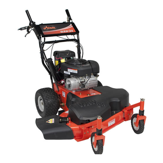
Wide Area Walk Mower
Owner/Operator Manual
Manuel du Propriétaire/Utilisateur
Gasoline containing up to 10% ethanol (E10) or up to 10% MTBE (methyl tertiary butyl ether) is
acceptable for use in this machine.
The use of any gasoline exceeding 10% ethanol (E10) or 10% MTBE will void the product warranty.
Il est possible d'utiliser de l'essence contenant jusqu'à 10% d'éthanol (E10) ou 10% de MTBE
(éther méthyl-tertiobutylique) sur cette machine.
L'utilisation d'une essence contenant plus de 10% d'éthanol (E10) ou de 10% de MTBE annulent la
garantie.
ENGLISH
FRENCH
Model
911413 – WAW 34
(Serial No. 013000 and up)
04081400B 4/12
Printed in USA
Advertisement
Table of Contents

Related Manuals for Ariens 911413–WAW 34


Summary of Contents for Ariens 911413–WAW 34
- Page 1 Wide Area Walk Mower Owner/Operator Manual Manuel du Propriétaire/Utilisateur Model 911413 – WAW 34 (Serial No. 013000 and up) Gasoline containing up to 10% ethanol (E10) or up to 10% MTBE (methyl tertiary butyl ether) is acceptable for use in this machine. The use of any gasoline exceeding 10% ethanol (E10) or 10% MTBE will void the product warranty.
-
Page 2: Table Of Contents
English may be obtained from completely read your manuals. The contents your Dealer. Visit your dealer or will give you an understanding of safety www.ariens.com. for a list of instructions and controls during normal languages available for your operation and maintenance. -
Page 3: Unauthorized Replacement Parts
Ariens authorized replacement part may adversely affect the performance, durability, or safety of this unit and may void the warranty. Ariens disclaims liability for any claims or damages, whether warranty, property damage, personal injury or death arising out of the use of unauthorized replacement parts. -
Page 4: Safety
SAFETY CAUTION: POTENTIALLY WARNING: This cutting machine HAZARDOUS SITUATION! If not is capable of amputating hands avoided, MAY RESULT in minor or and feet and throwing objects. moderate injury. It may also be Failure to observe the safety used to alert against unsafe instructions in the manuals and practices. - Page 5 SAFETY DECALS AND LOCATIONS ALWAYS replace missing or damaged safety decals. Refer to Figure 2 for safety decal locations. 05365900 07800404 KEEP HANDS and FEET AWAY Figure 2 1. DANGER! To avoid dismemberment hazard do not put hands near moving belts. DANGER! Keep hands away from all rotating or moving parts.
- Page 6 1.2 Discharge Hazard 2. DANGER! Discharge Hazard – Discharge Hazard – NEVER operate unit NEVER direct discharge without discharge chute in toward people, pets or operating position. Thrown property. Thrown objects objects can cause injury or can cause injury or damage.
-
Page 7: Safety Rules
5 seconds whenever components can only be adjusted by an operator releases PTO lever. Check this Ariens Company dealer or an authorized feature frequently. If feature fails to operate, engine manufacturer's service center. disconnect spark plug wire and adjust or have Contact your Ariens Company Equipment it repaired before using unit. - Page 8 Stop engine, must be maintained in effective working order remove key (electric start models) and wait by the operator. See your Ariens Dealer or for all moving parts to stop before servicing. engine manufacturer’s service center. DO NOT make cutting height wheel Fuel is highly flammable and its vapors are adjustments while the engine is running.
- Page 9 Contact with skin, eyes or clothing can cause Use only accessories which have been severe chemical burns. approved by Ariens and are properly ALWAYS wear safety glasses and protective installed. gear near battery. Use only accessories or attachments that are...
-
Page 10: Assembly
ASSEMBLY ASSEMBLY CAUTION: AVOID INJURY. Read 1. Remove all packing materials and straps and understand the entire Safety from unit. section before proceeding. 2. Remove lower pair of nuts and bolts from the handlebars. CARTON CONTENTS 3. Rotate the handlebar into the operating position. - Page 11 6. Check engine crankcase oil level. See engine manual. 7. Connect the battery ground cable (–) to the negative battery terminal. 8. Fill fuel tank. DO NOT OVERFILL! (See FILLING THE FUEL TANK on page 15). NOTE: After the first twenty-five hours of operation, belt wear may require the PTO clutch cable and the drive control cables to be adjusted.
-
Page 12: Controls And Features
CONTROLS AND FEATURES 05365400A Figure 6 1. PTO Clutch Lever 2. Parking Brake Release Lever 3. Forward Drive Control 4. Reverse Drive Control 5. Handlebars 6. Fuel Tank and Cap 7. Height Adjustment Spacers 8. Muffler 9. Oil Fill/Dipstick 10. Air Filter 11. -
Page 13: Operation
OPERATION CONTROLS AND FEATURES PTO Disengaged: Mower blades See Figure 6 for locations. stop rotating. WARNING: Improper operation can lead to injury. Learn what the controls do and how they work. Thoroughly read and understand entire Operator Manual. PTO Engaged: Hold down the lock lever and then hold clutch lever CAUTION: AVOID INJURY. - Page 14 Lock Pin Remove the spacers from the stack. Flats Spacers Secure spacers above the Figure 7 caster arm with the lock pin. Align the open ends of the spacers with the flats on the caster spindle and remove the spacers one at a time until enough are left at the bottom for the desired cutting height.
-
Page 15: Filling The Fuel Tank
Forward Drive Control (Lower Right Hand Control) Reverse Drive Control CAUTION: Unit will move at engine start if the wheel drive controls are engaged. ALWAYS release the wheel drive controls before starting unit. STOP NOTE: Engine must be running for wheel drive to propel unit. -
Page 16: Electric Start
GASOLINE To stop the mower in an emergency: 1. Release the PTO clutch lever and the IMPORTANT: ALWAYS use gasoline that parking brake lever. meets the following guidelines: 2. Turn the ignition key to the "OFF" • Clean, fresh gasoline. position. -
Page 17: Maintenance
5 seconds after releasing the control. If the blade continues to run, adjust or repair Ariens Dealers will provide any service, parts control immediately. or adjustments which may be required to keep your unit operating at peak efficiency. - Page 18 To install blade: DO NOT Sharpen to This Pattern 1. Install mower blades on mower deck with mounting hardware. 2. Torque 5/8-inch nut to 92 to 130 lbf-ft (125 to 176 N•m). 3. Connect spark plug wire. DISCARD If More Than 1/2 in.
-
Page 19: Check Spark Plug
CHECK DRIVE BELTS CHECK SPARK PLUG Check drive belts and replace if worn or Spark plug should be replaced every 100 damaged. See Wheel Drive Belts on page 21. hours of operation or each year. NOTE: Loose spark plug wire terminals can CHECK FASTENERS cause sparking. -
Page 20: Service And Adjustments
4. Tighten the lock nut to hold the adjustment. IMPORTANT: If you cannot adjust the PTO clutch or if it fails to operate properly, immediately take the unit to your Ariens dealer for repair. 1. Cable 2. Lock Nut Adjuster Figure 13 1. -
Page 21: Belt Replacement
BELT REPLACEMENT NOTE: Check the wheel drive control adjustment after the first 25 hours of use to compensate for belt wear. WARNING: AVOID INJURY. ALWAYS block wheels, engage Rear of Unit – Forward Drive Belt Routing parking brake and know all jack stands are strong, secure and will hold weight of unit during maintenance. -
Page 22: Deck Belt
PTO Belt Deck Belt 1. Stop engine, remove key, wait for all 1. Stop engine, remove key, wait for all moving parts to stop and hot parts to moving parts to stop and hot parts to cool. cool. 2. Remove the two drive belts from engine 2. -
Page 23: Servicing The Battery
SERVICING THE BATTERY NOTE: Unit comes equipped with a maintenance-free battery that requires no regular maintenance except cleaning the terminals. NOTE: Unit may be equipped with a U1 style battery and cover or a sealed glass mat battery with boot terminal. WARNING: Battery posts, terminals and related accessories contain lead and lead... - Page 24 Sealed Glass Mat Battery Removal Replacing Sealed Glass Mat Battery and Installation (Figure 19) with U1-Size Battery (Figure 19 and Figure 20) NOTE: If same size replacement battery is not available a U1-size battery can be 1. Disconnect negative (–) cable first, then installed (see Figure 21).
-
Page 25: Charging The Battery
5. Install battery on unit. 1. Remove the battery cover (if equipped). Jump-Starting 2. Disconnect negative (–) cable first, then Ariens does not recommend jump-starting positive (+) cable. your unit. Jump-starting can damage engine 3. Clean battery cable ends, negative (–) and electrical system components. -
Page 26: Storage
Follow the to prevent rust. Matching touch-up paint is recommended mix ratio found on the fuel available from your Ariens Dealer. Do not use stabilizer container. abrasives, solvents, or harsh cleaners. To treat the fuel system for storage: Inspection 1. -
Page 27: Service Parts
3. Damaged transmission or 3. See your authorized dealer drive component. for repairs. SERVICE PARTS ACCESSORIES Always use genuine Ariens parts to keep See your authorized Ariens Dealer to add your mower running like new. these optional accessories. Part Description... -
Page 28: Specifications
SPECIFICATIONS Model Number 911413 Description WAW 34 Length – in. (cm) 68.5 (174) Height – in. (cm) 38 (96.5) Width – in. (cm) 36 (91.4) Actual Weight – lbs (kg) 276 (125.2) Cutting Width – in. (cm) 34 (86.3) Cutting Height – in. (cm) 1.75 –... -
Page 29: Warranty
Register the product immediately at the time of sale. If the dealer does not register the product, the customer must complete the product registration card in the literature package and return it to the Ariens Company, or register the unit online at www.ariens.com, www.gravely.com, www.countax.com. - Page 30 Exclusions – Items Not Covered by This Warranty • Parts that are not genuine Ariens, Gravely or Countax service parts are not covered by this warranty and may void the warranty. • Damages resulting from the installation or use of any part, accessory, or attachment which is not approved by the Ariens Company for use with product(s) identified herein are not covered by this warranty.
Need help?
Do you have a question about the 911413–WAW 34 and is the answer not in the manual?
Questions and answers
If you raise the front of the deck won’t that mess up the front to back angle?
Yes, raising the front of the deck on the Ariens model 911413–WAW 34 will affect the front-to-back angle (deck pitch). Deck pitch refers to the angle of the mower deck relative to the ground. Adjusting the front height changes this angle, which can impact cutting performance and grass discharge.
This answer is automatically generated