Table of Contents
Advertisement
Advertisement
Table of Contents

Related Manuals for Delta 28-195


Summary of Contents for Delta 28-195
- Page 1 10" Band Saw (Model 28-195) PART NO. 902127 (0112) Copyright © 2001 Delta Machinery To learn more about DELTA MACHINERY ESPAÑOL: PÁGINA 23 visit our website at: www.deltamachinery.com. For Parts, Service, Warranty or other Assistance, 1-800-223-7278 ( 1-800-463-3582). please call...
-
Page 2: General Safety Rules
If you have any questions relative to a particular application, DO NOT use the machine until you have first contacted Delta to determine if it can or should be performed on the product. -
Page 3: Save These Instructions
ADDITIONAL SAFETY RULES FOR BAND SAWS WARNING: FAILURE TO FOLLOW THESE RULES MAY RESULT IN SERIOUS PERSONAL INJURY. 14. NEVER REACH UNDER THE TABLE while the DO NOT OPERATE THIS MACHINE UNTIL it is machine is running. assembled and installed according to the instructions. -
Page 4: Power Connections
POWER CONNECTIONS A separate electrical circuit should be used for your machines. This circuit should not be less than #12 wire and should be protected with a 20 Amp time lag fuse. If an extension cord is used, use only 3-wire extension cords which have 3- prong grounding type plugs and matching receptacle which will accept the machine’s plug. -
Page 5: Extension Cords
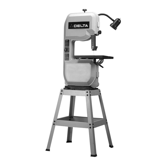
FOREWORD Delta Model 28-195 is a 10" Band Saw. The Delta Model 28-195 has a powerful 1/2 HP, ball-bearing motor for smooth performance and longer life. The 28-195 is supplied with a sturdy steel stand which provides heavy-duty support and a comfortable work height. - Page 6 Fig. 2 For Fig. 2 For mounting lamp to machine 1 - Band Saw 10 - M6 x 12mm sheet metal screw (2) 2 - Table 11. - M6 lockwasher (2) 3 - Miter Gage For aligning table 4 - Table Insert 12 - M6 x 30mm button head bolt (1) For mounting machine to stand 13 - M6 flat washer (1)
- Page 7 Fig. 3 For Fig. 3 1 - Stand legs (4) 2 - Upper braces for stand (2), 10-3/4" 3 - Upper braces for stand (2), 13-9/16" 4 - Lower braces for stand (2), 15-3/4 " 5 - Lower braces for stand (2), 18-5/16" 6 - Feet (4), 7 - M8 x 20mm carriage bolts (32) 8 - 3/8 flat washers (32)
-
Page 8: Stand
ASSEMBLY INSTRUCTIONS WARNING: FOR YOUR OWN SAFETY, DO NOT CONNECT THE MACHINE TO THE POWER SOURCE UNTIL THE MACHINE IS COMPLETELY ASSEMBLED AND YOU READ AND UNDERSTAND THE ENTIRE OWNER’S MANUAL. ASSEMBLING STAND AND FEET 1. Assemble the stand, as shown in Fig. 4, using the 32 M8x20mm Carriage head screws, 3/8"... -
Page 9: Assembling Table Insert
ASSEMBLING TABLE TO MACHINE 1. Slide table (A) Fig. 7, into position on band saw trunnions, as shown. Fig. 7 2. Line up the four threaded holes in bottom of table with four holes in table trunnions (B) Fig. 8, and fasten the table to the trunnions using the four M6 x 16mm hex head bolts (C) and M6 flat washers (A), three of which are shown. -
Page 10: M6 X 30Mm Button Head
ASSEMBLING TABLE ALIGNMENT SCREW Insert M6 x 30mm button head bolt (A) Fig. 11, down through hole in table, as shown, and place a M6 flat washer (C) onto bolt from underneath table and fasten in place with an M6 wing nut (B). Fig. -
Page 11: Adjusting Blade Tension
OPERATING CONTROLS AND ADJUSTMENTS STARTING AND STOPPING SAW The switch (A) Fig. 17, is located on the front side of the band saw. To turn the saw “ON” move the switch (A) to the up position.To turn the saw “OFF” move the switch (A) to the down position. -
Page 12: Tracking The Blade
TRACKING THE BLADE For accurate work and maximum blade life, it is important that the blade (A) Fig. 20, be centered on the upper band saw wheel. When this adjustment is properly made, the blade will “track” – that is, it will run steady in the same line. To “track”... -
Page 13: Adjusting Upper Blade Guides And Blade Support Bearing
ADJUSTING UPPER BLADE GUIDES AND BLADE SUPPORT BEARING The blade guides must be properly adjusted to prevent the blade from twisting during operation. The upper blade guides and blade support bearings should be adjusted only after the blade is tensioned and tracking properly. To adjust, proceed as follows: 1. -
Page 14: Adjusting Lower Blade Guides And Blade Support Bearing
ADJUSTING LOWER BLADE GUIDES AND BLADE SUPPORT BEARING The lower blade guides and blade support bearing should be adjusted at the same time as the upper guides and support bearing as follows: 1. DISCONNECT MACHINE FROM POWER SOURCE. Fig. 25 Fig. -
Page 15: Tilting The Table
TILTING THE TABLE The table can be tilted 48 degrees to the right and approximately 3 degrees to the left. To tilt the table, loosen lock handle (A) Fig. 27, tilt the table to the desired angle and tighten lock handle (A). NOTE: The table lock handle (A) can be repositioned by pulling out on the handle and repositioning it on the nut located underneath the hub of the handle. -
Page 16: Adjusting Upper Blade Guide Assembly
ADJUSTING UPPER BLADE GUIDE ASSEMBLY The upper blade guide assembly (A) Fig. 31, should always be set about 1/8 above or as close as possible to the top surface of the workpiece being cut. Loosen lock knob (B) and rotate adjusting knob (C) to position the guide assembly (A) at the desired height. -
Page 17: Adjusting Belt Tension
MINIMUM CUTTING RADIUS Turning radius may vary depending on the type of blade and amount of set. Each blade, however, depending on its width, can cut continuously without backtracking any curve having a radius as much or more than the specified minimum turning radius of the blade, as shown in the chart (A) Fig. -
Page 18: Wrench Storage
WRENCH STORAGE The hex wrench (A) supplied with your band saw can be stored inside the wheel cover, as shown in Fig. 39. Fig. 39 DUST CHUTE A dust chute (A) Fig. 40, is provided which enables you to connect your band saw to a standard shop vacuum or dust collector. -
Page 19: Cutting Curves
This will save blades and will produce better work. Band saw blades may be purchased, welded, set and sharpened ready for use. For cutting wood and similar materials, Delta can supply blades in widths of 1/8, 1/4, 3/8, and 1/2 inches. - Page 20 Two Year Limited Warranty Delta will repair or replace, at its expense and at its option, any Delta machine, machine part, or machine accessory which in normal use has proven to be defective in workmanship or material, provided that the customer returns the product prepaid to a Delta factory service center or authorized service station with proof of purchase of the product within two years and provides Delta with reasonable opportunity to verify the alleged defect by inspection.
- Page 21 Delta Distributor, Authorized · Service Center, or Porter-Cable Delta Factory Service Center. If you do not have access to any of these, call 800-223-7278 and you will · be directed to the nearest Porter-Cable Delta Factory Service Center. Las Estaciones de Servicio Autorizadas están ubicadas en muchas grandes ciudades.
Need help?
Do you have a question about the 28-195 and is the answer not in the manual?
Questions and answers