Table of Contents
Advertisement
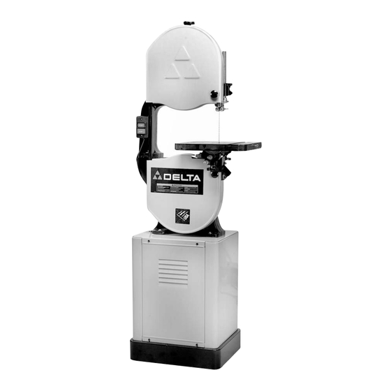
14" Wood Cutting
Band Saw
(Models 28-241 & 28-299A)
426-02-651-0049 - 06-24-02
Copyright © 2002 Delta Machinery
To learn more about DELTA MACHINERY
visit our website at: www.deltamachinery.com.
For Parts, Service, Warranty or other Assistance,
1-800-223-7278 (
1-800-463-3582).
please call
In Canada call
Advertisement
Table of Contents

Related Manuals for Delta 28-241


Summary of Contents for Delta 28-241
- Page 1 14" Wood Cutting Band Saw (Models 28-241 & 28-299A) 426-02-651-0049 - 06-24-02 Copyright © 2002 Delta Machinery To learn more about DELTA MACHINERY visit our website at: www.deltamachinery.com. For Parts, Service, Warranty or other Assistance, 1-800-223-7278 ( 1-800-463-3582). please call...
-
Page 2: General Safety Rules
If you have any questions rela- tive to a particular application, DO NOT use the machine until you have first contacted Delta to determine if it can or should be performed on the product. -
Page 3: Additional Safety Rules For Band Saws
ADDITIONAL SAFETY RULES FOR BAND SAWS WARNING: FAILURE TO FOLLOW THESE RULES MAY RESULT IN SERIOUS PERSONAL INJURY. DO NOT OPERATE THIS MACHINE UNTIL it is 15. TURN THE MACHINE “OFF” to back out of an assembled and installed according to the instruc- uncompleted or jammed cut. -
Page 4: Motor Specifications
POWER CONNECTIONS A separate electrical circuit should be used for your machines. This circuit should not be less than #12 wire and should be protected with a 20 Amp time lag fuse. If an extension cord is used, use only 3-wire extension cords which have 3- prong grounding type plugs and matching receptacle which will accept the machine’s plug. -
Page 5: Extension Cords
FOREWORD Delta Models 28-241 and 28-299A are 14" Band Saws, equipped with a 1-1/2 HP, 120V guarded, drip-proof motor inside an enclosed stand. Included with each saw is a push button switch, a blade and belt guard, an arbor and motor pulleys with a V- belt, blade guides, a wood cutting blade, and an instruction manual. - Page 6 ASSEMBLY STAND The stand is shipped top-down in the shipping container with the motor mounted to the inside top of the stand. The on/off switch is wired to the end of the power cord. To make the motor operational, do the following: Remove the stand (A) Fig.
- Page 7 ATTACHING BAND SAW TO THE STAND CAUTION: The band saw is very heavy. Use a helper when attaching the saw to the stand. Attach the band saw to the stand by using the four holes provided (two of which are shown at (A) Fig. 8). Place one 5/16-18 x 1-3/4"...
-
Page 8: Starting And Stopping Saw
Fig. 15 Fig. 14 5. Use the two nuts and lockwashers (E) Fig. 14, removed in STEP 3, to fasten the switch box to the bandsaw arm (Fig. 14). 6. Remove the screw (F) and cable clamp (E) Fig. 15 from the lower arm of the band saw. -
Page 9: Adjusting Blade Tension
TILTING THE TABLE The table on the band saw can be tilted 45 degrees to the right and 10 degrees to the left. To tilt the table to the right, loosen the two locking knobs (A) Fig. 20, tilt the table to the desired angle as shown on the scale (D) Figs. -
Page 10: Tracking The Blade
Fig. 25 Fig. 24 TRACKING THE BLADE CAUTION: DISCONNECT TOOL FROM POWER SOURCE. IMPORTANT: Before tracking the blade, make sure that the blade guides and blade support bearings are clear of the blade. After applying tension to the blade, rotate the wheels slowly forward by hand and observe the blade’s movement. The blade (A) Fig. -
Page 11: Changing The Blades
Fig. 27 Fig. 28 ADJUSTING LOWER BLADE GUIDES AND BLADE SUPPORT BEARING Adjust the lower blade guides and blade support bearing after the the upper guides and bearing have been adjusted. 1. DISCONNECT TOOL FROM POWER SOURCE. 2. Adjust the front edge of the guide blocks (B) Fig. 27 so that they are just behind the “gullets”... -
Page 12: Band Saw Blades
BAND SAW BLADES A bandsaw blade is a delicate piece of steel that is subjected to a great deal of stress. Proper blade care results in optimal performance. Always use blades of the proper thickness, width, and temper to correspond to the workpiece. Use the widest blade possible. - Page 13 ACCESSORIES A complete line of accessories is available from your Delta Supplier, Porter-Cable • Delta Factory Service Centers, www.deltamachinery.com and Delta Authorized Service Stations. Please visit our Web Site for a catalog or for the name of your nearest supplier.
-
Page 14: Parts, Service Or Warranty Assistance
Two Year Limited Warranty Delta will repair or replace, at its expense and at its option, any Delta machine, machine part, or machine accessory which in normal use has proven to be defective in workmanship or material, provided that the customer returns the product pre- paid to a Delta factory service center or authorized service station with proof of purchase of the product within two years and provides Delta with reasonable opportunity to verify the alleged defect by inspection. - Page 15 NOTES...
- Page 16 Delta Distributor, Authorized · Service Center, or Porter-Cable Delta Factory Service Center. If you do not have access to any of these, call 800-223-7278 and you will · be directed to the nearest Porter-Cable Delta Factory Service Center. Las Estaciones de Servicio Autorizadas están ubicadas en muchas grandes ciudades.
Need help?
Do you have a question about the 28-241 and is the answer not in the manual?
Questions and answers