Table of Contents
Advertisement
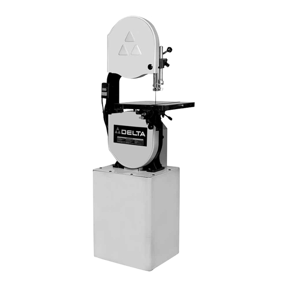
14" Wood Cutting Band Saw
(Model 28-248)
(Model 28-475X)
PART NO. 426-02-651-0055 - 08-26-05 - Rev. A
Copyright © 2005 Delta Machinery
To learn more about DELTA MACHINERY
visit our website at: www.deltamachinery.com.
For Parts, Service, Warranty or other Assistance,
1-800-223-7278 (
1-800-463-3582).
please call
In Canada call
Advertisement
Table of Contents


Need help?
Do you have a question about the SHOPMASTER 28-248 and is the answer not in the manual?
Questions and answers