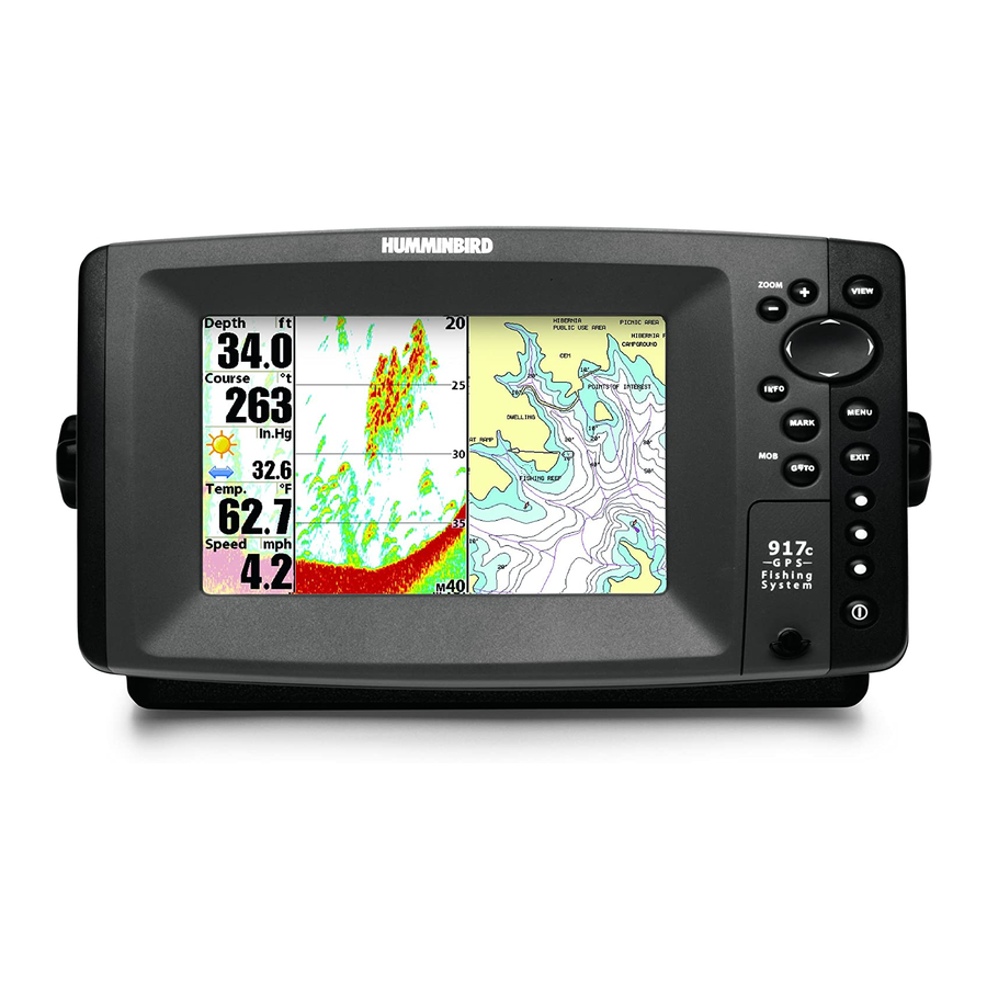
Humminbird 917C Installation And Operation Manual
Humminbird installation and operation manual gps receiver 917c, 957c
Hide thumbs
Also See for 917C:
- Compatibility listing (1 page) ,
- Installation and operation manual (141 pages)
Table of Contents
Advertisement
Quick Links
Advertisement
Table of Contents

Subscribe to Our Youtube Channel
Related Manuals for Humminbird 917C


![Fish Finder Humminbird ] 981 Installation & Operation Manual](https://static-data2.manualslib.com/product-images/915/73546/60x60/humminbird-981-fish-finder.jpg)


Summary of Contents for Humminbird 917C
-
Page 2: Thank You
Your Humminbird® is designed for trouble-free use in even the harshest marine environment. In the unlikely event that your Humminbird® does require repairs, we offer an exclusive Service Policy - free of charge during the first year after purchase, and available at a reasonable rate after the one-year period. -
Page 3: Table Of Contents
How Sonar Works ... 1 DualBeam PLUS™ Sonar ... 2 QuadraBeam PLUS™ Sonar (Standard with 957c Combo models, optional-purchase for 917c Combo models only) ... Universal Sonar 2 ... 3 How GPS and Cartography Work ... 3 Multi-Media Card (MMC)/SD Slot... 5 Software Updates ... - Page 4 Table of Contents Views Views and Readouts... 37 Sonar View ... 38 Sonar Zoom View ... 39 Split Sonar View ... 40 Snapshot and Recording View... 41 Side Beam View (with QuadraBeam PLUS™ only) Bird’s Eye View ... 47 Chart/Bird’s Eye Combo View ... 48 Chart/Chart Combo View ...
- Page 5 Table of Contents Navigation X-Press™ Menu Active Side... 70 Split Position ... 70 Waypoint [Name] (Only with an active cursor on a waypoint) ... Cursor to Waypoint (Chart or Combo view only) ... Save Current Track ... 72 Clear Current Track ... 72 Save Current Route ...
- Page 6 Table of Contents Navigation Menu Tab Current Track ... 88 Saved Tracks ... 88 Waypoints ... 89 Routes ... 89 Chart Orientation ... 90 North Reference ... 90 Trolling Grid Rotation ... 91 Trackpoint Interval... 91 Track Min Distance ... 91 (Advanced) Track Color Range...
- Page 7 NOTE: Entries in this Table of Contents which list (with Speed Input) or (with Temperature Input) may require the purchase of separate accessories. You can visit our website at www.humminbird.com to order these accessories online or contact our Customer Resource Center at 1-800-633-1468.
-
Page 9: 900 Series™ Introduction
See the following list of products, all of which are covered by this manual, to find your 900 Series™ configuration: • Humminbird® 917c Combo: Ultra Wide Screen Fishing System with Chartplotter (Maps) and DualBeam PLUS™ 200/83 kHz Transducer, GPS Receiver included •... -
Page 10: Dualbeam Plus™ Sonar
The sound pulses are transmitted at various frequencies depending on the application. Very high frequencies (455 kHz) are used for greatest definition but the operating depth is limited. High frequencies (200 kHz) are commonly used on consumer sonar and provide a good balance between depth performance and resolution. -
Page 11: Quadrabeam Plus™ Sonar
QuadraBeam PLUS™ Sonar (Standard with 957c Combo models, optional- purchase for 917c Combo models only) Your 900 Series™ 957c Combo is shipped with a QuadraBeam PLUS™ transducer. QuadraBeam PLUS™ sonar provides an extremely wide (90°) area of coverage. QuadraBeam PLUS™... - Page 12 GPS uses a constellation of 24 satellites that continually send radio signals to the earth. Your present position is determined by receiving signals from up to 16 satellites and measuring the distance from the satellites. All satellites broadcast a uniquely coded signal once per second at exactly the same time.
-
Page 13: Multi-Media Card (Mmc)/Sd Slot
NOTE: Accessories to enable WeatherSense® and the SmartCast® Wireless Sonar Link require separate purchases. You can visit our website at www.humminbird.com or contact our Customer Resource Center at 1-800-633-1468 for additional details. Installation Overview Please read all instructions that are relevant for your configuration before beginning the installation process. -
Page 14: Control Head Installation
• Testing the complete installation and locking the transducer position. NOTE: Accessories may require a separate purchase. You can visit our website at www.humminbird.com to order these accessories online or contact our Customer Resource Center at 1-800-633-1468. Control Head Installation You have two choices for mounting your 900 Series™... -
Page 15: Gimbal Mounting The Control Head
Gimbal Mounting the Control Head If you are gimbal mounting the Humminbird® 900 Series™, you can pre- assemble the unit in order to plan the best mounting location. Washer Gimbal Knob Gimbal Bracket In addition to the hardware supplied with your control head, you will need a... - Page 16 Receiver and accessories. Make the required installations and then run the cables to your control head mounting location. Do not cut any cabling (except the power cable). If your cables are too short, extensions are available from your local dealer or online from www.humminbird.com. 8.5" 5"...
- Page 17 hole, then use it to mark the position of the two mounting screws. Remove the hole cover, drill the two mounting holes using a 9/64" bit. Do not install the hole cover at this time. 6b. If the cables cannot be routed directly beneath the mounting bracket, mark and drill a 1"...
- Page 18 Cables Routed Behind Mounting Bracket Gimbal Bracket Grommet Hole Cover 9. Insert cable connectors into the proper recesses on the cable collector insert. The cable connectors are keyed to prevent reverse installation, so be careful not to force the connectors into the wrong slots.
-
Page 19: Connecting The Control Head Power Cable To The Boat
NOTE: You may wish to dress the cabling with nylon wire ties in order to hold the cables together and create a cleaner assembly. The Humminbird® 900 Series™ control head is now ready for operation. Connecting the Control Head Power Cable to the Boat A 6' (2 m) long power cable is included to supply power to the control head. -
Page 20: Transducer Installation
1b. If you need to wire the control head directly to a battery, obtain and install an inline fuse holder and a 3 amp fuse (not included) for the protection of the unit. Humminbird® is not responsible for overvoltage or over-current failures. -
Page 21: Transom Transducer Installation
Transom Transducer Installation If you will be installing a transom mounted transducer, use the procedures in this section. There are several procedures you will have to perform in order to install a transom-mounted transducer. They are: • Locate transducer mounting location •... - Page 22 NOTE: If you cannot find a transom mount location that will work for your high- speed application, find an In-Hull Transducer by contacting our Customer Resource Center at either 1-800-633-1468 or by visiting our website at www.humminbird.com. 2. Preparing the Mounting Location In this procedure, you will determine the mounting location and drill two mounting holes, using the transducer mounting bracket as a guide.
- Page 23 NOTE: If you have a flat-bottomed aluminum boat, some additional adjustment may be needed to accommodate the rivets on the bottom of the boat (i.e. the gap may need to be a little smaller than 1/8"). This will help you to avoid excessive turbulence at high speeds.
- Page 24 2. Place the two ratchets, one on either side of the transducer knuckle, so that the beads on each ratchet line up with the desired position number on the knuckle. If you are setting the ratchets at position 1, the beads on each ratchet will line up with the rib on the transducer knuckle to form one continuous line on the assembly.
- Page 25 Inserting the Pivot Arm Assembly Inserting the Pivot Bolt 3. Put the pivot bolt through the assembly to hold it in position and loosely install the nut, but do NOT tighten the nut at this time. Insert the pivot arm assembly into the mounting bracket. Do NOT snap the assembly closed, as you will need to access the mounting bracket in the next step.
- Page 26 Adjusting the Initial Transducer Angle Leading edge 7. Adjust the transducer assembly vertically, until the seam on the leading edge of the transducer (the edge closest to the transom of the boat) is level and just slightly below the hull. Adjusting the Transducer Mounting Position Seam aligned with boat hull...
- Page 27 50'. For assistance, contact the Customer Resource Center at www.humminbird.com or call 1-800-633-1468 for more information. NOTE: The transducer can pivot up to 90 degrees in the bracket. Allow enough slack in the cable for this movement.
- Page 28 2. If all connections are correct and power is available, the Humminbird® control head will enter Normal operation. 3. If the bottom is visible on-screen with a digital depth readout, the unit is working properly. Make sure that the boat is in water greater than 2' but less than the depth capability of the unit, and that the transducer is fully submerged, since the sonar signal cannot pass through air.
-
Page 29: Inside The Hull Transducer Installation
NOTE: The integral temperature probe will not work with in-hull mounting, so you may either want to consider purchasing a Temperature/Speed accessory, a Temp Sensor, or obtaining a different transducer. Humminbird® offers a transducer exchange program to swap the NEW and UNASSEMBLED transducer, accompanied by mounting hardware, for one without an integral temperature probe. - Page 30 1. Determine the transducer mounting location Decide where to install the transducer on the inside of the hull. Consider the following to find the best location: • Observe the outside of the boat hull to find the areas that are mostly free from turbulent water.
- Page 31 4. Fill the hull with enough water to submerge the transducer body. Use a sand-filled bag or other heavy object to hold the transducer in position. The transducer cannot transmit through air, and the water purges any air from between the transducer and the hull, and fills any voids in the coarse fiberglass surface.
-
Page 32: Trolling Motor Transducer Installation
NOTE: Proper operation requires the end of the transducer that has the mounting ears to face towards the bow of the boat. 7. Weight the transducer so that it will not move while the epoxy is curing. NOTE: When the epoxy cures, no water is necessary inside the hull. 8. -
Page 33: Trolling Motor Transducer Options
• Two control heads with one transducer • Two transducers with one control head. NOTE: Call the Humminbird® Customer Resource Center at 1-800-633-1468 for details and pricing, or visit www.humminbird.com for more information. GPS Receiver Installation To optimize performance of the GPS receiver, mount it in an area that has full exposure to the sky. -
Page 34: Stem Mounting With An Existing 1" - 14 Thread Stem
GPS receiver, follow the instructions included with that hardware to mount the stem (antenna pole). NOTE: AS-EC10 10' extension cables are available from Humminbird® if your planned routing exceeds 20', (6 m). Maximum cable length, including extensions, should not exceed 50' (16 m). -
Page 35: Access Under Mounting Location
1. Determine the best location, then test route the cable from the mounting location to the control head. NOTE: AS-EC10 10' extension cables are available from Humminbird® if your planned routing exceeds 20', (6 m). Maximum cable length, including extensions, should not exceed 50' (16 m). -
Page 36: Finish Routing The Cable And Check Gps Receiver Operation
3. The GPS receiver has two wire routing notches. Use the cable notch closest to the intended cable route. 4. With the cable routed, position the GPS receiver in the planned mounting location and mark the mounting holes with a pencil or punch. -
Page 37: Testing The System Installation
Testing the System Installation After you have completed the installation of the control head, transducer, and any other accessories such as the GPS receiver, and have made all the cabling connections required, you must test the installation before using the system. -
Page 38: Getting Started - Using Your 900 Series
Getting Started - Using Your 900 Series™ Your 900 Series™ Fishing System user interface is easy to use. A combination of keys, different views, and situation-specific, customizable menus allows you to control what you see on the color display. Refer to the following illustration, and see Key Functions, Views, and The Menu System) for more information. -
Page 39: What's On The Sonar Display
What’s On the Sonar Display The 900 Series™ can display a variety of useful information about the area under and adjacent to your boat, including the following items: Depth - water depth; can be set to alarm when the water becomes too shallow. Timer - Elapsed time with Speed accessory or GPS Receiver. -
Page 40: Understanding Sonar History
Understanding Sonar History It is important to understand the significance of the 900 Series™ display. The display does NOT show a literal 3-dimensional representation of what is under the water. Each vertical band of data received by the control head and plotted on the display represents something that was detected by a sonar return at a particular time. -
Page 41: Key Functions
WhiteLine® highlights the strongest sonar returns in white, resulting in a distinctive outline. This has the benefit of clearly defining the bottom on the display. Key Functions Your 900 Series™ user interface consists of a set of easy-to-use keys that work with various on-screen views and menus to give you flexibility and control over your fishing experience. -
Page 42: View Key
To adjust the backlight or to adjust the display background color, press the POWER/LIGHT key to access the Light and Background menu. Use the 4-WAY Cursor key to select Light or Background and then use the LEFT or RIGHT Cursor key to change the settings. -
Page 43: 4-Way Cursor Control Key
4-WAY Cursor Control Key The 4-WAY Cursor Control Key has multiple functions, depending on the situation: Freeze Frame - Pressing any arrow on the 4-WAY Cursor Control key will freeze the display in the Sonar View and a cursor and cursor dialog box will be displayed. -
Page 44: Info Key
INFO Key Press the INFO key while in any navigation view to display information about objects that are nearest to an active cursor. If the cursor is not active, the following menu will be displayed. Use the 4-WAY Cursor Control key to select Nearest Port, Nearest Tide Station or Nearest Current Station, then use the RIGHT Cursor key to display the requested information. -
Page 45: Zoom (+/-) Keys
ZOOM (+/-) Keys Press the - or + ZOOM keys while in any of the Navigation Views or the Sonar Zoom View to change the scale of the view to appear closer or farther away. Views The views available on your 900 Series™ are: Sonar Sonar View... -
Page 46: Sonar View
Sonar View Sonar View presents a historical log of sonar returns. The most recent sonar returns are charted on the right side of the window; as new information is received, the older information is moved across the display to the left. A scale with Upper and Lower Depth Range readouts appears along the right edge of the Sonar View. -
Page 47: Sonar Zoom View
Sonar Zoom View Sonar Zoom View increases the displayed resolution to separate sonar returns that are very close together, such as those caused by fish suspended close to the bottom or within structure. In Zoom View, the display is split to show a narrow slice of the full range view on the right and the zoomed view on the left. -
Page 48: Split Sonar View
Split Sonar View Split Sonar View displays sonar returns from the 83 kHz wide beam on the left side of the screen and displays sonar returns from the 200 kHz narrow beam on the right side of the screen. You can use the Split Sonar View to make side by side comparisons between the sonar returns from the 83 kHz wide beam and the 200 kHz narrow beam. -
Page 49: Snapshot And Recording View
Snapshot and Recording View Snapshot and Recording View displays and allows you to view both screen snapshot thumbnails and recording icons captured to an optional-purchase MMC/SD card installed in your unit. In addition, when you are in the Snapshot and Recording View, Start Recording, Stop Recording, Delete Image, Delete All Images, Delete Recording, Delete All Recordings, Pings Per Second, Playback Speed and Stop Playback are added to the X-Press™... - Page 50 Screen Snapshot: When Screen Snapshot is enabled (from the Accessories menu tab), pressing the MARK key creates a saved screen capture (when you have an optional-purchase MMC/SD card installed). Once you have created a screen capture, a screen capture thumbnail is added to the Snapshot and Recording View, and is available to view at a later date.
- Page 51 4. Stopping a recording using the Snapshot and Recording X-Press™ menu. 5. Playing back a recording, using the Snapshot and Recording View and the 4-Way Cursor keys, and changing the playback speed using the Snapshot and Recording X-Press™ menu. 6. Deleting a recording using the Snapshot and Recording X-Press™ menu.
- Page 52 Playing back a recording: Highlight a recording icon (using the Up or Down 4-Way Cursor keys), then use the Right 4-Way Cursor key to start playback. During playback, all active navigation is cancelled, all other thumbnails and icons will disappear, and a "Playback" message box similar to the Simulation message will be displayed periodically.
-
Page 53: Side Beam View
Side Beam View (only with QuadraBeam PLUS™ transducer) Side Beam View is only available if you have connected a QuadraBeam™ transducer accessory (included with the 957 and optional-purchase on the 917) and when Transducer Select is set to QuadraBeam (see Sonar Menu Tab: Transducer Select). - Page 54 Classic layout: The top portion of the display presents a historical log of sonar returns from the 200 kHz down-looking sonar beam. New information in the down beam panel scrolls from right to left. The bottom portion of the display presents a historical log of sonar returns from the 455 kHz right- and left-looking sonar beams.
-
Page 55: Bird's Eye View
Bird’s Eye View Bird's Eye View shows a 3D perspective view of the track and the chart land contour from a point above and behind the boat (the eye point). As the boat turns, the eye point moves to follow the boat. Big Digits on this view provide digital data in a large, easy-to-see format. -
Page 56: Chart/Bird's Eye Combo View
Chart/Bird’s Eye Combo View Chart/Bird’s Eye Combo View shows both the Chart and Bird’s Eye views in a combination split screen. You can perform any of the functions for either of these views, but only when the view you want to control is selected as the active side (see Sonar X-Press™... -
Page 57: Chart/Chart Combo View
Chart/Chart Combo View Chart/Chart Combo View shows two versions of the Chart view in a combination split screen, so that you can see the position of the boat on one side while you zoom in or perform other functions on the other. You can perform any of the functions for the Chart view, but only on the side of the view you have selected as the active side (see Sonar X-Press™... -
Page 58: Chart View
Chart View Chart View shows cartography from the built-in UniMap™ or an optional MMC/SD map for the area surrounding your current position. The current track (also known as the position history or breadcrumb trail) showing where the boat has been, along with saved tracks, waypoints, and the current route (when navigating), are overlaid on the chart. -
Page 59: Chart/Sonar Combo View
Chart/Sonar Combo View Chart/Sonar Combo View shows both the Chart and Sonar views in a combination split screen. You can perform any of the functions for either of these views, but only when the view you want to control is selected as the active side (see Sonar X-Press™... -
Page 60: Chart Orientation
Chart Orientation All the chart views allow you to choose the orientation of the chart. When North-Up orientation is selected, True North is shown at the top of the display. In other words, objects located to the north of the boat are drawn above the boat. -
Page 61: Navigation
NOTE: The built-in UniMap™ does not contain any Port, Tide or Current information. This information is only available from optional-purchase MMC/SD cards. Nearest Port: The position and services information for the nearest port to your present position will be displayed. Press the EXIT key to remove the information box and the Bullseye Cursor will be centered over the port position. -
Page 62: Waypoints, Routes And Tracks
Waypoints, Routes and Tracks Waypoints are stored positions that allow you to mark areas of interest or navigation points. Your 900 Series™ can store up to 3000 waypoints. Waypoints, Routes and Tracks Depth TTG: Estimate of Trip Time to Destination Waypoint Course: Direction that boat is traveling relative to North Reference Bearing: Direction to Destination Waypoint... -
Page 63: Save, Edit, Or Delete A Waypoint
Save, Edit, or Delete a Waypoint Save your current position as a waypoint: On any view, press the MARK key to save the current position of the boat as a waypoint. Save the cursor position as a waypoint: On the Chart or Combo view, use the Cursor key to designate the position you want to save as a waypoint. -
Page 64: Navigate To A Waypoint Or Position
Navigate to a Waypoint or Position Navigate to the cursor position: From any Chart or Combo view, use the Cursor key to select a position or waypoint to which you want to navigate. Press the GOTO key. Navigation will begin immediately. Navigate to a specified waypoint: Press the GOTO key, then choose the waypoint to which you would like to navigate from the waypoint list and press the RIGHT Cursor key to select it. -
Page 65: Save, Edit Or Delete A Route
Add or Remove a Trolling Grid: From the Waypoints submenu (accessed from the Navigation main menu), select Grid and press the RIGHT Cursor key to display a list of waypoints. Select the waypoint to which you want to add the grid. The trolling grid will appear on all of the navigation views, and can be used as a guide when trolling around a waypoint. -
Page 66: Save Or Clear A Current Track
Route Info: From the Routes submenu, select Info and press the RIGHT Cursor key. A list of saved routes will appear. Select the route for which you want information, and press the RIGHT Cursor key. The list of waypoints in the route will be shown, with the distance and bearing from each waypoint to the next, as well as the distance and bearing from the current position to the first waypoint in the route. -
Page 67: Man Overboard (Mob) Navigation
Man Overboard (MOB) Navigation As soon as you know that you have a man overboard, you should activate MOB navigation to maximize chances for a successful rescue. MOB navigation allows you create an MOB waypoint to locate the point at which your man went overboard, and the relation of the boat to that point. -
Page 68: The Menu System
The Menu System The menu system is divided into easy-to-use menu modules. The main components of the menu system are: Start-Up Options Menu: Press the MENU key during the power up sequence to view the Start-Up Options menu. See Start-Up Options Menu. X-Press™... -
Page 69: Start-Up Options Menu
Sonar Tab, Normal Mode Total Screen Update: when you change any menu settings that affect the Sonar View, the view will update immediately (i.e. you don’t have to exit the menu to apply the change to the screen). Start-Up Options Menu Press the MENU key when the Title screen is displayed to access the Start- Up Options menu. -
Page 70: Normal Operation
Normal Operation Use Normal operation for on-the-water operation with a transducer connected. In addition, your 900 Series™ uses advanced transducer detection methods to determine if a transducer is connected. If a functioning transducer is connected, Normal operation will be selected automatically at power up and your 900 Series™... -
Page 71: Self Test
Self Test Self Test displays results from the internal diagnostic self test, including unit serial number, Printed Circuit Board (PCB) serial number, software revision, total hours of operation and the input voltage. Self Test Screen Accessory Test Accessory Test lists the accessories connected to the system. Accessory Test Screen NOTE: The speed accessory will be detected only if the paddlewheel has moved since your 900 Series™... -
Page 72: Gps Diagnostic View
GPS Diagnostic View GPS Diagnostic View, which is only available when a GPS Receiver is attached to you 900 Series, shows a sky chart and numerical data from the GPS receiver. The sky chart shows the location of each visible GPS satellite with its satellite number and a signal strength bar. -
Page 73: Sonar X-Press™ Menu
NOTE: Quad Layout only appears in Side Beam View with the QuadraBeam PLUS™ transducer (standard in the 957c Combo model, optional- purchase in the 917c Combo model). Sonar X-Press™ Menu Active Side Active Side allows you to select which side of a Combo View will be active;... -
Page 74: Split Position
Split Position Split Position allows you to adjust what percentage of the screen is taken up by the left side of any Combo View; each view may be adjusted independently; you must be in a specific view to adjust the screen size for that view. The number setting indicates the percentage taken up by the left side of the Combo View;... -
Page 75: (Advanced: Sonar, Split Sonar And Active Sonar Side Views Only)
Upper Range (Advanced: Sonar, Split Sonar and Active Sonar Side Views only) Upper Range sets the shallowest depth range that will be displayed on the Sonar, Split Sonar and Active Sonar Side Views. The Upper Range menu choice is available when User Mode is set to Advanced (see Setup Menu Tab: User Mode) and can only be accessed from the Sonar, Split Sonar and Active Sonar Side Views. -
Page 76: Chart Speed
Side Beam View, and is only available when a QuadraBeam PLUS™ transducer (optional-purchase for the 917c Combo model, and standard for the 957c Combo model) is attached and the Side Beam View is active. -
Page 77: Bottom Lock (Sonar Zoom View Only)
Bottom Lock (Sonar Zoom View only) Bottom Lock changes the mode of the Zoomed view in the Sonar Zoom View. To turn on Bottom Lock: 1. In the Sonar Zoom View, highlight Bottom Lock on the Sonar X-Press™ Menu. 2. Use the LEFT or RIGHT 4-WAY Cursor Control keys to change the Bottom Lock setting to on. -
Page 78: Navigation X-Press™ Menu
Navigation X-Press™ Menu The Navigation X-Press™ Menu provides access to the settings most frequently used. Press the MENU key once while in the Bird's Eye View, the Chart or the Chart/Sonar Combo, Chart/Chart Combo View, or Chart/Bird’s Eye Combo View to access the Navigation X-Press™... -
Page 79: Waypoint [Name] (Only With An Active Cursor On A Waypoint)
Waypoint [Name] (Only with an active cursor on a waypoint) Waypoint [Name] allows you to view the Waypoints submenu for the waypoint under your cursor. To view the Waypoint [Name] Submenu: 1. Move the cursor onto an existing waypoint and press the MENU key once, or use Cursor to Waypoint to select a waypoint from a list of saved waypoints. -
Page 80: Save Current Track
Save Current Track Save Current Track allows you to save the current track being displayed. After the current track is saved, a new current track is started. To Save Current Track: 1. Highlight Save Current Track on the Navigation X-Press™ Menu. 2. -
Page 81: Cancel Navigation (Only When Navigating)
Cancel Navigation (Only when navigating) Cancel Navigation discards the current route and exits Navigation Mode. This menu choice will only appear when you are currently navigating a route. This will not delete a previously-saved route. To Cancel Navigation: 1. Highlight Cancel Navigation on the Navigation X-Press™ Menu. 2. -
Page 82: Waypoint Name (Most Recently-Created Waypoint)
Waypoint [Name] (Most recently-created waypoint) Waypoint [Name] allows you to view the waypoints submenu for the most recently created waypoint. NOTE: You must have pressed the MARK key at least once since you last powered up the Fishing System for this menu choice to appear. To view the Waypoint [Name] Submenu: 1. -
Page 83: Snapshot And Recording X-Press™ Menu (Snapshot And Recording View Only)
Snapshot and Recording X-Press™ Menu (Snapshot and Recording View only) The Snapshot and Recording X-Press™ menu provides access to the image management and sonar recording functions. Press the MENU key once while in the Snapshot and Recording View to access the Snapshot and Recording X-Press™... -
Page 84: Delete Image
Delete Image (optional-purchase MMC/SD Card, Snapshot and Recording View only) Delete Image allows you to delete a single screen capture image from the Snapshot and Recording View. This menu option is only available when you have an optional-purchase MMC/SD card installed and you are in Snapshot and Recording View and you have selected an image thumbnail. -
Page 85: Delete Recording
Delete Recording (optional-purchase MMC/SD Card, Snapshot and Recording View only) Delete Recording allows you to delete a single sonar recording from the Snapshot and Recording View. This menu option is only available when you have an optional-purchase MMC/SD card installed, you are in Snapshot and Recording View. -
Page 86: Pings Per Second
Pings Per Second (optional-purchase MMC/SD Card, Snapshot and Recording View only) Pings Per Second allows you to specify the maximum ping rate for the sonar recording currently in progress from the Snapshot and Recording View. This menu option is only available when you have an optional-purchase MMC/SD card installed and you are in Snapshot and Recording View and are actively recording (not playing back). -
Page 87: Stop Playback (Optional-Purchase Mmc/Sd Card Only)
Stop Playback (optional-purchase MMC/SD Card only) Stop Playback allows you to stop playback of a sonar recording from any view. This menu option is only available when you have an optional- purchase MMC/SD card installed and you are playing back a recording. To stop playback of a recording: 1. -
Page 88: Beam Select
Beam Select Beam Select sets which sonar returns from the transducer will be displayed on the screen. When set to 200/83 kHz, the returns from both beams are blended. The Split Sonar View continues to display the sonar returns from each beam in their respective windows. -
Page 89: Fish Id Sensitivity
Transducer Cone and Fish Arches To turn Fish ID+™ on or off: 1. Highlight Fish ID+ on the Sonar main menu. 2. Use the LEFT or RIGHT 4-WAY Cursor Control keys to turn the Fish ID+™ setting On or Off. (Off, On, Default = Off) Fish ID Sensitivity Fish ID Sensitivity adjusts the threshold of the Fish ID+™... -
Page 90: Real Time Sonar (Rts®) Window
Real Time Sonar (RTS®) Window RTS® Window sets the RTS® Window to either Wide or Narrow, or turns it off in the Sonar View. The RTS® Window always updates at the fastest rate possible and only displays returns that are within the transducer beam. -
Page 91: 83 Khz Sensitivity
NOTE: The 455 kHz Sensitivity requires the purchase of the QuadraBeam PLUS™ transducer. You can visit our website at www.humminbird.com to order this accessory online or contact our Customer Resource Center at 1-800-633-1468. NOTE: 455 kHz Sensitivity is particularly useful for adjusting the sensitivity of the 455 kHz sonar returns in the Side Beam View. -
Page 92: Depth Lines (Advanced)
Depth Lines (Advanced) Depth Lines divide the display into four equal sections that are separated by three horizontal depth lines. The depth of each line is displayed along the depth scale. You can either turn Depth Lines On or Off. The Depth Lines menu choice is available when User Mode is set to Advanced (see Setup Menu Tab: User Mode). -
Page 93: Noise Filter (Advanced)
Noise Filter (Advanced) Noise Filter adjusts the sonar Noise Filter to limit interference on the display from sources such as your boat engine, turbulence, or other sonar devices. The Noise Filter menu choice is available when User Mode is set to Advanced (see Setup Menu Tab: User Mode). -
Page 94: Water Type (Advanced)
1. Highlight Transducer Select on the Sonar Main menu. 2. Use the LEFT or RIGHT 4-WAY Cursor Control keys to change the transducer selected. (917c Combo: Quad Beam, Dual Beam, Universal Sonar 2, Default = Dual Beam; 957c Combo: Quad Beam, Dual Beam,... -
Page 95: Temperature Graph
Temperature Graph (Sonar View only, with Temperature input) Temperature Graph allows you to display or suppress a water temperature graph over the main Sonar View to show temperature changes correlated to recent sonar history. To change the display of the Temperature Graph: 1. -
Page 96: Current Track
Current Track Current Track allows you to view the Current Track submenu. To view the Current Track Submenu: 1. Highlight Current Track on the Navigation main menu. 2. Use the RIGHT 4-WAY Cursor Control keys to view the Current Track submenu. -
Page 97: Waypoints
Waypoints Waypoints allows you to view the Waypoints submenu. To view the Waypoints Submenu: 1. Highlight Waypoints on the Navigation main menu. 2. Use the RIGHT 4-WAY Cursor Control keys to view the Waypoints submenu. Waypoints Submenu The Waypoints Submenu contains the following menu choices: Create allows you to create a new waypoint and edit it immediately. -
Page 98: Chart Orientation
The Routes Submenu contains the following menu choices: Create allows you to create a new, empty route and add waypoints to it immediately. Edit allows you to select a previously-saved route and edit its name and the waypoints on it. Delete allows you to delete a route from a list of previously-saved routes. -
Page 99: Trolling Grid Rotation
Trolling Grid Rotation Trolling Grid Rotation allows you to set the orientation of the trolling grid in degrees, where a setting of 0° displays a standard North, South, East, West alignment. See Waypoints for information on how to set a Grid. To change the Trolling Grid Rotation setting: 1. -
Page 100: Track Color Range
Track Color Range Track Color Range allows you to set the depth range that will be displayed as black, the deepest depth, when Color By Depth is selected as the style for the current track (see Navigation Menu Tab: Current Track). NOTE: Only an optional-purchase transducer with a 50 kHz frequency will allow you to track to 3,000 feet. -
Page 101: Delete All Nav Data (Advanced)
Delete All Nav Data (Advanced) Delete All Nav Data allows you to delete all saved Tracks, Waypoints and Routes. This menu choice should be used with caution. To Delete All Navigation Data: 1. Make sure you are in Advanced User Mode, then highlight Delete All Nav Data on the Navigation main menu. -
Page 102: Chart Detail Level
Chart Detail Level Chart Detail Level allows you to select how much chart detail you want displayed on the Navigation Views. Basic shows land areas, ports, obstructions and restricted areas. Navigation shows navaids, landmarks, ferryways and navigation routes in addition to the Basic information. -
Page 103: Lat/Lon Grid
Lat/Lon Grid Lat/Lon Grid allows you to display or hide a grid showing latitude and longitude lines. To change the Lat/Lon Grid setting: 1. Highlight Lat/Lon Grid on the Navigation main menu. 2. Use the LEFT or RIGHT 4-WAY Cursor Control keys to change the Lat/Lon Grid setting. -
Page 104: Set Simulation Position (Advanced)
Set Simulation Position (Advanced) Set Simulation Position allows you to set the position of the boat used in the Simulator. To set the Simulation Position: 1. Activate the cursor and move it to the coordinates from where you want simulation to start. NOTE: The cursor must be active in order for this procedure to work. -
Page 105: Clear Map Offset (Advanced)
Clear Map Offset (Advanced) Clear Map Offset allows you to clear the Map Offset. Clear Map Offset is only accessible if a Map Offset is currently active. To Clear Map Offset: 1. Make sure you are in Advanced User Mode, then highlight Clear Map Offset on the Navigation main menu. -
Page 106: Depth Alarm
Depth Alarm Depth Alarm sounds when the depth becomes equal to or less than the menu setting. To change the Depth Alarm setting: 1. Highlight Depth Alarm on the Alarms main menu. 2. Use the LEFT or RIGHT 4-WAY Cursor Control keys to change the Depth Alarm setting. -
Page 107: Aux Temp Alarm (With Optional-Purchase Temp. Probe Or Temp/Speed Only)
Aux Temp Alarm (with optional-purchase temp. probe or Temp/Speed only) Aux Temp Alarm sounds when the water temperature from the Paddlewheel/Temperature Probe detected by the Fishing System reaches the Aux Temp Alarm setting, which is either set in degrees Fahrenheit or Celsius [International Models only]. -
Page 108: Off Course Alarm
Off Course Alarm Off Course Alarm sounds when the boat has moved too far off course based on the menu setting when navigating. Off Course Alarm allows you to set how far the boat is allowed to move off course before the Off Course Alarm will sound. Off Course Alarm Arrival Alarm Circle To change the Off Course Alarm setting:... -
Page 109: Drift Alarm
Drift Alarm Drift Alarm sounds when the boat has exceeded the distance from the boat’s anchored position, based on the menu setting. Drift Alarm allows you to set the size of a perimeter around the boat’s anchored position; if the anchored boat drifts outside of that perimeter, the Drift Alarm will sound. -
Page 110: Setup Menu Tab
Setup Menu Tab From any view, press the MENU key twice to access the tabbed Main Menu System, then press the RIGHT cursor key until the Setup tab is selected. NOTE: Menu choices will vary depending on system settings such as whether the unit is set for Advanced User mode and what accessories are attached to the control head. -
Page 111: Units - Distance (With Speed Input Only)
Units - Distance (with Speed input only) Units - Distance selects the units of measure for all distance-related readouts. To change the Units - Distance setting: 1. Highlight Units - Distance on the Setup menu. 2. Use the LEFT or RIGHT 4-WAY Cursor Control keys to change the Units - Distance setting. -
Page 112: Triplog Reset (With Speed Input Only)
Triplog Reset (with Speed input only) Triplog Reset resets the Triplog to zero. The Triplog provides the following information: timer for elapsed time, distance traveled since last reset, and average speed. To Reset Triplog: 1. Highlight Reset Triplog on the Setup menu. 2. - Page 113 Sonar-only Views, Not Navigating: On Sonar-only views, as long as you are not navigating, all 5 readouts are customizable. Other Views, Not Navigating: On any view with a chart, as long as you are not navigating, two of the readouts are not customizable: the 2nd box always displays Heading, while the 5th box always displays Speed.
-
Page 114: Depth Offset (Advanced)
To Select Readouts: 1. Make sure you are in Advanced User Mode, then highlight Select Readouts on the Setup main menu. 2. Use the RIGHT 4-WAY Cursor Control key to initiate this procedure. 3. The Select Readouts submenu will appear, showing a list of all Readouts. -
Page 115: Speed Calibration (Advanced, With Speed Paddlewheel Only)
Speed Calibration (Advanced, with Speed paddlewheel only) Speed Calibration will adjust the speed readout by the percentage entered, and will appear in the menu if a Speed accessory is connected and the paddlewheel has moved at least once, when the unit is in Advanced User Mode (see Setup Menu Tab: User Mode.) To change the Speed Calibration setting: 1. -
Page 116: Time Format (Advanced, International Only)
Time Format (Advanced, International only) Time Format changes the time format used by the unit This menu choice is available only when in Advanced User Mode (see Setup Menu Tab: User Mode.) International models only. Time Format selects a 12 hour or 24 hour format for the time of day displayed when Time + Date is selected as a Digital Readout on the Sonar View (see Select Readouts). -
Page 117: Digits Format (Advanced)
Digits Format (Advanced) Digits Format allows you to add a tenth decimal place to readouts such as Temperature and Depth. The format can be changed to small format, large format or no format. This menu choice is available only when in Advanced User Mode (see Setup Menu Tab: User Mode.) To change the Digits Format setting: 1. -
Page 118: Sonar
Sonar Sonar deactivates Sonar and removes the Sonar Views from the view rotation. To turn Sonar on or off: 1. Highlight Sonar on the Setup menu. 2. Use the LEFT or RIGHT 4-WAY Cursor Control keys to change the Sonar to On or Off (Off, On, Default = On). Views Menu Tab From any view, press the MENU key twice to access the tabbed Main Menu System, then... - Page 119 • Chart/Chart Combo View • Chart View • Chart/Sonar Combo View • Side Beam View (only with QuadraBeam PLUS™ transducer, optional-purchase on the 917c Combo and included with the 957c Combo) • Sonar View • Sonar Zoom View • Split Sonar View •...
-
Page 120: Accessories Menu Tab
(no accessories attached) NOTE: Accessories to enable WeatherSense® and the SmartCast® Wireless Sonar Link (WSL) require separate purchases. You can visit our website at www.humminbird.com or contact our Customer Resource Center at 1-800-633-1468 for additional details. snapshot function. When Screen Snapshot is enabled, pressing the MARK key creates a saved screen capture on the optional-purchase MMC/SD card installed in your unit’s card slot. - Page 121 To turn Screen Snapshot on or off: 1. Highlight Screen Snapshot on the Accessories main menu. 2. Use the LEFT or RIGHT 4-WAY Cursor Control keys to turn Screen Snapshot On or Off (Off, On, Default = Off). To make a screen snapshot (Screen Snapshot must be enabled): 1.
-
Page 122: Troubleshooting
Troubleshooting Before contacting the Humminbird® Customer Resource Center, please read the following section. Taking the time to review these troubleshooting guidelines may allow you to solve a performance problem yourself, and therefore avoid sending your unit back for repair. 900 Series™ Doesn’t Power Up If your 900 Series™... -
Page 123: Display Problems
Display Problems There are several main conditions or sources of possible interference that may cause problems with the quality of the information displayed on the control head. Look in the following table for some symptoms of display problems and possible solutions: Problem The control head loses power at high speeds. -
Page 124: Finding The Cause Of Noise
Finding the Cause of Noise Electrical noise usually affects the display with many black dots at high speeds, and high sensitivity readings. One or more of the following sources can cause noise or interference: Possible Source of Noise Other electronic devices The boat’s engine Cavitation from the boat’s propeller Isolation... -
Page 125: Year Limited Warranty
This warranty is effective for one year from the date of original retail purchase. Humminbird® products found to be defective and covered by this warranty will be replaced or repaired free of charge at Humminbird’s option and returned to the customer freight prepaid. Humminbird’s sole responsibility under this warranty is limited to the repair or replacement of a product that has been deemed defective by Humminbird®. -
Page 126: Returning Your Unit For Service
We reserve the right to deem any product unserviceable when replacement parts are no longer available or impossible to obtain. This Service Policy is valid in the United States only. This applies only to Humminbird® products returned to our factory in Eufaula, Alabama. This Service Policy is subject to change without notice. -
Page 127: Series™ Accessories
Accessory Bus to the 900 Series™. PC Connect Cable: Purchase the PC Connect Cable to connect the 900 Series™ Fishing System to a PC in order to upload product software updates and new features obtained from www.humminbird.com. This accessory requires MSWindows-compatible downloaded from our website to your PC in order to communicate with the 900 Series™... - Page 128 With the new InterLink™ Network Connection, you can now share GPS position, waypoints, routes and your current track between two Humminbird® Fishing Systems in real time. Mark a waypoint at the console, and it’s instantly available on the second unit. No matter where you’re at on the boat, you’ll have access to your critical fishing and navigation...
-
Page 129: Specifications
917c Combo: ........ -
Page 130: Sonar Terms
Beam (Sonar Beam): A sonar beam is the wide, cone-shaped projection of sound waves formed as sound travels underwater. See Cone Angle. Big Digits View: Big Digits View is a Humminbird® feature that displays the sonar graph and enlarged digital readouts for easy reading from a distance. This is a great tool when monitoring the digital depth is important - such as with higher boat speeds, or when viewing the unit from a distance. - Page 131 Feature Memory: Feature Memory is a Humminbird® feature that retains the user's menu settings in permanent memory. Settings are retained even when the unit is powered off indefinitely.
- Page 132 Many Humminbird® units can operate across a very broad depth range (up to 2500 feet) which causes the unit to "look" up to that full depth under some circumstances.
- Page 133 See DualBeam PLUS™. Quick Disconnect Mount: The Quick Disconnect Mounting system is an exclusive Humminbird® feature that permits the unit to be easily removed from the mounting base by pressing a release button, and re-installed by simply snapping it back into place.
- Page 134 Glossary and structure. Many Humminbird® units operate at up to 40 times per second when in single frequency operation. Due to the limitation of the speed of sound in water, the update rate begins to slow as depth increases to deeper than 50 feet. In very shallow water (less than 10 feet), however, update rates as much as 60 times per second can be achieved.
- Page 135 Transducers are available for many specific mounting applications for the boat, such as a transom mount, trolling motor mount, etc. Humminbird® offers many sophisticated transducers, often with multiple piezo electric elements designed to form specifically-shaped sonar beams, providing the angler with superior tools for finding and catching fish.
- Page 136 Humminbird® offers One-Touch® Zoom which allows the zoom feature to be easily accessed from the regular sonar view with just one key press, eliminating the need to use menus to access the feature.
- Page 137 A series of geosynchronous satellites broadcast a unique signal toward the earth once per second. A GPS receiver, such as that included with many Humminbird® products, receives the signals from these satellites and is able to determine position based on very slight differences in the time each signal is received and the receiver’s knowledge of the location of each of the satellites.
- Page 138 MMC is a very rugged format suitable for the marine environment, but it is not waterproof. The MMC is removable from Humminbird® products, and can be used in a PC that is equipped with an appropriate card reader. MMC is the same format that many digital cameras use.
- Page 139 Greenwich England. (UTC is equivalent to Greenwich Mean Time (GMT)). To display the correct Local Time in a Humminbird® GPS unit, the user must use the Local Time Zone menu and select the time zone (i.e. EST, CST).
- Page 140 Humminbird® products offer the ability to name and assign a symbol to the saved location. Depth, Date and Time of Day when the waypoint was created is also saved.
-
Page 141: Contact Humminbird
Contact Humminbird® Contact the Humminbird® Customer Resource Center in any of the following ways: By Telephone (Monday - Friday 8:00 a.m. to 4:30 p.m. Central Standard Time): 1-800-633-1468 By e-mail (typically we respond to your e-mail within three business days): custserv@johnsonoutdoors.com...
Need help?
Do you have a question about the 917C and is the answer not in the manual?
Questions and answers