Humminbird 900 Series Installation And Operation Manual
900 series
Hide thumbs
Also See for 900 Series:
- Installation (2 pages) ,
- Installation manual (2 pages) ,
- Operation manual (143 pages)
Table of Contents
Advertisement
Quick Links
Advertisement
Table of Contents

Related Manuals for Humminbird 900 Series


Summary of Contents for Humminbird 900 Series
-
Page 2: Thank You
Your Humminbird® is designed for trouble-free use in even the harshest marine environment. In the unlikely event that your Humminbird® does require repairs, we offer an exclusive Service Policy - free of charge during the first year after purchase, and available at a reasonable rate after the one-year period. -
Page 3: Table Of Contents
Table of Contents 900 Series™ Introduction How the 900 Series™ Works ... 1 High Definition Side Imaging Sonar ... 2 DualBeam PLUS™ Sonar ... 3 QuadraBeam PLUS™ Sonar (optional-purchase QuadraBeam PLUS™ transducer only) Universal Sonar 2 ... 4 How GPS and Cartography Work ... 4 Multi-Media Card (MMC)/SD Slot ... - Page 4 Table of Contents Views Views and Readouts... 39 Side Imaging View ... 39 Sonar View ... 40 Sonar Zoom View ... 41 Split Sonar View ... 42 Side/Sonar Combo View ... 43 Snapshot and Recording View ... 43 Side Beam View (with optional-purchase QuadraBeam PLUS™...
- Page 5 Table of Contents Side Imaging X-Press™ Menu Active Side... 74 Split Position ... 74 SI Side ... 75 SI Sensitivity ... 75 SI Range ... 75 Chart Speed... 75 SI Colors... 76 Navigation X-Press™ Menu Active Side... 77 Split Position ... 77 Waypoint [Name] (only with an active cursor on a waypoint) Cursor to Waypoint...
- Page 6 Table of Contents 455 kHz Sensitivity (Advanced, with optional-purchase QuadraBeam PLUS™ transducer only) Depth Lines (Advanced) ... 90 Surface Clutter ... 91 (Advanced) Noise Filter ... 91 (Advanced) Max Depth (Advanced) ... 92 Water Type ... 92 (Advanced) Transducer Select ... 93 Color Bar ...
- Page 7 Views Menu Tab Accessories Menu Tab Using Screen Snapshot ... 118 Troubleshooting 900 Series™ Doesn’t Power Up... 120 900 Series™ Defaults to Simulator with a Transducer Attached ... 120 Display Problems Finding the Cause of Noise 1-Year Limited Warranty Humminbird® Service Policy 900 Series™...
-
Page 8: 900 Series™ Introduction
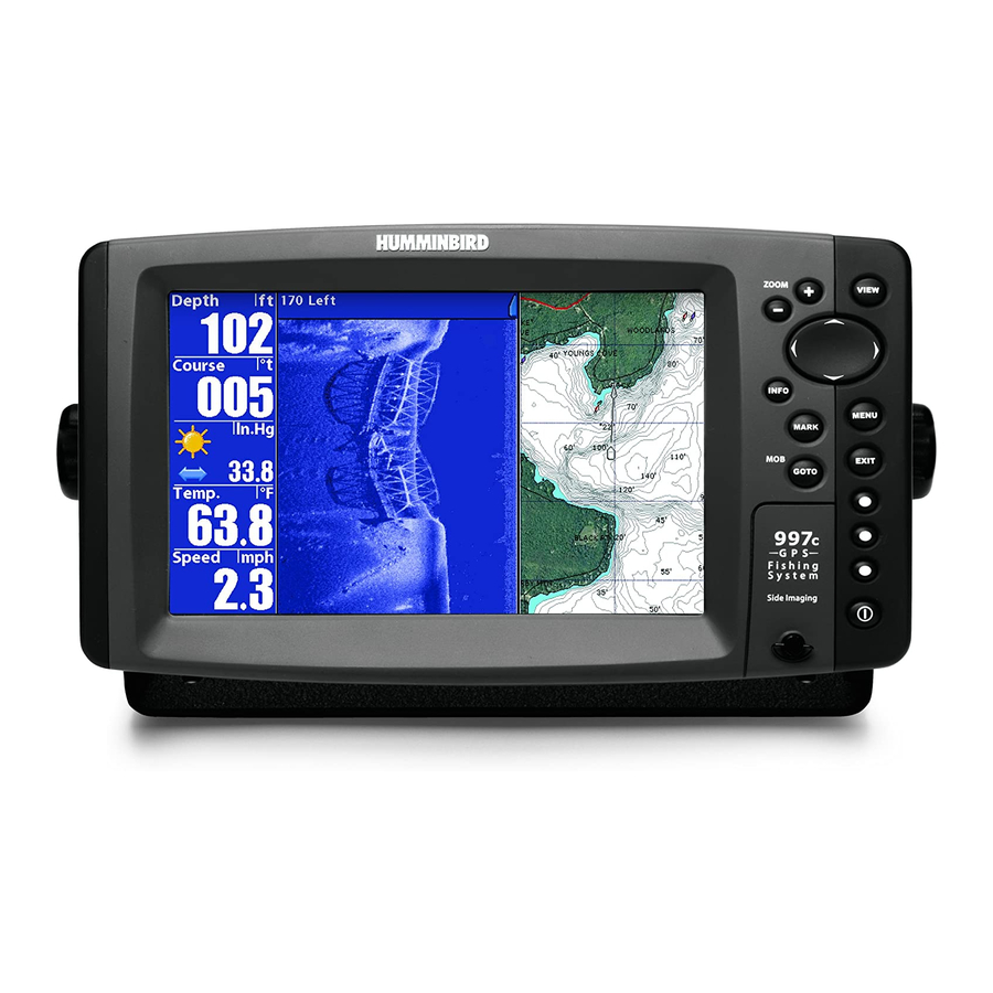
900 Series™ Introduction Your 900 Series™ Ultra Wide Screen Fishing System comes in the following configuration: • Humminbird® 997c Combo: Ultra Wide Screen Fishing System with Chartplotter (Maps) and Side Imaging and Dual Frequency Transducer, GPS Receiver included. How Sonar Works Sonar technology is based on sound waves. -
Page 9: High Definition Side Imaging Sonar
High Definition Side Imaging Sonar Your 900 Series™ 997c SI Combo uses Side Imaging sonar to provide a wide yet precise survey of a large area of water, including detailed bottom topography and fish-attracting structure orientation. -
Page 10: Dualbeam Plus™ Sonar
DualBeam PLUS™ Sonar Your 900 Series™ Fishing System uses a 200/83 kHz DualBeam PLUS™ sonar system with a wide (60°) area of coverage. DualBeam PLUS™ sonar has a narrowly focused 20° center beam, surrounded by a second beam of 60°, expanding your coverage to an area equal to your depth. -
Page 11: Universal Sonar 2
With once per second updates, the GPS receiver then calculates its velocity and bearing. The GPS Receiver included with your 900 Series™ Fishing System allows you to combine easy-to-use FishingGPS® chartplotter and navigation capabilities with advanced fishfinding. -
Page 12: Multi-Media Card (Mmc)/Sd Slot
North America (Domestic models) or a more detailed map of Europe and Southeast Asia, including Australia and New Zealand (International models). Your 900 Series™ uses the GPS Receiver to determine the position of the boat automatically, and uses the zoom level settings on a particular view to select the best chart to display. -
Page 13: Installation Overview
Operations Manual for additional details. NOTE: Accessories to enable WeatherSense® and the SmartCast® Wireless Sonar Link require separate purchases. You can visit our website at www.humminbird.com or contact our Customer Resource Center at 1-800-633-1468 for additional details. Installation Overview Please read all instructions that are relevant for your configuration before beginning the installation process. -
Page 14: Control Head Installation
Customer Resource Center at 1-800-633-1468. Control Head Installation You have two choices for mounting your 900 Series™ control head, Gimbal mounting, where you use a surface on the boat, such as the dash, to mount the control head so that it can be tilted up or down, or In-dash mounting, which requires a separate purchase. - Page 15 2. Place a 1" (25 mm) diameter black washer on the gimbal knob and then thread the knob and washer into the housing. Tighten the gimbal knob to secure the 900 Series™ control head to the mount. Repeat step 2 for the other side.
- Page 16 Mounting Screws Washer 5. Set the gimbal bracket aside and drill the four mounting screw holes using a 5/32" (4.0 mm) drill bit. 6a. If the cables must pass through a hole directly beneath the mounting bracket, mark and drill an additional 1" (25 mm) hole centered between the four mounting holes.
- Page 17 Cables Routed Directly Beneath Mounting Bracket Gimbal Bracket Hole Cover Gimbal Bracket Grommet Hole Cover 9. Insert cable connectors into the proper recesses on the cable collector insert. The cable connectors are keyed to prevent reverse installation, so be careful not to force the connectors into the wrong slots.
- Page 18 Screws cables together and create a cleaner assembly. Cable Collector Cover Tab on Insert The Humminbird® 900 Series™ control head is now ready for operation. Slot on Cover 10. While holding cables in place in Plug Cable Connector Assembly to...
-
Page 19: Connecting The Control Head Power Cable To The Boat
1b. If you need to wire the control head directly to a battery, obtain and install an inline fuse holder and a 3 amp fuse (not included) for the protection of the unit. Humminbird® is not responsible for overvoltage or over-current failures. -
Page 20: Transducer Installation
NEW and UNASSEMBLED, with mounting hardware included, for a transducer appropriate for your application - often at very little or no charge depending on the transducer. Call the Humminbird® Customer Resource Center at 1-800-633-1468 for details and pricing, or visit www.humminbird.com. -
Page 21: Transom Transducer Installation
Transom Transducer Installation If you will be installing a transom mounted transducer, use the procedures in this section. There are two pieces to the transducer mount assembly: the pivot, and the bracket. Your transducer comes with a two-piece metal and plastic bracket assembly. - Page 22 • The hydrodynamic shape of your transducer allows it to point straight down without deadrise adjustment. • On boats with stepped hulls, it may be possible to mount the trans- ducer on the step. Do not mount the transducer on the transom behind a step to avoid popping the transducer out of the water at higher speeds;...
- Page 23 Attaching the Bracket 5. Align the metal mounting bracket with the mounting holes. The center slot should be above the two outer slots. (This bracket and all other hardware supplied is top quality stainless steel for maximum strength and corrosion protection.) Insert the three 1" (25 mm) flat head wood screws into the drilled holes, but do not completely tighten.
- Page 24 To mount the transducer pivot assembly to the bracket: 1. Slide the assembled transducer into the metal bracket from the bottom, aligning the large hole at the top of the bracket with the hole in the pivot. 2. Insert the headed pin through the pivot holes in the bracket and pivot.
- Page 25 50' (15 m). For assistance, contact the Customer Resource Center at www.humminbird.com or call 1-800-633-1468 for more information. NOTE: Since the transducer may need to pivot up to 90° in the bracket if it strikes an object, make sure there is sufficient cable slack to accommodate this motion.
-
Page 26: Trolling Motor Transducer Installation
• Two control heads with one transducer • Two transducers with one control head. NOTE: Call the Humminbird® Customer Resource Center (1-800-633-1468) for details and pricing, or visit www.humminbird.com for more information. If you don’t have a trolling motor transducer, there are several options: •... -
Page 27: Test And Finish The Transducer Installation
Test and Finish the Transducer Installation When you have installed both the control head, the transducer, and accessories and have routed all the cables, you must perform a final test before locking the transducer in place. Testing should be performed with the boat in the water, although you can initially confirm basic operation with the boat out of the water. -
Page 28: Gps Receiver Installation
GPS receiver, follow the instructions included with that hardware to mount the stem (antenna pole). NOTE: AS-EC10 10' extension cables are available from Humminbird® if your planned routing exceeds 20', (6 m). Maximum cable length, including extensions, should not exceed 50' (16 m). -
Page 29: Access Under Mounting Location
3. Use electrical tape to secure the NMEA pigtail to the cable as shown. NOTE: Leave the NMEA pigtail secured to the cable unless needed. This will make removing the receiver easier. 4. Route the GPS receiver cable through the stem and continue with the planned route you chose in step 1. -
Page 30: No Access Under Mounting Location
1. Determine the best location, then test route the cable from the mounting location to the control head. NOTE: AS-EC10 10' extension cables are available from Humminbird® if your planned routing exceeds 20', (6 m). Maximum cable length, including extensions, should not exceed 50' (16 m). -
Page 31: Testing The System Installation
3. From the System Status screen, view accessory connections by NOTE: The speed will be detected only if the paddlewheel has moved since the 900 Series™ has been powered up. 4. From the System Status screen, see a GPS Diagnostic View by the Start-Up Options menu. -
Page 32: Getting Started - Using Your 900 Series
MARK Key Powering Up the Control Head Turn on your 900 Series™ control head by pressing the POWER key. The Title screen is displayed until the 900 Series™ begins operation. Your 900 Series™ will begin Normal or Simulator operation, depending on the presence or absence of a transducer. -
Page 33: What's On The Sonar Display
What’s On the Sonar Display The 900 Series™ can display a variety of useful information about the area under and adjacent to your boat, including the following items: Depth - water depth; can be set to alarm when the water becomes too shallow. -
Page 34: Understanding Sonar History
Understanding Sonar History It is important to understand the significance of the 900 Series™ display. The display does NOT show a literal 3-dimensional representation of what is under the water. Each vertical band of data received by the control head and plotted on the display represents something that was detected by a sonar return at a particular time. -
Page 35: Sonar Bottom Presentation
Sonar Bottom Presentation As the boat moves, the unit charts the changes in depth on the display to create a profile of the Bottom Contour. The type of bottom can be determined from the return charted on the display. A Hard Bottom such as compacted sediment or flat rock appears as a thinner line across the display. -
Page 36: Understanding Side Imaging
Understanding Side Imaging It is important to understand how Side Imaging technology produces the display available on the 900 Series™. The images you see on the display are produced using sonar technology. The special transducer produces three distinct beams – one beam facing down and two beams pointing out to the side. -
Page 37: What's On The Side Imaging Display
Barometric Pressure - Requires optional-purchase WeatherSense® Temperature - water surface temperature Speed - if a Speed accessory or GPS Receiver is attached, the 900 Series™ can display the speed of the boat, and can keep a triplog of nautical or statute miles traveled. -
Page 38: Side Imaging Technology: How It Works
Side Imaging Technology: How it works Side Imaging sonar uses two very precise sonar beams that are directed to either side of the boat and “illuminate” the bottom contour, structure, and fish, and display results in a “picture-like” image. • Side beams are extremely narrow from front to back, and provide “thin slices”... - Page 39 Boat navigation: It is important to understand that when the boat turns, successive beam strips to one side will begin to overlap and the strips on the other side will fan out, providing some distortion to the image. Because of this, the best imaging performance is produced by straight line navigation and minimal side-to-side boat motion (i.e.
- Page 40 Submerged Bridge: A Closer Perspective Submerged Bridge Submerged Bridge, Alternative Perspective Submerged Bridge Bait fish Swimming pool Submerged Standing and Fallen Timber, Plus Bait Fish Standing and fallen timber Submerged Swimming Pool...
-
Page 41: Key Functions
Dumped logs Key Functions Your 900 Series™ user interface consists of a set of easy-to-use keys that work with various on-screen views and menus to give you flexibility and control over your fishing experience. Your control head has the following keys: •... -
Page 42: View Key
Press and hold the POWER/LIGHT key for 3 seconds to turn the unit off. A message will appear telling you how many seconds there are until shutdown occurs. Your 900 Series™ should always be turned off using the POWER/LIGHT key. This will ensure that shutdown occurs properly and any menu settings will be saved. -
Page 43: 4-Way Cursor Control Key
4-WAY Cursor Control Key The 4-WAY Cursor Control Key has multiple functions, depending on the situation: Freeze Frame - Pressing any arrow on the 4-WAY Cursor Control key will freeze the display in the Sonar View and a cursor and cursor dialog box will be displayed. -
Page 44: Info Key
INFO Key Press the INFO key while in any navigation view to display information about objects that are nearest to an active cursor. If the cursor is not active, the following menu will be displayed. Use the 4-WAY Cursor Control key to select Nearest Port, Nearest Tide Station or Nearest Current Station, then use the RIGHT Cursor key to display the requested information. -
Page 45: Zoom (+/-) Keys
Press the - or + ZOOM keys while in the Side Imaging View to change the scale of the view. The cursor must be active for zoom to work in the Side Imaging View. Views The views available on your 900 Series™ are: Side Imaging View Side Beam... -
Page 46: Views And Readouts
Views and Readouts All views have an Information Bar on the left side of the screen, consisting of readouts that are stacked vertically, and that change from view to view. You can customize the information displayed in individual readouts on many views, including suppressing a particular readout so that nothing is displayed;... -
Page 47: Sonar View
Sonar View Sonar View presents a historical log of sonar returns. The most recent sonar returns are charted on the right side of the window; as new information is received, the older information is moved across the display to the left. A scale with Upper and Lower Depth Range readouts appears along the right edge of the Sonar View. -
Page 48: Sonar Zoom View
Sonar Zoom View Sonar Zoom View increases the displayed resolution to separate sonar returns that are very close together, such as those caused by fish suspended close to the bottom or within structure. In Zoom View, the display is split to show a narrow slice of the full range view on the right and the zoomed view on the left. -
Page 49: Split Sonar View
Split Sonar View Split Sonar View displays sonar returns from the 83 kHz wide beam on the left side of the screen and displays sonar returns from the 200 kHz narrow beam on the right side of the screen. You can use the Split Sonar View to make side by side comparisons between the sonar returns from the 83 kHz wide beam and the 200 kHz narrow beam. -
Page 50: Side/Sonar Combo View
Side/Sonar Combo View Side/Sonar Combo View shows regular sonar information and side imaging sonar information in a combination split screen. You can perform any of the functions for either of these views, but only when the view you want to control is selected as the active side (see Sonar X-Press™... -
Page 51: Snapshot And Recording View
Snapshot and Recording View Snapshot and Recording View displays and allows you to view both screen snapshot thumbnails and recording icons captured to an optional-purchase MMC/SD card installed in your unit. In addition, when you are in the Snapshot and Recording View, Start Recording, Stop Recording, Delete Image, Delete All Images, Delete Recording, Delete All Recordings, Pings Per Second, Playback Speed and Stop Playback are added to the X-Press™... - Page 52 Screen Snapshot: When Screen Snapshot is enabled (from the Accessories menu tab), pressing the MARK key creates a saved screen capture (when you have an optional-purchase MMC/SD card installed). Once you have created a screen capture, a screen capture thumbnail is added to the Snapshot and Recording View, and is available to view at a later date.
- Page 53 4. Stopping a recording using the Snapshot and Recording X-Press™ menu. 5. Playing back a recording, using the Snapshot and Recording View and the 4-Way Cursor keys, and changing the playback speed using the Snapshot and Recording X-Press™ menu. 6. Deleting a recording using the Snapshot and Recording X-Press™ menu.
- Page 54 Playing back a recording: Highlight a recording icon (using the Up or Down 4-Way Cursor keys), then use the Right 4-Way Cursor key to start playback. During playback, all active navigation is cancelled, all other thumbnails and icons will disappear, and a "Playback" message box similar to the Simulation message will be displayed periodically.
-
Page 55: Side Beam View (With Optional-Purchase Quadrabeam Plus™ Transducer Only)
Side Beam View (only with optional-purchase QuadraBeam PLUS™ transducer) Side Beam View is only available if you have connected a QuadraBeam™ transducer accessory and when Transducer Select is set to QuadraBeam (see Sonar Menu Tab: Transducer Select). This view shows sonar information from both the left and right 455 kHz beams and the 200 kHz down-looking beam in one view. - Page 56 Classic layout: The top portion of the display presents a historical log of sonar returns from the 200 kHz down-looking sonar beam. New information in the down beam panel scrolls from right to left. The bottom portion of the display presents a historical log of sonar returns from the 455 kHz right- and left-looking sonar beams.
-
Page 57: Bird's Eye View
Bird’s Eye View Bird's Eye View shows a 3D perspective view of the track and the chart land contour from a point above and behind the boat (the eye point). As the boat turns, the eye point moves to follow the boat. Big Digits on this view provide digital data in a large, easy-to-see format. -
Page 58: Chart/Bird's Eye Combo View
Chart/Bird’s Eye Combo View Chart/Bird’s Eye Combo View shows both the Chart and Bird’s Eye views in a combination split screen. You can perform any of the functions for either of these views, but only when the view you want to control is selected as the active side (see Sonar X-Press™... -
Page 59: Chart/Chart Combo View
Chart/Chart Combo View Chart/Chart Combo View shows two versions of the Chart view in a combination split screen, so that you can see the position of the boat on one side while you zoom in or perform other functions on the other. You can perform any of the functions for the Chart view, but only on the side of the view you have selected as the active side (see Sonar X-Press™... -
Page 60: Chart View
Chart View Chart View shows cartography from the built-in UniMap™ or an optional MMC/SD map for the area surrounding your current position. The current track (also known as the position history or breadcrumb trail) showing where the boat has been, along with saved tracks, waypoints, and the current route (when navigating), are overlaid on the chart. -
Page 61: Chart/Sonar Combo View
Chart/Sonar Combo View Chart/Sonar Combo View shows both the Chart and Sonar views in a combination split screen. You can perform any of the functions for either of these views, but only when the view you want to control is selected as the active side (see Sonar X-Press™... -
Page 62: Chart/Side Combo View
Chart/Side Combo View Chart/Side Combo View shows regular chart information and side imaging sonar information in a combination split screen. You can perform any of the functions for either of these views, but only when the view you want to control is selected as the active side (see Navigation X-Press™... -
Page 63: Viewing Cartography
Chart Orientation All the chart views allow you to choose the orientation of the chart. When North-Up orientation is selected, True North is shown at the top of the display. In other words, objects located to the north of the boat are drawn above the boat. -
Page 64: Navigation
Navigation Use the 900 Series™ to establish waypoints at areas of interest and to navigate to those waypoints via a saveable route (representing the shortest intended distance between waypoints). You can also view and save tracks,... -
Page 65: Waypoints, Routes And Tracks
Your 900 Series™ can store up to 50 routes that can each contain up to 50 waypoints. -
Page 66: Save, Edit, Or Delete A Waypoint
Save, Edit, or Delete a Waypoint Save your current position as a waypoint: On any view, press the MARK key to save the current position of the boat as a waypoint. Save the cursor position as a waypoint: On the Chart or Combo view, use the Cursor key to designate the position you want to save as a waypoint. -
Page 67: Navigate To A Waypoint Or Position
Navigate to a Waypoint or Position Navigate to the cursor position: From any Chart or Combo view, use the Cursor key to select a position or waypoint to which you want to navigate. Press the GOTO key. Navigation will begin immediately. Navigate to a specified waypoint: Press the GOTO key, then choose the waypoint to which you would like to navigate from the waypoint list and press the RIGHT Cursor key to select it. -
Page 68: Save, Edit Or Delete A Route
Add or Remove a Trolling Grid: From the Waypoints submenu (accessed from the Navigation main menu), select Grid and press the RIGHT Cursor key to display a list of waypoints. Select the waypoint to which you want to add the grid. The trolling grid will appear on all of the navigation views, and can be used as a guide when trolling around a waypoint. -
Page 69: Save Or Clear A Current Track
Route Info: From the Routes submenu, select Info and press the RIGHT Cursor key. A list of saved routes will appear. Select the route for which you want information, and press the RIGHT Cursor key. The list of waypoints in the route will be shown, with the distance and bearing from each waypoint to the next, as well as the distance and bearing from the current position to the first waypoint in the route. -
Page 70: Man Overboard (Mob) Navigation
Man Overboard (MOB) Navigation As soon as you know that you have a man overboard, you should activate MOB navigation to maximize chances for a successful rescue. MOB navigation allows you create an MOB waypoint to locate the point at which your man went overboard, and the relation of the boat to that point. -
Page 71: The Menu System
Normal or Advanced User Mode, and what model you own. User Mode (Normal or Advanced): An Advanced Mode is provided for users who desire the highest level of control over the 900 Series™ and Normal Mode for users who desire greater simplicity and fewer menu choices. -
Page 72: Start-Up Options Menu
Sonar Tab, Normal Mode Total Screen Update: when you change any menu settings that affect the Sonar View, the view will update immediately (i.e. you don’t have to exit the menu to apply the change to the screen). Start-Up Options Menu Press the MENU key when the Title screen is displayed to access the Start- Up Options menu. -
Page 73: Normal Operation
Exit Normal operation by powering your 900 Series™ off. Simulator Use the Simulator to learn how to use your 900 Series™ before taking your boat on the water. The Simulator is a very powerful tool that simulates on-the- water operation, providing a randomly-updated display. We recommend going through this manual while using the Simulator, since all of the menus function and affect the display the way they actually do when in Normal operation. -
Page 74: Self Test
Self Test Screen Accessory Test Accessory Test lists the accessories connected to the system. Accessory Test Screen NOTE: The speed accessory will be detected only if the paddlewheel has moved since your 900 Series™ was powered up. -
Page 75: Gps Diagnostic View
GPS Diagnostic View GPS Diagnostic View, which is only available when a GPS Receiver is attached to you 900 Series, shows a sky chart and numerical data from the GPS receiver. The sky chart shows the location of each visible GPS satellite with its satellite number and a signal strength bar. -
Page 76: Sonar X-Press™ Menu
Sonar X-Press™ Menu The Sonar X-Press™ Menu provides access to the settings most frequently used. Press the MENU key once while in any of the Sonar Views to access the Sonar X-Press™ Menu. NOTE: Menu choices will vary depending on system settings such as whether the unit is set for Advanced User mode. -
Page 77: Split Position
Split Position Split Position allows you to adjust what percentage of the screen is taken up by the left side of any Combo View; each view may be adjusted independently; you must be in a specific view to adjust the screen size for that view. The number setting indicates the percentage taken up by the left side of the Combo View;... -
Page 78: Upper Range
Upper Range (Advanced: Sonar, Split Sonar and Active Sonar Side Views only) Upper Range sets the shallowest depth range that will be displayed on the Sonar, Split Sonar and Active Sonar Side Views. The Upper Range menu choice is available when User Mode is set to Advanced (see Setup Menu Tab: User Mode) and can only be accessed from the Sonar, Split Sonar and Active Sonar Side Views. -
Page 79: Chart Speed
Chart Speed Chart Speed determines the speed at which the sonar information moves across the display, and consequently the amount of detail shown. A faster speed shows more information in the Sonar Views and is preferred by most anglers; however, the sonar information moves across the display quickly. -
Page 80: Bottom Range (Sonar Zoom View Only, When Bottom Lock Is On)
Bottom Lock (Sonar Zoom View only) Bottom Lock changes the mode of the Zoomed view in the Sonar Zoom View. To turn on Bottom Lock: 1. In the Sonar Zoom View, highlight Bottom Lock on the Sonar X-Press™ Menu. 2. Use the LEFT or RIGHT 4-WAY Cursor Control keys to change the Bottom Lock setting to on. -
Page 81: Side Imaging X-Press™ Menu
Side Imaging X-Press™ Menu (Side Imaging Views only) The Side Imaging X-Press™ Menu provides access to the settings most frequently-used. Press the MENU key once while in any of the Sonar Views to access the Side Imaging X-Press™ Menu. Side Imaging X-Press™ Menu Active Side Active Side allows you to select which side of a Combo View will be active;... -
Page 82: Si Side
SI Side SI Side sets which transducer beam from the SI beams will be shown on the display. To Adjust SI Side: 1. Highlight SI Side on the Side Imaging X-Press™ Menu. 2. Use the RIGHT 4-WAY Cursor Control key to select the transducer beam (Left, Both, Right, Default = Both) SI Sensitivity SI Sensitivity controls how much detail is... -
Page 83: Si Colors
SI Colors SI Colors allows you to select which color palette you would like to use for the display. To change the SI Colors: 1. Highlight SI Colors on the Side Imaging X-Press™menu. 2. Use the LEFT or RIGHT 4-WAY Cursor Control keys to change the color palette. -
Page 84: Active Side
Active Side Active Side allows you to select which side of a Combo View will be active; key presses will only affect the active side of the screen. When a menu is displayed, the non-active side of the screen will be grayed out;... -
Page 85: Cursor To Waypoint (Chart Or Combo View Only)
Target allows you to apply a target to a waypoint selected from the list of waypoints. Grid allows you to apply a trolling grid to a waypoint selected from the list of waypoints. Cursor to Waypoint (Chart or Combo view only) Cursor to Waypoint allows you to quickly move the cursor to any saved waypoint, so that you can locate it or edit it. -
Page 86: Save Current Route (Only When Navigating)
Save Current Route (Only when navigating) Save Current Route allows you to save the current route being displayed. This menu choice will only appear when you are currently navigating a route. To Save Current Route: 1. Highlight Save Current Route on the Navigation X-Press™ Menu. 2. -
Page 87: Waypoint Name (Most Recently-Created Waypoint)
Remove Target (Only if a Target is active) Remove Target removes the waypoint target from the display. This menu choice will only appear when a target has already been applied to a waypoint. To Remove a Target: 1. Highlight Remove Target on the Navigation X-Press™ Menu. 2. -
Page 88: Snapshot And Recording X-Press™ Menu (Snapshot And Recording View Only)
Delete allows you to delete a waypoint from the list of saved waypoints. Go To allows you to select a waypoint and start navigation toward that waypoint, or add that waypoint to the end of the current route. Target allows you to apply a target to a waypoint selected from the list of waypoints. -
Page 89: Start Recording
Start Recording (optional-purchase MMC/SD Card, Snapshot and Recording View only) Start Recording allows you to start sonar recording from the Snapshot and Recording View. This menu option is only available when you have an optional-purchase MMC/SD card installed and you are in Snapshot and Recording View. -
Page 90: Delete All Images
Delete All Images (optional-purchase MMC/SD Card, Snapshot and Recording View only) Delete All Images allows you to delete all the images at once from the Snapshot and Recording View. This menu option is only available when you have an optional-purchase MMC/SD card installed and you are in Snapshot and Recording View. -
Page 91: Delete All Recordings
Delete All Recordings (optional-purchase MMC/SD Card, Snapshot and Recording View only) Delete All Recordings allows you to delete all the recordings at once from the Snapshot and Recording View. This menu option is only available when you have an optional-purchase MMC/SD card installed and you are in Snapshot and Recording view. -
Page 92: Stop Playback (Optional-Purchase Mmc/Sd Card Only)
Stop Playback (optional-purchase MMC/SD Card only) Stop Playback allows you to stop playback of a sonar recording from any view. This menu option is only available when you have an optional- purchase MMC/SD card installed and you are playing back a recording. To stop playback of a recording: 1. -
Page 93: Beam Select
Beam Select Beam Select sets which sonar returns from the transducer will be displayed on the screen. When set to 200/83 kHz, the returns from both beams are blended. The Split Sonar View continues to display the sonar returns from each beam in their respective windows. -
Page 94: Fish Id
83 kHz, wide beam blue fish symbols orange fish symbols When Fish ID+™ is turned off, the 900 Series™ shows only the raw sonar returns on the display. These returns will often result in "arches" forming on the display, indicating potential targets. Due to the transducer beam angle,... -
Page 95: Fish Id Sensitivity
This is helpful when seeking larger species of fish. Fish Sensitivity is used in conjunction with Fish ID+™. Fish ID+™ must be On for Fish Sensitivity to affect the ability of the 900 Series™ to identify sonar returns as fish. -
Page 96: Bottom View
Bottom View Bottom View selects the method used to represent bottom and structure on the display. Structure ID® represents weak returns in blue and strong returns in red. WhiteLine® highlights the strongest sonar returns in white resulting in a distinctive outline. This has the benefit of clearly defining the bottom on the display. -
Page 97: Depth Lines (Advanced)
NOTE: The 455 kHz Sensitivity requires the purchase of the QuadraBeam PLUS™ transducer. You can visit our website at www.humminbird.com to order this accessory online or contact our Customer Resource Center at 1-800-633-1468. NOTE: 455 kHz Sensitivity is particularly useful for adjusting the sensitivity of the 455 kHz sonar returns in the Side Beam View. -
Page 98: Surface Clutter (Advanced)
Surface Clutter (Advanced) Surface Clutter adjusts the filter that removes surface clutter noise caused by algae and aeration. The lower the setting, the less surface clutter will be displayed. The Surface Clutter menu choice is available when User Mode is set to Advanced (see Setup Menu Tab: User Mode). -
Page 99: Max Depth (Advanced)
Max Depth adjusts the maximum depth of operation. The performance of your 900 Series™ can be tuned to the maximum depth you will be fishing in by setting the Max Depth. When a maximum depth is set, your 900 Series™... -
Page 100: Transducer Select
Transducer Select Transducer Select allows you to select which transducer you want to use, High-Definition Sidescan, Compact Sidescan, Sidescan, QuadraBeam PLUS™, DualBeam PLUS™, Dual 50/200 kHz, or Universal Sonar 2. NOTE: The transducer setting must correspond to the transducer type connected to your system. -
Page 101: Navigation Menu Tab
Navigation Menu Tab Press the MENU key twice to access the Main Menu System, then press the RIGHT cursor key to select the Navigation tab. NOTE: Menu choices will vary depending on system settings. Navigation Menu Current Track Current Track allows you to view the Current Track submenu. -
Page 102: Saved Tracks
Saved Tracks Saved Tracks allows you to view the Saved Tracks submenu. To view the Saved Tracks Submenu: 1. Highlight Saved Tracks on the Navigation main menu. 2. Use the RIGHT 4-WAY Cursor Control keys to view the Saved Tracks submenu. -
Page 103: Routes
Delete allows you to delete a waypoint from the list of saved waypoints. Cursor To allows you to move the cursor quickly to a waypoint selected from the list of saved waypoints. Go To allows you to select a waypoint and start navigation toward that waypoint, or add that waypoint to the end of the current route. -
Page 104: North Reference
North Reference North Reference allows you to have bearings displayed with one of two orientations: True North or Magnetic North. To change the North Reference setting: 1. Highlight North Reference on the Navigation main menu. 2. Use the LEFT or RIGHT 4-WAY Cursor Control keys to change the North Reference setting. -
Page 105: Track Min Distance (Advanced)
(Advanced) Map Datum allows you to change the map coordinate system used by the 900 Series™ to match those of a paper map. To change the Map Datum setting: 1. Make sure you are in Advanced User Mode, then highlight Map Datum on the Navigation main menu. -
Page 106: Course Projection Line
Course Projection Line Course Projection Line allows you to display or hide an arrow extending from the bow of the boat that projects your current course, and shows where the boat will go if you continue on your present course. To change the Course Project Line setting: 1. -
Page 107: Chart Menu Tab
Chart Menu Tab Press the MENU key twice to access the Main Menu System and then press the RIGHT Cursor key to select the Chart tab. NOTE: Menu choices will vary depending on system settings such as whether the unit is set for Advanced User mode. -
Page 108: Map Borders
Map Borders Map Borders allows you to display or hide map borders. A Map Border indicates an area which contains a different map. Map Borders, shown with Optional-Purchase Navionics® Cartography Map Borders To change the Map Borders setting: 1. Highlight Map Borders on the Navigation main menu. 2. -
Page 109: Navaids On Bird's Eye View
Navaids on Bird's Eye View Navaids on Bird's Eye View allows you to display or hide additional navigational aids, such as lights and buoys, in Bird's Eye View. NOTE: You will see more navigational aids with and optional-purchase MMC/SD card. To change the Navaids on Bird's Eye View setting: 1. -
Page 110: Set Map Offset (Advanced)
Set Map Offset (Advanced) Set Map Offset allows you to change the map offset used by the 900 Series™. NOTE: The Map Offset will be applied to all maps and not just the map that requires the correction. The Map Offset should be cleared if a different map is to be used. -
Page 111: Alarms Menu Tab
[International models only], Default = OFF) Fish ID Alarm Fish 900 Series™ detects fish that correspond to the alarm setting. Fish ID Alarm will only sound if Fish ID+™ is on. For example, if you've set the Fish ID Alarm to sound for Large fish only, the Fish ID alarm will sound when a large-sized fish is detected. -
Page 112: Low Battery Alarm
The battery alarm will only sound for the battery that is connected to the 900 Series™. The Low Battery Alarm should be set to warn you when the battery voltage drops below the safety margin that you have determined. -
Page 113: Temp Alarm
Temp Alarm Temp Alarm sounds when the water temperature detected by the 900 Series™ reaches the Temp Alarm setting, which is either set in degrees Fahrenheit or Celsius [International models only]. For example, if the Temp Alarm is set to 58° Fahrenheit, and the water temperature falls from 60°... -
Page 114: Arrival Alarm
Arrival Alarm Arrival Alarm sounds when the boat has either exceeded the distance to the destination waypoint, or has entered the Arrival Alarm Circle, based on the menu setting when navigating. Arrival Alarm allows you to set how close the boat must be to the destination waypoint before the Arrival Alarm will sound. -
Page 115: Alarm Tone
Alarm Tone Alarm Tone selects the pitch of the alarm sound. A brief tone will be produced as you adjust the Alarm Tone so that you can select the tone that you can hear best. To change the Alarm Tone setting: 1. -
Page 116: Units - Depth
Units - Depth Units - Depth selects the units of measure for all depth-related readouts. To change the Units - Depth setting: 1. Highlight Units - Depth on the Setup menu. 2. Use the LEFT or RIGHT 4-WAY Cursor Control keys to change the Units - Depth setting. -
Page 117: User Mode
User Mode User Mode sets the menu system to either Normal or Advanced. When set to Normal, only the basic menu options are shown. When set to Advanced (default setting), additional menu choices are available. To change the User Mode setting: 1. -
Page 118: Select Readouts (Advanced)
Select Readouts allows you to customize the information displayed in individual digital readouts on the left side of many views, including suppressing a particular readout so that nothing is displayed; the ability to customize readouts depends on the view and whether you are navigating. This Advanced feature allows you to select what data will be displayed in each of 5 fixed-position data windows arranged at the left edge of the Sonar View screen, or... -
Page 119: Depth Offset (Advanced)
Default Sonar View Customized Sonar View To Select Readouts: 1. Make sure you are in Advanced User Mode, then highlight Select Readouts on the Setup main menu. 2. Use the RIGHT 4-WAY Cursor Control key to initiate this procedure. 3. The Select Readouts submenu will appear, showing a list of all Readouts. -
Page 120: Aux Temp Offset
Aux Temp Offset (Advanced) Aux Temp Offset will adjust the aux temperature readout (the temperature on the optional-purchase temperature probe or Temp/Speed accessory) by the amount entered. This menu choice is available only when in Advanced User Mode (see Setup Menu Tab: User Mode.) To change the Aux Temp Offset setting: 1. -
Page 121: Daylight Saving Time (Advanced)
Daylight Saving Time (Advanced) Daylight Saving Time adjusts the time display to account for local Daylight Saving Time. Selecting On adds one hour to the time display adjusted for your local time zone. Selecting Off leaves the time display as adjusted for your local time zone. -
Page 122: Digits Format (Advanced)
Digits Format (Advanced) Digits Format allows you to add a tenth decimal place to readouts such as Temperature and Depth. The format can be changed to small format, large format or no format. This menu choice is available only when in Advanced User Mode (see Setup Menu Tab: User Mode.) To change the Digits Format setting: 1. -
Page 123: Sonar
Sonar Sonar deactivates Sonar and removes the Sonar Views from the view rotation. To turn Sonar on or off: 1. Highlight Sonar on the Setup menu. 2. Use the LEFT or RIGHT 4-WAY Cursor Control keys to change the Sonar to On or Off (Off, On, Default = On). Views Menu Tab From any view, press the MENU key twice to access the tabbed Main Menu System, then... - Page 124 The following views are available: • Bird’s Eye View • Chart/Bird’s Eye Combo View • Chart/Chart Combo View • Chart View • Chart/Sonar Combo View • Chart/Side Combo View • Side Imaging View • Sonar View • Sonar Zoom View •...
-
Page 125: Accessories Menu Tab
(no accessories attached) NOTE: Accessories to enable WeatherSense® and the SmartCast® Wireless Sonar Link (WSL) require separate purchases. You can visit our website at www.humminbird.com or contact our Customer Resource Center at 1-800-633-1468 for additional details. snapshot function. When Screen Snapshot is enabled, pressing the MARK key creates a saved screen capture on the optional-purchase MMC/SD card installed in your unit’s card slot. - Page 126 To turn Screen Snapshot on or off: 1. Highlight Screen Snapshot on the Accessories main menu. 2. Use the LEFT or RIGHT 4-WAY Cursor Control keys to turn Screen Snapshot On or Off (Off, On, Default = Off). To make a screen snapshot (Screen Snapshot must be enabled): 1.
-
Page 127: Troubleshooting
900 Series™ Doesn’t Power Up If your 900 Series™ doesn’t power up, use the Installation Guide that also comes with it for specific confirmation details, making sure that: • the power cable is properly connected to the 900 Series™ control head, •... -
Page 128: Display Problems
Display Problems There are several main conditions or sources of possible interference that may cause problems with the quality of the information displayed on the control head. Look in the following table for some symptoms of display problems and possible solutions: Problem The control head loses power at high speeds. -
Page 129: Finding The Cause Of Noise
Finding the Cause of Noise Electrical noise usually affects the display with many black dots at high speeds, and high sensitivity readings. One or more of the following sources can cause noise or interference: Possible Source of Noise Other electronic devices The boat’s engine Cavitation from the boat’s propeller Isolation... -
Page 130: Year Limited Warranty
This warranty is effective for one year from the date of original retail purchase. Humminbird® products found to be defective and covered by this warranty will be replaced or repaired free of charge at Humminbird’s option and returned to the customer freight prepaid. Humminbird’s sole responsibility under this warranty is limited to the repair or replacement of a product that has been deemed defective by Humminbird®. -
Page 131: Returning Your Unit For Service
We reserve the right to deem any product unserviceable when replacement parts are no longer available or impossible to obtain. This Service Policy is valid in the United States only. This applies only to Humminbird® products returned to our factory in Eufaula, Alabama. This Service Policy is subject to change without notice. -
Page 132: Series™ Accessories
900 Series™ Accessories Accessories customize the 900 Series™ to your needs and enable you to stay on the edge of new technology. When an accessory is connected to the 900 Series™, additional menus and readouts are added automatically to the Main Menu System. - Page 133 With the new InterLink™ Network Connection, you can now share GPS position, waypoints, routes and your current track between two Humminbird® Fishing Systems in real time. Mark a waypoint at the console, and it’s instantly available on the second unit. No matter where you’re at on the boat, you’ll have access to your critical fishing and navigation...
-
Page 134: Specifications
POLICY ON ENVIRONMENTAL COMPLIANCE: It is the intention of Humminbird® to be a good corporate citizen and comply and meet all known and applicable environmental regulations in the areas and countries where our products are sold. -
Page 135: Sonar Terms
Beam (Sonar Beam): A sonar beam is the wide, cone-shaped projection of sound waves formed as sound travels underwater. See Cone Angle. Big Digits View: Big Digits View is a Humminbird® feature that displays the sonar graph and enlarged digital readouts for easy reading from a distance. This is a great tool when monitoring the digital depth is important - such as with higher boat speeds, or when viewing the unit from a distance. - Page 136 Feature Memory: Feature Memory is a Humminbird® feature that retains the user's menu settings in permanent memory. Settings are retained even when the unit is powered off indefinitely.
- Page 137 Many Humminbird® units can operate across a very broad depth range (up to 2500 feet) which causes the unit to "look" up to that full depth under some circumstances.
- Page 138 See DualBeam PLUS™. Quick Disconnect Mount: The Quick Disconnect Mounting system is an exclusive Humminbird® feature that permits the unit to be easily removed from the mounting base by pressing a release button, and re-installed by simply snapping it back into place.
- Page 139 Glossary and structure. Many Humminbird® units operate at up to 40 times per second when in single frequency operation. Due to the limitation of the speed of sound in water, the update rate begins to slow as depth increases to deeper than 50 feet. In very shallow water (less than 10 feet), however, update rates as much as 60 times per second can be achieved.
- Page 140 Transducers are available for many specific mounting applications for the boat, such as a transom mount, trolling motor mount, etc. Humminbird® offers many sophisticated transducers, often with multiple piezo electric elements designed to form specifically-shaped sonar beams, providing the angler with superior tools for finding and catching fish.
- Page 141 Humminbird® offers One-Touch® Zoom which allows the zoom feature to be easily accessed from the regular sonar view with just one key press, eliminating the need to use menus to access the feature.
- Page 142 A series of geosynchronous satellites broadcast a unique signal toward the earth once per second. A GPS receiver, such as that included with many Humminbird® products, receives the signals from these satellites and is able to determine position based on very slight differences in the time each signal is received and the receiver’s knowledge of the location of each of the satellites.
- Page 143 MMC is a very rugged format suitable for the marine environment, but it is not waterproof. The MMC is removable from Humminbird® products, and can be used in a PC that is equipped with an appropriate card reader. MMC is the same format that many digital cameras use.
- Page 144 Greenwich England. (UTC is equivalent to Greenwich Mean Time (GMT)). To display the correct Local Time in a Humminbird® GPS unit, the user must use the Local Time Zone menu and select the time zone (i.e. EST, CST).
- Page 145 Humminbird® products offer the ability to name and assign a symbol to the saved location. Depth, Date and Time of Day when the waypoint was created is also saved.
-
Page 146: Contact Humminbird
Contact Humminbird® Contact the Humminbird® Customer Resource Center in any of the following ways: By Telephone (Monday - Friday 8:00 a.m. to 4:30 p.m. Central Standard Time): 1-800-633-1468 By e-mail (typically we respond to your e-mail within three business days): custserv@johnsonoutdoors.com...
Need help?
Do you have a question about the 900 Series and is the answer not in the manual?
Questions and answers