Table of Contents
Advertisement
Advertisement
Table of Contents
Troubleshooting

Related Manuals for Xantrex XS400


Summary of Contents for Xantrex XS400
- Page 1 Owner’s Guide XS400 Sine Wave Inverter...
- Page 3 XS400 Sine Wave Inverter Owner’s Guide...
-
Page 4: Contact Information
Trademarks XS400 Sine Wave Inverter is a trademark of Xantrex International. Xantrex is a registered trademark of Xantrex International. Other trademarks, registered trademarks, and product names are the property of their respective owners and are used herein for identification purposes only. -
Page 5: About This Guide
The Owner’s Guide is organized into four chapters and two appendixes. Chapter 1, “Introduction”, outlines the main performance and safety features of the XS400. Reading this chapter will give you a clear understanding of the inverter’s capabilities. Chapter 2, “Installation”, provides detailed information for installing the XS400 and the S400 Remote Switch. -
Page 6: Conventions Used
S400 Remote Switch. Details are provided on how to read the front panel indicators to monitor the XS400. Chapter 4, “Troubleshooting”, explains how to identify and solve problems that can occur with the XS400 and S400 Remote Switch. Appendix A, “Specifications”, provides the electrical and physical specifications of the XS400. - Page 7 Shore power refers to the AC input power from a utility grid, generator, or other external AC source. Related Information You can find more information about Xantrex Technology Inc. as well as its products and services at www.xantrex.com 975-0054-01-01...
-
Page 9: General Precautions
WARNING: Shock hazard The XS400 has On/Standby mode only. It does not have an Off mode, that is, DC power is permanently connected to the unit. General Precautions 1. Before installing and using the inverter, read all appropriate sections of this guide and any cautionary markings on the inverter and the batteries. -
Page 10: Precautions When Working With Batteries
Important Safety Instructions 4. To reduce the risk of electrical shock, disconnect both AC and DC power from the inverter before working on any circuits connected to the inverter. Turning the On/Standby switch to Standby ( ) will not reduce this risk. 5. -
Page 11: Fcc Information To The User
Important Safety Instructions FCC Information to the User This Class B device complies with Part 15 of the FCC Rules and all requirements of the Canadian Interference-Causing Equipment Regulations. Operation is subject to the following two conditions: (1) this device may not cause harmful interference, and (2) this device must accept any interference received, including interference that may cause undesired operation. -
Page 13: Table Of Contents
Installing the XS400 - - - - - - - - - - - - - - - - - - - - - - - - - - - - - - - - - - - - - - - - - - - - - - -2–6... - Page 14 Turning the XS400 to On or to Standby - - - - - - - - - - - - - - - - - - - - - - - - - - - - - - - 3–3...
- Page 15 Contents Warranty and Product Information - - - - - - - - - - - - - - - - - - - - - - - - - - - - - - WA–1 Warranty - - - - - - - - - - - - - - - - - - - - - - - - - - - - - - - - - - - - - - - - - - - - - - - - - - - - -WA–1 Return Material Authorization Policy- - - - - - - - - - - - - - - - - - - - - - - - - - - - - - - - - -WA–3 Out of Warranty Service - - - - - - - - - - - - - - - - - - - - - - - - - - - - - - - - - - - - - - - - - -WA–4 Information About Your System - - - - - - - - - - - - - - - - - - - - - - - - - - - - - - - - - - - - -WA–4...
-
Page 17: Introduction
Introduction Congratulations on your purchase of the Xantrex XS400 Sine Wave Inverter! The XS400 has been designed to give you premium power, ease of use, and outstanding reliability. The XS400 is bundled with the convenient S400 Remote Switch. Please read this chapter to familiarize yourself with the main performance and protection features of the XS400. -
Page 18: How Xs400 Works
Introduction How XS400 Works XS400 is a sine wave inverter which converts 12 volts direct-current (DC) power from your battery to 120 volts alternating current (AC) power. This AC power is the same as the electricity you get from your utility. In terms of output, XS400 provides 400 watts of sine wave power for operating your appliances. -
Page 19: Comprehensive Protection
Comprehensive Protection Comprehensive Protection XS400 is designed to meet UL 458 and CSA C22.2 No. 107.1 safety standards and it is compliant with FCC Class B. XS400 comes equipped with numerous protection features to guarantee you safe and worry-free operation. -
Page 20: Xs400 Features
(Shore power refers to the AC input power from a utility grid, generator or external AC source.) Inverter ON light illuminates only when the XS400 is operating in inverter mode. Low Battery light illuminates when your battery voltage is lower than 10.7 volts. -
Page 21: Back Panel
XS400 Features Back Panel Figure 1-2 Back Panel of the XS400 Table 1-2 Back Panel Features Feature Description DC terminal, negative DC terminal, positive AC input cord for shore power Wiring box access panel (For a view with the panel removed, see “Completing the Hardwiring”... -
Page 22: S400 Remote Switch
S400 Remote Switch Front Panel Inverter ON Figure 1-3 S400 Remote Switch The On/Standby switch provides remote control when the XS400 is operating in invert mode. Back Panel Figure 1-4 Connecting Cable to the S400 Remote Switch The telephone cable connects to the remote switch jack in the back. -
Page 23: Installation
Installation Chapter 2, “Installation”, provides detailed information for installing the XS400 and the S400 Remote Switch. This chapter provides: • a system diagram • safety instructions and installation codes that must be observed during installation • a list of installation tools and materials •... -
Page 24: Introduction
Installation Introduction The system diagram shown in Figure 2-1 is the basic installation. Review this diagram carefully before installing the XS400. GFCI OUTLET TELEVISION GFCI OUTLET COMPUTER ADDITIONAL LOADS AC HARDWIRING AC OUTLETS INVERTER MAIN AC PANEL AC IN (SHORE POWER) -
Page 25: Preparing For Installation
Canadian Standards Association (CSA), and RV Industry Association (RVIA) requirements for installation in RVs. WARNING: Restrictions on Use The XS400 Sine Wave Inverter shall not be used in connection with life support systems or other medical equipment or devices. 975-0054-01-01... -
Page 26: Materials List
1-604-420-2145 Email CustomerService@xantrex.com www.xantrex.com Installation Tools and Materials You will need the following tools and materials to install the XS400 and the S400 Remote Switch: Tools To install the XS400, you need: Phillips screwdriver: #2 Slot screwdrivers: 1/8 inch and 1/4 inch... - Page 27 Preparing for Installation Materials for XS400 and S400 Remote Switch To install the XS400 and S400 Remote Switch, you require: DC cables (See Table 2-1 on page 2–9.) Appropriately sized connectors. Two DC connectors suitable for ¼ inch (6 mm) that go on the DC input cable terminals. The other cable connectors will depend on your installation.
-
Page 28: Installing The Xs400
Step 1: Designing Your Installation Before doing anything else, you need to determine how you are going to use your XS400, and then design a power system that will give you maximum performance. The more thorough your planning, the better your power needs will be met. - Page 29 Allow as much space around the ventilation openings as possible. Xantrex recommends that other objects be at least 3 inches (76 mm) away from the ventilation openings for best performance. The air vented through the openings should also have a path to circulate away from the inverter.
- Page 30 Sine Wave Inverter will not operate from a 6 volt battery and will be damaged if connected to a 24 volt battery. The batteries that you use strongly affect the performance of the XS400. It is important to connect the inverter to the correct size and type of battery.
- Page 31 Installing the XS400 DC Cables For the best load starting performance, the DC cables should be as short and large as possible. See Table 2-1 for minimum recommended cable size. Using a smaller cable may cause the inverter to shut down under heavy load.
-
Page 32: Step 2: Mounting Your Inverter
For your convenience, the inverter dimensions are provided in Figure 2-9 on page 2–25. WARNING: Fire hazard To meet regulatory requirements, the XS400 must be mounted on a flat horizontal surface with the front panel in the upright position. To mount your XS400: 1. -
Page 33: Step 3: Connecting The Chassis Ground
Installing the XS400 Step 3: Connecting the Chassis Ground The chassis ground lug is used to connect the chassis of the inverter to your system’s chassis grounding point, as required by installation codes. Use copper cable that is either bare or provided with green insulation. Do not use the chassis ground lug for your AC output grounding wire. -
Page 34: Step 4: Installing The S400 Remote Switch
WARNING: Shock hazard Ensure both the S400 Remote Switch and the XS400 are in Standby ( ) mode before installing. Installing the S400 Remote Switch is optional. The XS400 operates normally without the remote switch. - Page 35 4. Connect one end of the telephone cable to the back of the inverter as shown in Figure 2-3. Figure 2-3 Connecting Cable to the XS400 5. Connect the other end of the telephone cable to the remote switch as shown in Figure 2-4.
-
Page 36: Step 5: Getting Ready To Connect The Dc Cables
The connector should be designed for a 6 mm or 1/4 inch stud size to connect to the XS400 Sine Wave Inverter. If a crimp connector is used, it should be crimped using the tool indicated by the connector manufacturer. -
Page 37: Step 6: Routing The Dc Cables
Installing the XS400 Step 6: Routing the DC Cables WARNING: Fire and shock hazard Route the cables away from sharp edges which might damage the insulation. Avoid sharp bends in the cable. Guidelines for Routing the DC Cables • Do not attempt to use the chassis in place of the battery negative connection for grounding. -
Page 38: Step 7: Connecting The Dc Cables
Installation Step 7: Connecting the DC Cables Battery Inverter Figure 2-5 Connection Order for DC Cables CAUTION: Reverse polarity Before making the final DC connection, check cable polarity at both the battery and the inverter. Positive (+) must be connected to positive (+);... - Page 39 (–) is connected to the negative (–). 10. Connect the other connector of the NEGATIVE (–) cable onto the NEGATIVE (–) terminal on the XS400 Sine Wave Inverter. 11. Use a wrench to tighten the nut to a torque of 2.2–2.6 lbf-ft...
-
Page 40: Step 8: Connecting Your Appliances To The Gfci Outlets
Note: Ensure that the Reset button on the GFCI outlets is not tripped. Important: If you have more permanent loads to connect to the inverter, Xantrex recommends that they be hardwired. See “Step 9: Hardwiring the AC Output” on page 2–19. 2–18... -
Page 41: Step 9: Hardwiring The Ac Output
Installing the XS400 Step 9: Hardwiring the AC Output If you wish to permanently connect additional AC outlets, Xantrex recommends hardwiring the AC output connections. WARNING: Fire, shock, and energy hazards Make sure wiring is disconnected from all electrical sources before handling. - Page 42 Installation 3. Locate the wiring box access panel, and remove the three screws to access the wiring box as shown in Figure 2-7. Figure 2-7 Removing the 3 Screws on the Wiring Box Access Panel 4. Remove the wiring box access panel from the unit. 5.
- Page 43 Installing the XS400 13. Tighten the wire attachment screws to a torque of 1.3–1.8 lbf-ft (1.76–2.44 Nm) as shown in Figure 2-8. Leave some slack inside the output wiring box. 14. Secure the cable clamp on the cable jacket. 15. Attach the wiring box access panel and tighten the three screws.
-
Page 44: Step 10: Performing Checks Prior To Initial Start-Up
Before starting up your inverter, ensure these conditions are met: Chassis ground is properly installed On/Standby switch is in the Standby ( ) position on both the XS400 and S400 Remote Switch Positive (+) battery cable is connected to the positive (+) battery terminal through the DC fuse and Disconnect or DC circuit breaker Negative (–) battery cable is connected to the negative (–) battery... -
Page 45: Step 12: Testing Your Installation
The On/Standby switches on the XS400 and the S400 Remote Switch do not disconnect DC or AC input power to the XS400. There are two tests to be performed. The first test verifies that the XS400 operates in invert mode. The second test verifies that the XS400 operates in shore power mode. - Page 46 Installation 4. If the appliance operates, your installation is successful. 5. If your appliance doesn’t operate, refer to “Troubleshooting” on page 4–1. 2–24 975-0054-01-01...
- Page 47 Installing the XS400 Figure 2-9 Inverter Dimensions This drawing is not to scale. A full scale mounting template is available at www.xantrex.com 975-0054-01-01 2–25...
- Page 48 2–26...
- Page 49 Installing the XS400 CUTOUT PANEL 2" X 1.2" (50.8 X 30.5) (DASHED LINE) DRILL Ø0.125 (1/8") HOLE 4 PLACES FOR #6/32 SELF TAPPING SCREW Inverter ON 0.2" TYP (5.0) 1.6" (40.8) 1.1" (28.3) 2" (50.8) Figure 2-10 S400 Remote Switch Mounting Template (Scale approximately 1:1) 975-0054-01-01 2–27...
-
Page 51: Operation
Chapter 3, “Operation” explains how to use your XS400 effectively. This chapter explains how to turn the XS400 to or Standby ( ) from the front panel or from the S400 Remote Switch, monitor the status of the XS400, and reset the inverter. CAUTION Read this chapter before operating the XS400 Sine Wave Inverter. -
Page 52: Front Panel Features
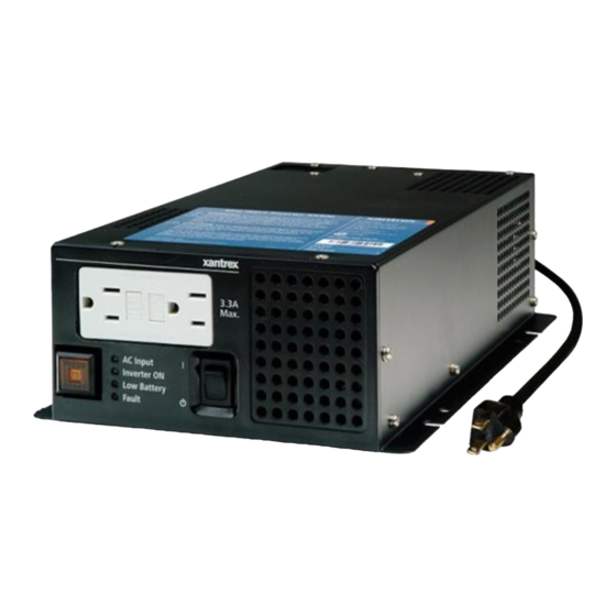
Operation Front Panel Features Before you begin to operate the XS400, review the front panel features in Figure 3-1. For a detailed description of each of the different features, see “Front Panel of the XS400” on page 1–4 in the “Introduction” chapter. -
Page 53: Operating The Xs400
Switch installed. Turning the XS400 to Standby When Not in Use If you won’t be using the XS400 for an extended period of time, turn the inverter’s On/Standby switch to the Standby ( ) position. Turning the switch to Standby ensures that the XS400 draws no current from the battery. -
Page 54: Using The S400 Remote Switch
The S400 Remote Switch provides On/Standby control only when the XS400 is operating in invert mode. only To use the S400 Remote Switch, the On/Standby switch on the XS400 must be turned to the On ( ) position. See “Operating in Invert Mode” on page 3–5. -
Page 55: Operating In Invert Mode
The Inverter ON light illuminates on the S400 Remote Switch. 3. Operate your appliances. Important: The XS400 operates normally without the S400 Remote Switch installed. If you are not using the XS400, see “Turning the XS400 to Standby When Not in Use” on page 3–3. 975-0054-01-01 3–5... -
Page 56: Recharging Your Batteries When Low Battery Light Illuminates
Recharging Your Batteries When Low Battery Light Illuminates Low battery If the Low Battery light illuminates on the XS400 while it is operating, your battery level is low (less than 10.7 volts). As long as the Inverter ON light is illuminated on the XS400, the unit will continue to supply inverter power to your appliances. -
Page 57: Operating In Shore Power Mode
(greater than 140 volts AC). In this case, the transfer from shore power to inverter power prevents damage to your appliances. S400 Remote You cannot use the S400 Remote Switch to control the XS400 when it is Switch operating in shore power mode. -
Page 58: Monitoring The Indicator Lights
XS400. See Table 3-2. For an illustration of the indicator lights on the front panel, see “Front Panel of the XS400” on page 3–2. If none of the front panel lights are on, see “Troubleshooting Reference” on page 4–2. -
Page 59: Resetting After A Fault Or Shutdown
Test: Press the Test button on the GFCI outlet with either shore power and/or the XS400 turned to On ( ). The Reset button should trip. Press the Reset button to reset the GFCI and to continue with normal operation. - Page 60 3–10...
-
Page 61: Troubleshooting
Troubleshooting The XS400 is designed for high reliability and has a number of protection features for trouble free operation. If, however, you have any problems operating your inverter or S400 Remote Switch, refer to the “Troubleshooting Reference for the XS400” on page 4–3. -
Page 62: Troubleshooting Reference
This section provides you with troubleshooting tips to identify and solve most problems that can occur with the XS400 and S400 Remote Switch. Before contacting your dealer or customer service, please refer to the tables, “Troubleshooting Reference for the XS400”... - Page 63 Troubleshooting Reference Table 4-1 Troubleshooting Reference for the XS400 Problem Possible Cause Solution No output voltage. No The On/Standby switch is in Turn the On/Standby switch on the inverter indicator lights are to On ( ). Standby ( ) mode.
- Page 64 Troubleshooting Table 4-1 Troubleshooting Reference for the XS400 Problem Possible Cause Solution No output voltage. Low Battery voltage is too low. Recharge the battery to more than 12.6 Battery light is illuminated. volts DC. The inverter will restart automatically. Poor DC wiring.
- Page 65 Troubleshooting Reference Table 4-1 Troubleshooting Reference for the XS400 Problem Possible Cause Solution Fan runs all the time. The amount of power being No action. The fan will run at lower speeds consumed by the appliances and stop automatically when the internal is high.
- Page 66 4–6...
-
Page 67: A Specifications
Specifications Appendix A, “Specifications”, contains the electrical and physical specifications for the XS400 and physical specifications for the S400 Remote Switch. All specifications are subject to change without notice. -
Page 68: Electrical Specifications Of Xs400
Supplemental circuit protector 7.5 AAC The term “watts” has been used throughout the guide to refer to output power. More correctly, the actual unit of power used is “VA”. Physical Specifications of XS400 with Projections Length 13.5 inches (343 mm) Width 7.36 inches (187 mm) -
Page 69: Regulatory Approvals
Regulatory Approvals Regulatory Approvals CSA/NRTL approved to CSA C22.2 No. 107.1 and UL 458 FCC Class B Transfer Circuit Transfer circuit 6 Amps, 85 to 140 VAC Fan Cooling System A fan cools the internal heat generating components of the inverter. The fan begins to operate when the internal temperature rises The speed of the fan increases with internal temperature. - Page 70 A–4...
-
Page 71: B Battery Types And Sizes
Battery Types and Sizes The batteries that you use strongly affect the performance of the XS400. It is important to connect the inverter to the correct size and type of battery. The information in Appendix B will help you to select, connect, and maintain batteries that are most appropriate for your application. -
Page 72: Battery Types
RV batteries, marine batteries, or golf cart batteries. For most applications of the XS400, Xantrex recommends that you use one or more deep-cycle batteries that are separated from the vehicle’s starting battery by a battery isolator. -
Page 73: Battery Size
CAUTION The XS400 Sine Wave Inverter must only be connected to batteries with a nominal output voltage of 12 volts. The XS400 Sine Wave Inverter will not operate from a 6 volt battery and will be damaged if connected to a 24 volt battery. -
Page 74: Estimating Battery Requirements
To determine how much battery capacity you need: 1. Determine how many watts are consumed by each appliance that you will operate from the XS400. You can normally find the watt rating labelled on the product. If only the current draw is given, multiply it by 115 to get the power consumption in watts. -
Page 75: Battery Sizing Worksheet
Estimating Battery Requirements This example illustrates how quickly your battery needs can escalate. To reduce the required battery size, you can conserve energy by eliminating or reducing the use of some loads or by re-charging more frequently. When sizing your battery, resist the temptation to skip the last step of this calculation (multiplying by 2). -
Page 76: Using Multiple Batteries
Two Separate Battery Banks If you need more than two batteries (or are using different makes or models of batteries), Xantrex recommends that you install two separate battery banks and a battery selector switch. By installing a battery selector switch, you can select between the two battery banks, use both banks in parallel, or disconnect both banks from the load. -
Page 77: Battery Tips
Battery Tips Battery Tips WARNING: Explosion and fire hazard Review “Precautions When Working With Batteries” on page viii before you work with the batteries in your system. Explosive/Corrosive Gases Lead-acid batteries may emit hydrogen gases, oxygen, and sulfuric acid fumes when recharging. To reduce the risk of explosion: •... - Page 78 Battery Types and Sizes Battery State of Charge You can measure battery state of charge with a hydrometer or approximate state of charge with a voltmeter. Use a digital voltmeter that can display tenths or hundredths of a volt when measuring 10 to 30 volts.
-
Page 79: Warranty And Product Information
For some products, Xantrex maintains a network of regional Authorized Service Centers. Call Xantrex or check our website to see if your product can be repaired at one of these facilities. In any warranty claim, dated proof of purchase must accompany the product and the product must not have been disassembled or modified without prior written authorization by Xantrex. - Page 80 This warranty does not apply to and Xantrex will not be responsible for any defect in or damage to: the product if it has been misused, neglected, improperly installed, physically damaged or altered, either internally or externally, or damaged from improper use or use in an unsuitable environment;...
-
Page 81: Return Material Authorization Policy
XS400 Sine Wave Inverter IN CONNECTION WITH LIFE SUPPORT SYSTEMS OR OTHER MEDICAL EQUIPMENT OR DEVICES. Please note that the XS400 Sine Wave Inverter is not intended for use as an uninterruptible power supply and Xantrex makes no warranty or representation in connection with any use of the product for such purposes. -
Page 82: Out Of Warranty Service
Out of Warranty Service If the warranty period for your XS400 Sine Wave Inverter has expired, if the unit was damaged by misuse or incorrect installation, if other conditions of the warranty have not been met, or if no dated proof of purchase is available, your inverter may be serviced or replaced for a flat fee. -
Page 83: Index
Index 3–6 battery chargers B–7 battery connections abbreviations battery isolator 2–22 AC input cord, connecting 2–15 avoiding voltage drops AC Input light B–2 using 1–4 feature described 3–6 battery monitors 1–4, 3–2 illustrated B–3 battery reserve capacity 2–20 AC output cable, requirements B–6 battery selector switch acronyms... - Page 84 Index 2–15 required See also DC fuse and Disconnect. hardwiring 2–9 DC Disconnect, minimum rating 2–19 AC output connections 2–15 DC distribution panel definition DC fuse 1–3 high voltage shutdown, feature described 2–9 maximum rating B–8 hydrometer 2–9 minimum rating DC fuse and Disconnect 2–23 closing...
- Page 85 3–3 1–2 with On/Standby switch transfer switch 2–16 reverse polarity, caution troubleshooting 4–5 remote switch 4–3 XS400 3–3 turning the XS400 to On S400 Remote Switch 3–3 turning the XS400 to standby 975-0054-01-01 IX–3...
- Page 86 1–4, 3–2 illustrated viii precautions 2–7 recommended clearance 2–15 voltage drop, avoiding B–8 voltmeter warranty WA–4 out of warranty service WA–1 terms and conditions 2–16 voiding Xantrex, web site XS400 WA–3 limitations on use 3–3 operating A–1 specifications IX–4 975-0054-01-01...
- Page 88 Xantrex Technology Inc. 604 422 2777 Tel 604 420 2145 Fax 800 670 0707 Toll Free North America CustomerService@xantrex.com www.xantrex.com 975-0054-01-01 Printed in China...
Need help?
Do you have a question about the XS400 and is the answer not in the manual?
Questions and answers