Table of Contents
Advertisement
Quick Links
Advertisement
Chapters
Table of Contents

Related Manuals for IBASE Technology MI958


Summary of Contents for IBASE Technology MI958
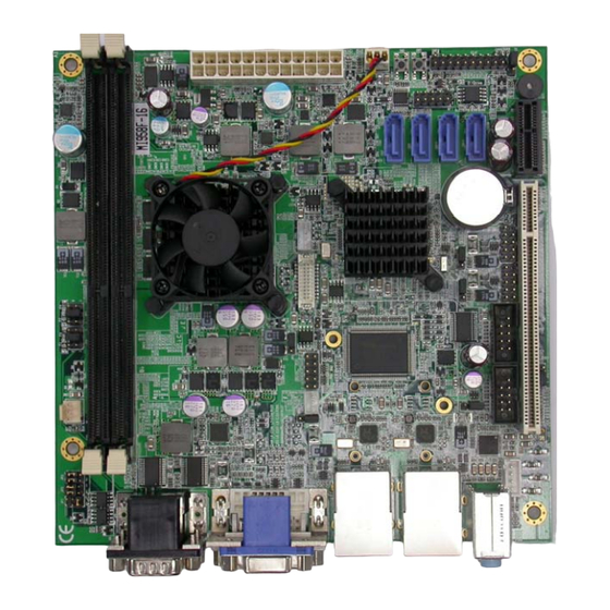
- Page 1 MI958 AMD G-series APU+A55E FCH Mini-ITX Motherboard USER’S MANUAL Version 1.0...
- Page 2 Microsoft Windows is a registered trademark of Microsoft Corporation. FINTEK is a registered trademark of FINTEK Electronics Corporation. REALTEK is a registered trademark of REALTEK Electronics Corporation. All other product names or trademarks are properties of their respective owners. MI958 User’s Manual...
-
Page 3: Table Of Contents
............1 Product Description ............1 Checklist ................2 Board Specifications ............3 Board Dimensions .............. 4 Installations ............5 Installing the Memory ............6 Setting the Jumpers ............. 7 Connectors ................ 12 BIOS Setup ............21 MI958 User’s Manual... - Page 4 THE MI958 MINI ITX MOTHERBOARD MI958 User’s Manual...
-
Page 5: Introduction
Supports Dual Core AMD Embedded G-Series Processors Supports up to DDR3-1066 MT/s Two DDR3 SDRAM DIMMs, Max.8GB memory Onboard Realtek Gigabit LAN 4x SATA-III, 8x USB 2.0, 4x COM, Watchdog timer, 1x PCI,1x PCI-E(x1) slots 1x VGA,1x DVI,1x LVDS MI958 User’s Manual... -
Page 6: Checklist
INTRODUCTION Checklist Your AMD MI958 Development Board package should include the items listed below. • The MI958 Mini-ITX motherboard • This User’s Manual • 1 CD containing chipset drivers and flash memory utility • 1 Serial ATA cable MI958 User’s Manual... -
Page 7: Board Specifications
Yes (256 segments, 0, 1, 2…255. sec/min) Watchdog Timer Power Connector ATX Power connector RoHS Others CPU cooler onboard for T56N/T48N APU ; Heatsink for T40N APU EuP feature onboard (Fintek F75160) Board Size 170mm x 170mm MI958 User’s Manual... -
Page 8: Board Dimensions
INTRODUCTION Board Dimensions MI958 User’s Manual... -
Page 9: Installations
This section provides information on how to use the jumpers and connectors on the motherboard in order to set up a workable system. The topics covered are: Installing the Memory ..............6 Setting the Jumpers ..............7 Connectors ................12 MI958 User’s Manual... -
Page 10: Installing The Memory
2. Gently push the DDR3 module in an upright position until the clips of the slot close to hold the DDR3 module in place when the DDR3 module touches the bottom of the slot. 3. To remove the DDR3 module, press the clips with both hands. DDR3 Module MI958 User’s Manual... -
Page 11: Setting The Jumpers
JP7 : USB1, USB2 (CN6) Power Setting ........10 JP11 : USB3, USB4 (CN9) Power Setting ........10 JP8 : USB5, USB6 (CN13) Power Setting ........11 JP9 : USB7, USB8 (CN14) Power Setting ........11 J11: PCI/PCIE Riser Card Selection ........... 11 MI958 User’s Manual... -
Page 12: Jumper Locations
INSTALLATIONS Jumper Locations MI958 User’s Manual... -
Page 13: Jp6: Lcd Panel Power Selection
COM1 RS-232 RS-422 RS-485 Function JP3: JP3: JP3: 3-5 & 4-6 1-3 & 2-4 1-3 & 2-4 Jumper Setting JP2: JP2: JP2: (pin closed) 3-5 & 4-6 1-3 & 2-4 1-3 & 2-4 JP1: JP1: JP1: MI958 User’s Manual... -
Page 14: Jp4 :Com1 Rs232 +5V/+12V Power Setting
JP7: USB1, USB2 (CN6) Power Setting Setting Function Pin 1-2 +5VSB Short/Closed Pin 2-3 Short/Closed JP11: USB3, USB4 (CN9) Power Setting JP11 Setting Function Pin 1-2 +5VSB Short/Closed Pin 2-3 Short/Closed JP8: USB5, USB6 (CN13) Power Setting MI958 User’s Manual... -
Page 15: Connectors
Short/Closed Pin 2-3 Short/Closed JP9: USB7, USB8 (CN14) Power Setting Setting Function Pin 1-2 +5VSB Short/Closed Pin 2-3 Short/Closed J11: PCI/PCIE Riser Card Selection Riser Card IP390 Riser Card Install IP151, IP240 Riser Card Install Motherboard Connectors MI958 User’s Manual... - Page 16 J7,J8: COM3/4 Serial Port ............17 CN4: LVDS Connector..............18 CN3: LCD Backlight Connector........... 18 CN5: Output Voltage Connector ..........18 J9: Speaker Connector ..............18 PCIE1: PCI-E(x1) Slot ..............19 PCI1: PCI Slot (supports 2 Master) ..........19 MI958 User’s Manual...
- Page 17 INSTALLATIONS Connector Locations MI958 User’s Manual...
-
Page 18: Cn1A, Cn1B: Com1(Up) And Com2(Down)Connector
FAN1 is a 3-pin header for system fan. The fan must be a 12V (500mA). Pin # Signal Name Ground +12V Rotation detection FAN2: CPU Fan Power Connector FAN2 is a 3-pin header for the CPU fan. The fan must be a 12V(500mA). Pin # Signal Name Ground +12V Rotation detection MI958 User’s Manual... -
Page 19: J3: Atx Power Supply Connector
Ground Ground Ground Ground Ground Power good 5VSB +12V +12V Ground +3.3V J4: Digital I/O Signal Name Signal Name OUT3 OUT1 OUT2 OUT0 J5: SMBUS Connector Signal Name Signal Name DATA J6: SPI Flash Connector(factory use only) MI958 User’s Manual... -
Page 20: Jp10: System Function Connector
This 2-pin connector is an “ATX Power Supply On/Off Switch” on the system that connects to the power switch on the case. When pressed, the power switch will force the system to power on. When pressed again, it will force the system to power off. MI958 User’s Manual... -
Page 21: Cn13,Cn14: Usb5/6 Usb7/8Port Pin Header
Pin # Signal Name DCD, Data carrier detect DSR, Data set ready RXD, Receive data RTS, Request to send TXD, Transmit data CTS, Clear to send DTR, Data terminal ready RI, Ring indicator GND, ground Not Used MI958 User’s Manual... -
Page 22: Cn4: Lvds Connector
Brightness Control Ground CN5: Output Voltage Connector Pin # Signal Name 3.3V Ground J9 Speaker Connector The J9 connector supports 2Watt(RMS)/4 ohm stereo audio power amplifier. Pin # Signal Name Audio L+ Audio L- Audio R- Audio R+ MI958 User’s Manual... -
Page 23: Pcie1: Pci-E(X1) Slot
INSTALLATIONS PCIE1: PCI-E(x1) Slot PCI1: PCI Slot (supports 2 Master) MI958 User’s Manual... - Page 24 INSTALLATIONS This page is intentionally left blank MI958 User’s Manual...
-
Page 25: Bios Setup
The topics covered in this chapter are as follows: BIOS Introduction ..................22 BIOS Setup ....................22 Main BIOS Setup ..................23 Advanced Settings ..................24 Chipset Settings .................... 32 Boot Settings ....................38 Security Settings ................... 39 Save & Exit Settings ..................39 MI958 User’s Manual... -
Page 26: Bios Introduction
<PgUp> and <PgDn> keys to change entries, <F1> for help and <Esc> to quit. When you enter the Setup utility, the Main Menu screen will appear on the screen. The Main Menu allows you to select from various setup functions and exit choices. MI958 User’s Manual... -
Page 27: Main Bios Setup
System Language Choose the system default language. System Date Set the Date. Use Tab to switch between Data elements. System Time Set the Time. Use Tab to switch between Time elements. MI958 User’s Manual... -
Page 28: Advanced Settings
F2: Previous Values F3: Optimized Default F4: Save ESC: Exit Launch PXE OpROM Enable or Disable Boot Option for Legacy Network Devices. Launch Storage OpROM Enable or Disable Boot Option for Legacy Mass Storage Devices with Option ROM. MI958 User’s Manual... -
Page 29: Pci Subsystem Settings
Enables or Disables VGA Palette Registers Snooping. PERR# Generation Enables or Disables PCI Device to Generate PERR#. SERR# Generation Enables or Disables PCI Device to Generate SERR#. Relaxed Ordering Enables or Disables PCI Express Device Relaxed Ordering. MI958 User’s Manual... - Page 30 System BIOS to select the value. ASPM Support Set the ASPM Level: Force L0 – Force all links to L0 State AUTO – BIOS auto configure DISABLE – Disables ASPM Extended Synch If ENABLED allows generation of Extended Synchronization patterns. MI958 User’s Manual...
-
Page 31: Acpi Settings
ACPI Sleep State Select the highest ACPI sleep state the system will enter, when the SUSPEND button is pressed. Lock legacy Resources Enabled or Disabled Lock of Legacy Resources S3 Video Repost Enabled or Disabled S3 Video Repost. MI958 User’s Manual... -
Page 32: Cpu Configuration
Provide to adjust startup P-state level. PPC adjustment Provide to adjust_PPC object. NX Mode Enabled/disabled NO-execute page protection Function. SVM Mode Enabled/disabled CPU Virtualization. C6 Mode Enabled/disabled C6. Node 0 Information View Memory Information related to Node 0. MI958 User’s Manual... -
Page 33: Ide Configuration
Enabled SATA Port2 Change Field Enabled SATA Port3 F1: General Help Enabled SATA Port4 F2: Previous Values Enabled SATA Port5 F3: Optimized Default F4: Save ESC: Exit ESC: Exit Serial-ATA Controller Enable / Disable Serial ATA Controller. MI958 User’s Manual... -
Page 34: Usb Configuration
Maximum time the device will take before it properly reports itself to the Host Controller. ‘Auto’ users default value: for a Root port it is 100ms, for a Hub port the delay is taken from Hub descriptor. MI958 User’s Manual... -
Page 35: Super Io Configuration
Temperatures/Voltages The values are read-only values as monitored by the system and show the PC health status. CPU Shutdown Temperature Aside from the Disabled options, this field allows the setting of shutdown temperature from 70C to 95C. MI958 User’s Manual... -
Page 36: Chipset Settings
F3: Optimized Default F4: Save ESC: Exit North Bridge This item shows the North Bridge Parameters. North Bridge LVDS Config Select This item shows the Specify INT15 options for LVDS South Bridge This item shows the South Bridge Parameters. MI958 User’s Manual... -
Page 37: Memory Clock
Save & Exit GFX Configuration → ← Select Screen PSPP Policy Disabled ↑↓ Select Item Enter: Select Change Field F1: General Help F2: Previous Values F3: Optimized Default F4: Save ESC: Exit PSPP Policy PCIe speed power policy. MI958 User’s Manual... -
Page 38: Memory Configuration
Select Screen DP0 Output Mode Disabled ↑↓ Select Item DP1 Output Mode Single Link DVI-D Enter: Select Change Field LVDS Panel Config Select 800x600 F1: General Help F2: Previous Values F3: Optimized Default F4: Save ESC: Exit MI958 User’s Manual... -
Page 39: Sb Sata Configuration
SATA Power on PORT3 Enabled SATA Power on PORT4 Enabled SATA Power on PORT5 Enabled OnChip SATA Type Native IDE / n RAID / n AHCI / n AHCI / n Legacy IDE / n IDE->AHCI / n HyperFlash MI958 User’s Manual... -
Page 40: Sb Usb Configuration
↑↓ Select Item NB-SB PHY PLL Power Down Enabled Enter: Select SB GPP PHY PLL Power Down Enabled Change Field SB GPP LANE REVERSAL Disabled F1: General Help F2: Previous Values F3: Optimized Default F4: Save ESC: Exit MI958 User’s Manual... - Page 41 SDIN0 Pin Config Azalia ↑↓ Select Item SDIN1 Pin Config Azalia Enter: Select SDIN2 Pin Config Azalia Change Field SDIN3 Pin Config Azalia F1: General Help Azalia Snoop Disabled F2: Previous Values F3: Optimized Default F4: Save ESC: Exit MI958 User’s Manual...
-
Page 42: Boot Settings
RT code is executed above 1MB. Option ROM Messages Set display mode for Option ROM. Options are Force BIOS and Keep Current. Interrupt 19 Canture Enable: Allows Option ROMs to trap Int 19. UEFI Option Priorities Enables/Disables UEFI boot from disks. MI958 User’s Manual... -
Page 43: Security Settings
Enter: Select Save Changes Change Field Discard Changes F1: General Help F2: Previous Values Restore Defaults F3: Optimized Default Save as User Defaults F4: Save ESC: Exit Restore User Defaults Boot Override Launch EFI Shell from filesystem device MI958 User’s Manual... - Page 44 Restore the User Defaults to all the setup options. Boot Override Pressing ENTER causes the system to enter the OS. Launch EFI Shell from filesystem device Attempts to launch EFI Shell application (Shellx64.efi) from one of the available filesystem devices. MI958 User’s Manual...
-
Page 45: Drivers Installation
Realtek High Definition Audio Driver Installation ......45 Realtek LAN Controller Drivers Installation ........47 IMPORTANT NOTE: After installing your Windows operating system, you must install first the Intel Chipset Software Installation Utility before proceeding with the drivers installation. MI958 User’s Manual... - Page 46 Installation Follow the steps below to install the AMD A55E chipset family graphics drivers. 1. Insert the CD that comes with the board. Click AMD, then AMD A55E Chipset Drivers, and then AMD A55E Series Graphics Drivers. MI958 User’s Manual...
- Page 47 DRIVERS INSTALLATIONS 2. When the welcome screen to the ATI – Catalyst™ Install Manager appears, click Next. Now, click Install to allow the installation of the software components. MI958 User’s Manual...
- Page 48 DRIVERS INSTALLATIONS 3. Select Express and click Next to proceed with the installation. On the following screen, click Finish to complete the installation process. MI958 User’s Manual...
-
Page 49: Realtek High Definition Audio Driver Installation
DRIVERS INSTALLATIONS Realtek High Definition Audio Driver Installation Follow the steps below to install the Realtek HD audio drivers. 1. Insert the CD that comes with the board. Click AMD, and then Realtek High Definition Audio Driver. MI958 User’s Manual... - Page 50 DRIVERS INSTALLATIONS 2. When the welcome screen to the Audio Driver Setup appears, click Next to start the software installation. Once the InstallShield Wizard is complete, click Finish to restart the computer. MI958 User’s Manual...
-
Page 51: Realtek Lan Controller Drivers Installation
Realtek LAN Controller Drivers Installation Follow the steps below to install the Realtek LAN Drivers. 1. Insert the CD that comes with the board. Click Intel, then LAN Card, and then Realtek Lan Controller Drivers. 2. Click Realtek RTL8111E LAN Drivers. MI958 User’s Manual... - Page 52 DRIVERS INSTALLATIONS 3.When the welcome screen to InstallShield Wizard appears, click Next to start the installation 4.When the InstallShieldWizard has finished installing the Realtek LAN drivers, click Finish. MI958 User’s Manual...
- Page 53 Graphics adapter Controller 360h - 36Fh Network Ports 3B0h - 3BFh Monochrome & Printer adapter 3C0h - 3CFh EGA adapter 3D0h - 3DFh CGA adapter 3E8h – 3EFh Serial Port #3(COM3) 3F8h - 3FFh Serial Port #1(COM1) MI958 User’s Manual...
- Page 54 Serial Port #2 IRQ4 Serial Port #1 IRQ5 Reserved IRQ6 Reserved IRQ7 Reserved IRQ8 Real Time Clock IRQ9 Reserved IRQ10 Serial Port #3 IRQ11 Serial Port #4 IRQ12 PS/2 Mouse IRQ13 80287 IRQ14 Primary IDE IRQ15 Secondary IDE MI958 User’s Manual...
-
Page 55: Sample Code
Fintek 81865, program abort.\n"); return(1); }//if (SIO == 0) if (argc != 2) printf(" Parameter incorrect!!\n"); return (1); bTime = strtol (argv[1], endptr, 10); printf("System will reset after %d seconds\n", bTime); if (bTime) EnableWDT(bTime); } else DisableWDT(); return 0; MI958 User’s Manual... - Page 56 //--------------------------------------------------------------------------- void DisableWDT(void) unsigned char bBuf; Set_F81865_LD(0x07); //switch to logic device 7 bBuf = Get_F81865_Reg(0xFA); bBuf &= ~0x01; Set_F81865_Reg(0xFA, bBuf); //disable WDTO output bBuf = Get_F81865_Reg(0xF5); bBuf &= ~0x20; bBuf |= 0x40; Set_F81865_Reg(0xF5, bBuf); //disable WDT //--------------------------------------------------------------------------- MI958 User’s Manual...
- Page 57 //--------------------------------------------------------------------------- void Set_F81865_LD( unsigned char LD) Unlock_F81865(); outportb(F81865_INDEX_PORT, F81865_REG_LD); outportb(F81865_DATA_PORT, LD); Lock_F81865(); //--------------------------------------------------------------------------- void Set_F81865_Reg( unsigned char REG, unsigned char DATA) Unlock_F81865(); outportb(F81865_INDEX_PORT, REG); outportb(F81865_DATA_PORT, DATA); Lock_F81865(); //--------------------------------------------------------------------------- unsigned char Get_F81865_Reg(unsigned char REG) unsigned char Result; Unlock_F81865(); MI958 User’s Manual...
- Page 58 (F81865_BASE) #define F81865_DATA_PORT (F81865_BASE+1) //--------------------------------------------------------------------------- #define F81865_REG_LD 0x07 //--------------------------------------------------------------------------- #define F81865_UNLOCK 0x87 #define F81865_LOCK 0xAA //--------------------------------------------------------------------------- unsigned int Init_F81865(void); void Set_F81865_LD( unsigned char); void Set_F81865_Reg( unsigned char, unsigned char); unsigned char Get_F81865_Reg( unsigned char); //--------------------------------------------------------------------------- #endif //__F81865_H MI958 User’s Manual...
Need help?
Do you have a question about the MI958 and is the answer not in the manual?
Questions and answers