Table of Contents
Advertisement
Quick Links
Advertisement
Table of Contents

Related Manuals for Extech Instruments 450


Summary of Contents for Extech Instruments 450
- Page 1 User's Guide Autoranging Multimeter plus IR Thermometer Extech 450 Patent Pending...
- Page 2 Introduction Congratulations on your purchase of the Extech 450 (part number EX450) Autoranging Multimeter plus IR Thermometer. This meter measures AC/DC Voltage, AC/DC Current, Resistance, Diode Test, and Continuity plus Non-Contact IR Temperature. Proper use and care of this meter will provide many years of reliable service.
-
Page 3: Overvoltage Category
OVERVOLTAGE CATEGORY III This meter meets the IEC 610-1-95 standard for OVERVOLTAGE CATEGORY III. Cat III meters are protected against overvoltage transients in fixed installation at the distribution level. Examples include switches in the fixed installation and some equipment for industrial use with permanent connection to the fixed installation. -
Page 4: Controls And Jacks
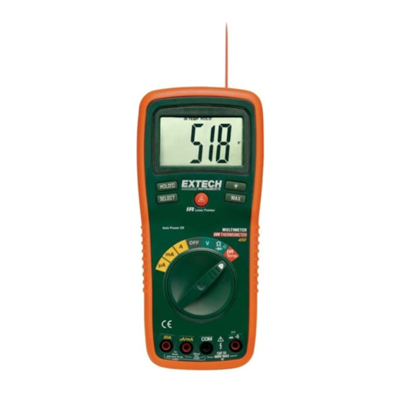
Controls and Jacks 1. IR Thermometer and laser pointer 2. 2000 count LCD display 3. HOLD button 4. SELECT button 5. Function switch 6. mA, uA and A input jacks 7. COM input jack 8. Positive input jack 9. MAX hold button (voltage and current) 10. -
Page 5: Specifications
Specifications Function Range Resolution Accuracy 200mV 0.1mV ±(0.5% reading + 2 digits) Voltage 0.001V ±(0.8% reading + 2 digits) 0.01V 200V 0.1V ±(1.0% reading + 3 digits) 1000V 50 to 400Hz 400Hz to 1kHz Voltage 0.001V ±(1.0% reading ±(2.5% reading + 4 digits) + 8 digits) 0.01V... - Page 6 Function Range Resolution Accuracy ±(0.8% reading + 4 digits) Resistance 200Ω 0.1Ω ±(0.8% reading + 2 digits) 2kΩ 0.001kΩ 20kΩ 0.01kΩ ±(1.0% reading + 2 digits) 200kΩ 0.1kΩ 2MΩ 0.001MΩ ±(3.0% reading + 5 digits) 20MΩ 0.01MΩ Temp -58 to 518°F 1°F ±2.0% reading or ±2°C, ±...
- Page 7 Battery One 9 volt (NEDA 1604) battery Fuses mA, µA ranges; 0.2A/250V fast blow A range; 20A/250V ceramic fast blow Operating Temperature 41ºF to 104ºF (5ºC to 40ºC) Storage Temperature F to 140 F (-20 C to 60 Operating Humidity Max 80% up to 87ºF (31ºC) decreasing linearly to 50% at 104ºF(40ºC) Storage Humidity...
-
Page 8: Dc Voltage Measurements
Operating Instructions WARNING: Risk of electrocution. High-voltage circuits, both AC and DC, are very dangerous and should be measured with great care. 1. ALWAYS turn the function switch to the OFF position when the meter is not in use. 2. If “OL” appears in the display during a measurement, the value exceeds the range you have selected. -
Page 9: Ac Voltage Measurements
AC VOLTAGE MEASUREMENTS WARNING: Risk of Electrocution. The probe tips may not be long enough to contact the live parts inside some 240V outlets for appliances because the contacts are recessed deep in the outlets. As a result, the reading may show 0 volts when the outlet actually has voltage on it. -
Page 10: Dc Current Measurements
DC CURRENT MEASUREMENTS CAUTION: Do not make current measurements on the 20A scale for longer than 30 seconds. Exceeding 30 seconds may cause damage to the meter and/or the test leads. 1. Insert the black test lead banana plug into the negative COM jack. -
Page 11: Ac Current Measurements
AC CURRENT MEASUREMENTS CAUTION: Do not make current measurements on the 20A scale for longer than 30 seconds. Exceeding 30 seconds may cause damage to the meter and/or the test leads. 1. Insert the black test lead banana plug into the negative COM jack. -
Page 12: Resistance Measurements
RESISTANCE MEASUREMENTS WARNING: To avoid electric shock, disconnect power to the unit under test and discharge all capacitors before taking any resistance measurements. Remove the batteries and unplug the line cords. 1. Set the function switch to the green Ω position. -
Page 13: Continuity Check
CONTINUITY CHECK WARNING: To avoid electric shock, never measure continuity on circuits or wires that have voltage on them. 1. Set the function switch to the green Ω position. 2. Insert the black lead banana plug into the negative COM jack Insert the red test lead banana plug into the positive Ω... -
Page 14: Non-Contact Temperature Measurements
NON-CONTACT TEMPERATURE MEASUREMENTS 1. Set the function switch to the red IR Temp position. 2. Press the SELECT button to select ºF or ºC 3. Point the meter at the surface to be measured. 4. If needed, press the IR Laser Pointer button to locate the exact spot being measured. -
Page 15: Display Backlight
DISPLAY BACKLIGHT Press and hold the button for >1 second to turn on or off the display backlight function. The backlight will automatically turn off after 30 seconds. Press the MAX button to activate the MAX feature in the voltage or current functions. -
Page 16: Maintenance
Maintenance WARNING: To avoid electric shock, disconnect the test leads from any source of voltage before removing the back cover or the battery or fuse covers. WARNING: To avoid electric shock, do not operate your meter until the battery and fuse covers are in place and fastened securely. -
Page 17: Battery Installation
BATTERY INSTALLATION WARNING: To avoid electric shock, disconnect the test leads from any source of voltage before removing the battery cover. 1. Turn power off and disconnect the test leads from the meter. 2. Open the rear battery cover by removing two screws (B) using a Phillips head screwdriver. -
Page 18: Replacing The Fuses
REPLACING THE FUSES WARNING: To avoid electric shock, disconnect the test leads from any source of voltage before removing the fuse cover. 1. Disconnect the test leads from the meter. 2. Remove the protective rubber holster. 3. Remove the battery cover (two “B” screws) and the battery. 4. -
Page 19: Warranty
(click on ‘Contact Extech’ and go to ‘Service Department’ to request an RA number). A Return Authorization (RA) number must be issued before any product is returned to Extech. The sender is responsible for shipping charges, freight, insurance and proper packaging to prevent damage in transit.
Need help?
Do you have a question about the 450 and is the answer not in the manual?
Questions and answers