Advertisement
Table of Contents
- 1 Overvoltage Category
- 2 Safety Instructions
- 3 Controls and Jacks
- 4 Symbols and Annunciators
- 5 DC Voltage Measurements
- 6 Ac Voltage Measurements
- 7 DC Current Measurements
- 8 Ac Current Measurements
- 9 Resistance Measurements
- 10 Continuity Check
- 11 Diode Test
- 12 Specifications
- 13 Maintenance
- 14 Replacing the Fuses
- Download this manual
Advertisement
Table of Contents

Related Manuals for Extech Instruments EX410


Summary of Contents for Extech Instruments EX410
- Page 1 User's Guide Digital Multimeter Extech 410...
- Page 2 Introduction Congratulations on your purchase of the Extech EX410 Multimeter. This meter measures AC/DC Voltage, AC/DC Current, Resistance, Diode Test, and Continuity plus Thermocouple Temperature. Proper use and care of this meter will provide many years of reliable service. Safety...
- Page 3 • Expired or damaged batteries can cause cauterization on contact with the skin. Always, therefore, use suitable hand gloves in such cases • See that the batteries are not short-circuited. Do not throw batteries into the fire. EX410-EU_ENG V5.1 10/07...
-
Page 4: Overvoltage Category
ALWAYS turn off the power and disconnect the test leads before opening the covers to replace the fuse or battery. NEVER operate the meter unless the back cover and the battery cover is in place and fastened securely. EX410-EU_ENG V5.1 10/07... -
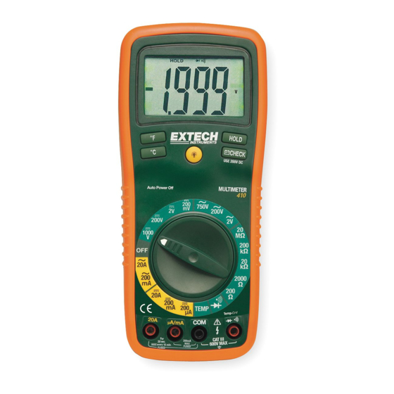
Page 5: Controls And Jacks
µ micro (10 ) (amps) milli (10 ) (volts, amps) kilo (10 ) (ohms) Ω mega (10 ) (ohms) Ohms Amps Volts Alternating current AUTO Autoranging Direct current HOLD Display hold ºF Degrees Fahrenheit ºC Degrees Centigrade EX410-EU_ENG V5.1 10/07... -
Page 6: Dc Voltage Measurements
4. Read the voltage in the display. Reset the function switch to successively lower V DC positions to obtain a higher resolution reading. If the polarity is reversed, the display will show (-) minus before the value. EX410-EU_ENG V5.1 10/07... -
Page 7: Ac Voltage Measurements
6. Touch the black test probe tip to the negative side of the circuit. Touch the red test probe tip to the positive side of the circuit. 7. Apply power to the circuit. 8. Read the current in the display. EX410-EU_ENG V5.1 10/07... -
Page 8: Ac Current Measurements
4. Read the resistance in the display and then set the function switch to the lowest Ω position that is greater than the actual or any anticipated resistance. EX410-EU_ENG V5.1 10/07... -
Page 9: Continuity Check
3. Touch the test probes to the diode under test. Forward bias will typically indicate 400 to 1000. Reverse bias will indicate “1 ”. Shorted devices will indicate near 0 and the continuity beeper will sound. An open device will indicate “1 ” in both polarities. EX410-EU_ENG V5.1 10/07... - Page 10 20A or uA/mA input jack and a non- current (green) function is selected. If this occurs, turn the meter off and reinsert the test lead into the proper input jack for the function selected. EX410-EU_ENG V5.1 10/07...
-
Page 11: Specifications
• (% reading) – This is the accuracy of the measurement circuit. • (+ digits) – This is the accuracy of the analog to digital converter. NOTE: Accuracy is stated at 18 C to 28 C (65 F to 83 F) and less than 75% RH. EX410-EU_ENG V5.1 10/07... - Page 12 187 x 81 x 50mm (7.36” x 3.2” x 2.0”) (includes holster) Size For indoor use and in accordance with the requirements for Safety double insulation to IEC1010-1 (2001): EN61010-1 (2001) Overvoltage Category III 600V and Category II 1000V, Pollution Degree 2. EX410-EU_ENG V5.1 10/07...
-
Page 13: Maintenance
WARNING: To avoid electric shock, do not operate the meter until the battery cover is in place and fastened securely. NOTE:: If your meter does not work properly, check the fuses and batteries to make sure that they are still good and that they are properly inserted. EX410-EU_ENG V5.1 10/07... -
Page 14: Replacing The Fuses
The UL mark does not indicate that this product has been evaluated for the accuracy of its readings. Copyright © 2007 Extech Instruments Corporation All rights reserved including the right of reproduction in whole or in part in any form.
Need help?
Do you have a question about the EX410 and is the answer not in the manual?
Questions and answers