
Related Manuals for Extech Instruments 470


Summary of Contents for Extech Instruments 470
- Page 1 User's Guide True RMS Multimeter plus IR Thermometer Extech 470 Patented...
-
Page 2: International Safety Symbols
Introduction Congratulations on your purchase of the Extech 470 (part number EX470) True RMS Autoranging Multimeter plus IR Thermometer. This meter measures AC/DC Voltage, AC/DC Current, Resistance, Capacitance, Frequency, Duty Cycle, Diode Test, and Continuity plus Thermocouple and Non-Contact IR Temperature. Proper use and care of this meter will provide many years of reliable service. - Page 3 CAUTIONS • Improper use of this meter can cause damage, shock, injury or death. Read and understand this user manual before operating the meter. • Always remove the test leads before replacing the battery or fuses. • Inspect the condition of the test leads and the meter itself for any damage before operating the meter.
-
Page 4: Overvoltage Category
OVERVOLTAGE CATEGORY III This meter meets the IEC 610-1-2001 standard for OVERVOLTAGE CATEGORY III. Cat III meters are protected against overvoltage transients in fixed installation at the distribution level. Examples include switches in the fixed installation and some equipment for industrial use with permanent connection to the fixed installation. -
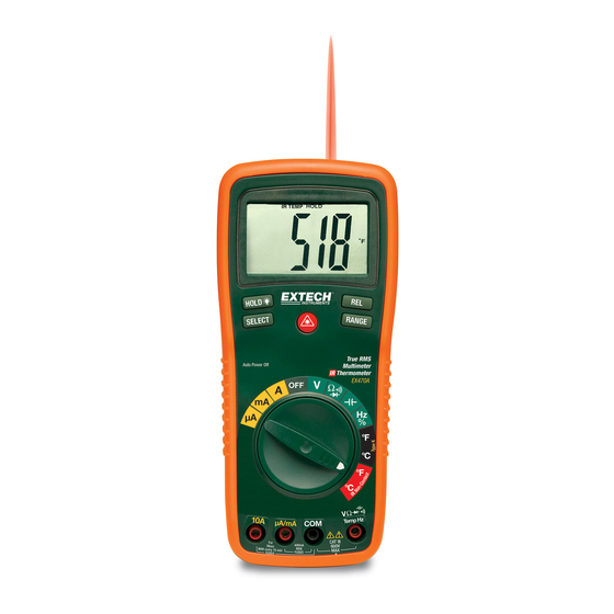
Page 5: Controls And Jacks
Controls and Jacks 1. IR Thermometer and laser pointer 2. 4000 count LCD display 3. HOLD and Backlight button 4. SELECT button 5. Function switch 6. mA, uA and A input jacks 7. COM input jack 8. Positive input jack 9. -
Page 6: Dc Voltage Measurements
Operating Instructions WARNING: Risk of electrocution. High-voltage circuits, both AC and DC, are very dangerous and should be measured with great care. 1. ALWAYS turn the function switch to the OFF position when the meter is not in use. 2. If “OL” appears in the display during a measurement, the value exceeds the range you have selected. -
Page 7: Ac Voltage Measurements
AC VOLTAGE MEASUREMENTS WARNING: Risk of Electrocution. The probe tips may not be long enough to contact the live parts inside some 240V outlets for appliances because the contacts are recessed deep in the outlets. As a result, the reading may show 0 volts when the outlet actually has voltage on it. -
Page 8: Ac Current Measurements
AC CURRENT MEASUREMENTS CAUTION: Do not make current measurements on the 20A scale for longer than 30 seconds. Exceeding 30 seconds may cause damage to the meter and/or the test leads. 1. Insert the black test lead banana plug into the negative COM jack. -
Page 9: Continuity Check
CONTINUITY CHECK WARNING: To avoid electric shock, never measure continuity on circuits or wires that have voltage on them. 1. Set the function switch to the green Ω position. 2. Insert the black lead banana plug into the negative COM jack. Insert the red test lead banana plug into the positive Ω... -
Page 10: Non-Contact Temperature Measurements
CONTACT TEMPERATURE MEASUREMENTS 1. Set the function switch to the black Type K ºC or ºF position. 2. Insert the Temperature Probe into the input jacks, making sure to observe the correct polarity. 3. Touch the Temperature Probe head to the part whose temperature you wish to measure. -
Page 11: Capacitance Measurements
CAPACITANCE MEASUREMENTS WARNING: To avoid electric shock, disconnect power to the unit under test and discharge all capacitors before taking any capacitance measurements. Remove the batteries and unplug the line cords. 1. Set the rotary function switch to the green position. - Page 12 AUTORANGING/MANUAL RANGE SELECTION When the meter is first turned on, it automatically goes into AutoRanging. This automatically selects the best range for the measurements being made and is generally the best mode for most measurements. For measurement situations requiring that a range be manually selected, perform the following: Press the RANGE key.
-
Page 13: Specifications
Specifications Function Range Resolution Accuracy DC Voltage 400mV 0.1mV ±(0.3% reading + 2 digits) 0.001V ±(0.5% reading + 2 digits) 0.01V 400V 0.1V 1000V ±(0.8% reading + 3 digits) AC Voltage 50 to 400Hz 400Hz to 1kHz 400mV 0.1mV ±(1.5% reading + 15 ±(2.5% reading + digits) 15digits) - Page 14 Function Range Resolution Accuracy ±(1.5% reading + 5 digits) Frequency 5.000Hz 0.001Hz 50.00Hz 0.01Hz 500.0Hz 0.1Hz 5.000kHz 0.001kHz ±(1.2% reading + 2 digits) 50.00kHz 0.01kHz 500.0kHz 0.1kHz 5.000MHz 0.001MHz ±(1.5% reading + 4 digits) 10.00MHz 0.01MHz Sensitivity: 0.8V rms min. @ 20% to 80% duty cycle and <100kHz; 5Vrms min @ 20% to 80% duty cycle and >...
-
Page 15: Maintenance
Maintenance WARNING: To avoid electrical shock, disconnect the meter from any circuit, remove the test leads from the input terminals, and turn OFF the meter before opening the case. Do not operate the meter with an open case. This MultiMeter is designed to provide years of dependable service, if the following care instructions are performed: 1. -
Page 16: Replacing The Fuses
The UL mark does not indicate that this product has been evaluated for the accuracy of its readings. Copyright © 2005 Extech Instruments Corporation All rights reserved including the right of reproduction in whole or in part in any form.
Need help?
Do you have a question about the 470 and is the answer not in the manual?
Questions and answers