
Related Manuals for Lantech CM-021-GB-II

Summary of Contents for Lantech CM-021-GB-II
- Page 1 Lantech CM-021-GB-II 10/100/1000Base-T to 1000Base-FX Switch Converter User Guide Rev.1.01 Aug 2008...
-
Page 3: Revision History
Revision History 10/100/1000Base-T to 1000Base-FX Switch Converter Document Date Revision Initials Release 1.00 Aug 18, 2008 First release E.C. Add dimension picture and modify the 1.01 Sep 11, 2008 E.C. power consumption value... -
Page 4: Table Of Contents
Content Introduce ........................1 ............................. 2 EATURES ........................4 ACKAGE ONTENTS Hardware Description ....................5 ..........................6 RONT ANEL ..........................6 ANEL ............................7 ORTS LED I .......................... 7 NDICATORS DIP- ..........................8 SWITCH Converters module Installation ................... 10 ............................. 11 ABLING Troubles shooting ....................... -
Page 5: Introduce
Introduce The Giga Fiber Converter has two types of module package; one is stand alone converter module. And another one is mounted in converter chassis converter module. The Giga Fiber Converter is a cost- effective solution for the converting 10/100/1000Base-TX (Auto MDI/MDIX) and pure 1000 Base-T to 1000Base-FX cabling. -
Page 6: Features
Features IEEE 802.3 10BASE-T IEEE 802.3u 100BASE-TX IEEE 802.3ab 1000BaseT, Standard IEEE 802.3z 1000BaseSX/LX standards IEEE 802.3x Flow Control and Back pressure Power (Green) UTP SPD: 1000Mbps /100Mbps Lnk/Act: UTP /FIBER LED Indicators FDX: UTP: Full-Duplex mode / Half-Duplex or Link down FIBER: Full-Duplex mode / Link down Fiber: Duplex SC/MINI GBIC 3.3V/ WDM RJ-45 Socket: CAT-5e (10/100/1000Mbps) Twisted Pair... - Page 7 Switch Store and Forward architecture 16Kbyte(Pure converter mode)/ Jumbo Frame 2Kbyte(Switch converter mode) Stand-alone (external adapter):DC 9V / 0.7A Power Power 4.3 Watts(max) Consumption Operating O℃ to 45℃ (32℉ to 113℉) Temperature Operating 10% to 90% Humidity Storage -40℃~70℃ environment Storage 10% to 90% Humidity...
-
Page 8: Package Contents
Package Contents Beware of which type of converter module that you have purchased. And, please refer to the package content list below to verify them against the checklist. Stand-alone converter module package contains following items. The Giga Fiber Converter AC-DC Power Adapter User Guide Rack mount ear (only for converter chassis) Compare the contents of your Converter with the standard checklist above. -
Page 9: Hardware Description
Hardware Description The Giga Fiber Converter dimension (L x W x H): 120mm x 85mm x 26mm... -
Page 10: Front Panel
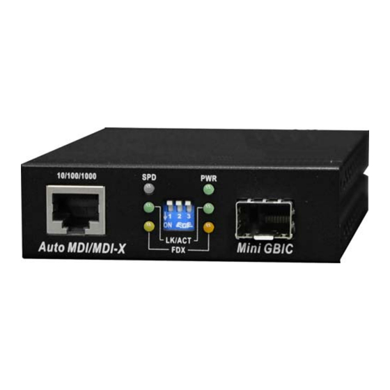
Front Panel 10/100/1000Base-T to 1000Base-FX converter module The Front Panel of the 10/100/1000Base-T to 1000Base-FX converter module consists of one Giga Fiber port, one copper Port (Auto MDI/MDIX), and 6 LED Indicators (SPD, LK/ACT, FDX, Fiber LK/ACT, FDX/COL, and PWR). (1) RJ-45 Port (3) DIP-Switch (2) LED... -
Page 11: Ports
Ports Copper Port (Auto MDI/MDIX) of 10/100/1000Base-T to 1000Base-FX converter module: The Ethernet ports will auto-sense for 10Base-T, 100Base-TX, or 1000Base-T connections. Auto MDI/MDIX means that you can connect to another Switch or workstation without changing non-crossover or crossover cabling. Fiber Port: This port is for 1000Base-FX connections. -
Page 12: Dip-Switch
Half-duplex mode or link down Green Link up LNK/ACT Blinks Transmitting (Fiber) Link down Amber Full-duplex mode FDX/COL (Fiber) Link down DIP-switch The DIP-switch is used to configure operation mode for LLF (Link Lost Forwarding) and operation mode for Copper/Fiber port. The default value of Dipswitch is OFF. 10/100/1000Base-T to 1000Base-FX converter module S/W No Status... - Page 13 And TP port should be forced at 1000M in this application. When DIP-Switch is in Switch Converter mode (off), the converter function is same as Switch Hub. [Note] a) Please don’t change the DIP-switch setting when copper or fiber port is transmitting or receiving data.
-
Page 14: Converters Module Installation
Converters module Installation This installation is only for mounted in converter chassis converter module. You can follow the steps below to install modular converters. A. Remove the blank bracket by rotating thumbscrew counterclockwise. Put the blank bracket aside, but don’t discard blanket bracket. B. -
Page 15: Cabling
Cabling Using four twisted-pair, Category 5e cabling for copper port connection. The cable between the converter and the link partner (switch, hub, workstation, etc.) must be less than 100 meters (328 ft.) long. Fiber segment using single-mode connector type must use 9/125 μm single-mode fiber cable. -
Page 16: Troubles Shooting
Troubles shooting Check the configuration DIP-switch. It must be setting in the same operation mode with the link partner. Select the proper Copper/Fiber cable to construct your network. The single-mode converter must use single-mode fiber cable. Please check that you are using the right cable.
Need help?
Do you have a question about the CM-021-GB-II and is the answer not in the manual?
Questions and answers