Duke 6/13 Installation, Operation, Parts & Maintenance Manual
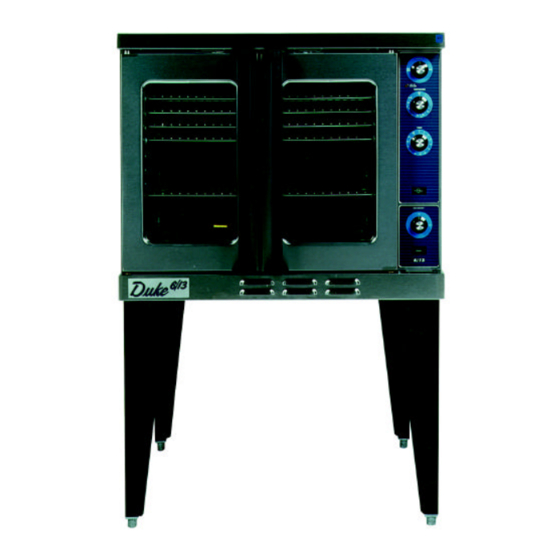
Gas fired convection oven
Hide thumbs
Also See for 6/13:
- Installation and operation manual (32 pages) ,
- Installation, operation, parts & maintenance manual (23 pages)
Table of Contents

Related Manuals for Duke 6/13


Summary of Contents for Duke 6/13
- Page 1 6/13 THE OVEN GAS FIRED CONVECTION OVEN Installation, Operation & Parts Maintenance Manual Part #152468 Rev. C DUKE MANUFACTURING CO. 2305 N. Broadway • St. Louis, MO 63102 800.735.3853 • 314.231.1130 • 314.231.5074 Fax www.dukemfg.com...
-
Page 2: Table Of Contents
INDEX INDEX PAGE PAGE 6/13 Gas Specifications “X” Controller “X” Motor/Element Side Installation Instructions A. Qualified Personnel “Z” & “ZX” Controller B. Delivery & Inspection “Z” & “ZX” Motor/Element Side C. Location of Oven D. Gas Piping Repair Parts List 41 - 42 E. -
Page 3: Limited Warranty
LIMITED WARRANTY Gas Convection Ovens DUKE MANUFACTURING CO . warrants to the original buyer that its Convection Ovens shall be free from defects in workmanship and materials for the period specified in this warranty. STANDARD PRODUCT WARRANTY PERIOD 1 Year, Limited Parts and Labor... -
Page 4: For Your Safety
WARNING: Improper installation, adjustment, alteration, service or maintenance can cause property damage, injury or death. Read the installation, operating and maintenance instructions thoroughly before installing or servicing this equipment. 6/13 GAS CONVECTION OVEN Specifications NATURAL GAS PROPANE GAS HEATING VALUE 1000 BTU 37.3 MJ/m... -
Page 5: B. Delivery & Inspection
B. Delivery and Inspection INSTALLATION INSTRUCTIONS Duke Manufacturing Co. does everything within its power to A. Qualified Personnel insure you received your oven in good condition. They are strapped down on heavy wooden skids and surrounded by These installation instructions are for the use of qualified heavy “tri-wall”... -
Page 6: D. Gas Piping
D. Gas Piping Each section of the 6/13-G Series Ovens (standard depth) is proper design of the gas supply system. rated at 40,000 BTU’s per hour (11.7 kW) or (deep depth) This oven has been tested and certified for use on gas 46,000 BTU’s per hour (13.5 kW). -
Page 7: F. Ventilation
E. Electrical Connections sufficient supply of make- up air. Ventilation hoods come in many sizes and capacities. Hood capacity is Your oven is supplied for connection to a 115 volt, expressed in cubic feet per minute (CFM). The total single phase grounded circuit. The electric motor, oven make-up and exhaust air required for the canopy hood lights, indicator lights and control circuits are connected should be about 22 CFM per oven section. -
Page 8: Leg Attachment
G. Oven Assembly Double Sections Before assembling and installing the oven, please check to • Secure the short legs to the bottom of the lower make sure that all necessary parts are present. In addition to section as described in previous section. the oven itself, there will also be legs, feet or casters, the flue/vent guard or draft hood &... -
Page 9: H. Adjustments Associated With Installation
Installation of the Vent H. Adjustments Associated with Installation • Ovens ordered for installation under a powered Each oven section and all its component parts have been canopy exhaust hood should have the flue tested thoroughly and inspected before your oven was guard in place. - Page 10 OPERATION INFORMATION All of this in addition to superior cooking results means the “6/13” Series of gas fired convection ovens is an outstanding value. In addition, lower NOx emissions The information in this section is intended for the use means it’s environmentally friendly. Please take the of qualified operating personnel.
- Page 11 Oven Controls — Electro-Mechanical “V” Controller • 1. The Power Switch - Controls power to ON or Cool Down Function. • 2. The Indicator Light - When lit indicates burners are operating. When the light goes out, the oven has reached its cooking temperature. •...
- Page 12 Oven Controls — Solid State Digital Controls “X” Controller • 1. The Power Switch - Controls power to ON or Cool Down function. • 2. The Indicator Light - When lit indicates burners are operating. When the light goes out, the oven has reached its cooking temperature.
-
Page 13: Timer Resolution
PROGRAMMING & OPERATION INSTRUCTIONS “COn:” and “CYC”. “X” CONTROLLER CANCEL • Press to exit. HOLD The fan can not be set to cycle if the mode is to be Timer Resolution used. The Timer displays time in two (2) different scales. From 0 Fan Speed Switch to 60 minutes, the timer is displayed in Minutes/Seconds The fan speed can be set to high or low speed by placing... - Page 14 Oven Controls — Solid State Digital Controls “Z” Controller • 1. The Power Switch - Controls power to ON or Cool Down function. • 2. The Indicator Light - When lit indicates burners are operating. When the light goes out, the oven has reached its cooking temperature.
-
Page 15: Time Dial
PROGRAMMING & OPERATING INSTRUCTIONS Time Dial “Z” CONTROLLER TIME dial sets time intervals for cooking. It is used in This controller provides five (5) automatic cooking chains either programmed or manual cooking. which the user can program. It will also a low non-automatic Temp Dial cooking and cook &... -
Page 16: Manual Cooking
PGM 1 PGM 2 cooking. Programs 1 and 2 provide the user with 6 events fan mode. allow the user to set up to 6 each, and programs 3, 4 and 5 provide 4 events each. The events to be performed during the cooking cycle, while PGM 3 PGM 4 PGM 5... - Page 17 EXAMPLE: MUFFINS EVENT 1 : Cook temp - 400°F, LOW fan speed, cycled fan, cook time = 4 minutes. Cycled, low fan allows the muffins to rise and skin over without being distorted by the air movement. EVENT 2 : Cook temp = 400°F, HIGH fan speed, continuous fan, cook time = 8 minutes.
- Page 18 Oven Controls — Solid State Digital Control “ZX” Controller with Rack Timer Capability • 1. The Power Switch - Controls power to ON or Cool Down function. • 2. The Indicator Light - When lit indicates burners are operating. When the light goes out, the oven has reached its cooking temperature.
- Page 19 Programming & Operating Instructions control is calling for heat. The display will show FAN CYC FAN CON when the cycled fan mode is selected and when “ZX” Controller CYCLE the continuous mode is selected. The indicator will light when the cycled fan is enabled. Timer Resolution Time Selector Buttons (1-5) The Timer displays time in two different scales.
-
Page 20: B. Door Adjustments
Once the oven is clean it can be wiped All 6/13 Series Convection Ovens (except model option Q) down with a light oil. have doors which are inter-connected so they operate... - Page 21 RACK • Pressing the selected button and then the CANCEL button within 3 seconds will “zero” the Timer at any time. • The alarm will sound at the end of the cooking cycle. CANCEL RACK Pressing the or selected button will cancel it.
- Page 22 B. General Guidelines for Operation when baking light products such as light cake batter or custard so the product will have time to set. Normally, 7 - 10 minutes with the oven OFF, These Guidelines are to assist you in obtaining the best performance from your oven: then finishing with the oven ON, will keep the product from rippling or being pulled by the fan.
- Page 23 PRODUCT °F °C COOK TIME RACKS TEMP TIME BEEF HAMBURGER PATTIES (3.3 OZ.) 8-10 MIN. MEAT LOAF 40-45 MIN. STEAMSHIP ROUND (80 LBS. QUART.) 2-3/4 HRS. F ROLLED BEEF ROAST (12-15 LBS.) 2-1/2 HRS. STANDING RIB ROAST (20 LBS. RARE) 2-3/4 HRS.
- Page 24 COOK & HOLD/ROAST & HOLD RECOMMENDED TIME & TEMPERATURE COOK HOLD HOLD TIME TOTAL PRODUCT QUANTITY COOK TIME TEMP TEMP MINIMUM TIME PRIME RIB 3 HRS. 1 HR. 4 HRS. BONE IN 200°F 140°F CAP OFF 3-1/4 HRS. 1-1/2 HRS. 4-3/4 HRS.
- Page 25 COOK & HOLD - ROAST & HOLD that the stored heat of the “COOK - ROAST” cycle has brought it to the desired degree of doneness. Control Options with COOK & HOLD - ROAST & HOLD feature include conveniences not found in standard control •...
-
Page 26: D. Thermostat Calibration
CAUTION: The turnbuckles and door switch are To Calibrate the Ovens located in a heated zone. Care should be taken to • Remove the thermostat knob by loosening the set avoid burns. screw and pull the knob forward. Take care not to rotate the thermostat stem, which will change the setting. - Page 27 E. Gas Pressure Regulation & Adjustment NOTE: It is important to check the gas pressure of any unit while ALL the equipment on that gas line is ON. This will tell you if you have a properly sized gas delivery system or if The gas pressure has been preset at the factory for the type of there is a problem with gas volume.
- Page 28 6/13 Door Assembly (typical)
-
Page 29: Double Stacked Ovens
Double Stacked Ovens Securing Double Stacked Ovens... -
Page 30: V" Controller Assembly
6/13 “V” Controller Assembly... -
Page 31: X" Controller Assembly
6/13 “X” Controller Assembly... -
Page 32: Z" Controller Assembly
6/13 “Z” Controller Assembly... -
Page 33: Zx" Controller Assembly
6/13 “ZX” Controller Assembly... -
Page 34: V" Controller
6/13 “V” CONTROLLER... -
Page 35: V" 208/240 Motor/Element Side
6/13 “V” 208/240 MOTOR/ELEMENT SIDE... - Page 36 6/13 “X” CONTROLLER...
- Page 37 6/13 “X” CONTROLLER...
- Page 38 6/13 “Z” & “ZX” CONTROLLER...
- Page 39 6/13 “Z” & “ZX” CONTROLLER...
- Page 40 Description Part # Description 153134 Mylar panel, “V” model, 2-button 153164 Baffle, 6/13 porcelain 153758 Mylar panel, “X” model 153738 Baffle, 6/13, stainless steel 153138 Mylar panel, “Z” model, 153451 Baffle ASM, burner 12-button 153056 Bearing, door hinge 153482 Mylar panel, “ZX” model 153093 Blower wheel, 9-3/8”...
Need help?
Do you have a question about the 6/13 and is the answer not in the manual?
Questions and answers