Table of Contents
Advertisement
Advertisement
Table of Contents

Related Manuals for Thermal Dynamics Drag-Gun


Summary of Contents for Thermal Dynamics Drag-Gun
- Page 1 Operating Manual For Models: Includes: • 100 VAC 50 Hz/110 VAC 60Hz • 12 Amp Power Supply • 120 VAC 50Hz • PCH-10 Torch with Leads • 120 VAC 60Hz • Work Cable with Clamp • 220 VAC 50Hz • Input Power Cable •...
- Page 3 The publisher does not assume and hereby disclaims any liabil- ity to any party for any loss or damage caused by any error or omission in the DRAG-GUN Plasma Cutter Operating Manual, whether such error results from negligence, accident, or any other cause.
-
Page 4: Table Of Contents
T T T T T ABLE OF CONTENTS ABLE OF CONTENTS ABLE OF CONTENTS ABLE OF CONTENTS ABLE OF CONTENTS 1: GENERAL INFORMATION ......................1 1.1 Notes, Cautions and Warnings ..................1 1.2 Important Safety Precautions ..................1 1.3 Publications ........................2 1.4 Note, Attention et Avertissement .................. -
Page 5: 1: General Information
1: GENERAL 1: GENERAL 1: GENERAL 1: GENERAL 1: GENERAL GASES AND FUMES INFORMA INFORMA TION TION INFORMA INFORMATION INFORMA TION TION Gases and fumes produced during the plasma cutting process can be dangerous and hazardous to your health. 1.1 Notes, Cautions and Warnings •... -
Page 6: Publications
• Install and maintain equipment according to NEC • To protect your eyes, always wear a welding hel- code, refer to item 9 in Subsection 1.3, Publications. met or shield. Also always wear safety glasses with side shields, goggles or other protective eye wear. •... -
Page 7: Note, Attention Et Avertissement
8. NFPA Standard 51, OXYGEN-FUEL GAS SYSTEMS FOR WELDING, CUTTING AND ALLIED PRO- AVERTISSEMENT CESSES, obtainable from the National Fire Protection Association, Batterymarch Park, Quincy, MA 02269 Toute procédure pouvant provoquer des blessures 9. NFPA Standard 70, NATIONAL ELECTRICAL CODE, de l’opérateur ou des autres personnes se trouvant obtainable from the National Fire Protection Asso- dans la zone de travail en cas de non-respect de la... - Page 8 procédés. Vous devez prendre soin lorsque vous coupez ou soudez tout métal pouvant contenir un INCENDIE ET EXPLOSION ou plusieurs des éléments suivants: antimoine cadmium mercure Les incendies et les explosions peuvent résulter des scories argent chrome nickel chaudes, des étincelles ou de l’arc de plasma. Le procédé arsenic cobalt plomb...
-
Page 9: Documents De Reference
• Use the shade of lens as suggested in the following 4. Norme ANSI Z87.1, PRATIQUES SURES POUR LA chart per ANSI/ASC Z49.1: PROTECTION DES YEUX ET DU VISAGE AU TRAVAIL ET DANS LES ECOLES, disponible de • Utilisez la nuance de lentille qui est suggèrée dans l’Institut Américain des Normes Nationales (Ameri- le recommendation qui suivent ANSI/ASC Z49.1: can National Standards Institute), 1430 Broadway,... - Page 10 14. Norme AWSF4.1 de l’Association Américaine de Soudage, RECOMMANDATIONS DE PRATIQUES SURES POUR LA PRÉPARATION À LA COUPE ET AU SOUDAGE DE CONTENEURS ET TUYAUX AYANT RENFERMÉ PRODUITS DANGEREUX , disponible auprès de la American Welding Society, 550 N.W. LeJeune Rd., Miami, FL 33126 15.
-
Page 11: Declaration Of Conformity
Rigorous testing is incorporated into the manufacturing process to ensure the manufactured product meets or exceeds all design specifications. Thermal Dynamics has been manufacturing products for more than 30 years, and will continue to achieve excellence in our area of manufacture. -
Page 12: Statement Of Warranty
The limited warranty periods for Thermal products shall be as follows (with the exception of XL Plus Series, CutMaster 80XL , Cougar and DRAG-GUN): A maximum of three (3) years from date of sale to an authorized distributor and a maximum of two (2) years from date of sale by such distributor to the Purchaser, and with the further limitations on such two (2) year period (see chart below). -
Page 13: Introduction
INTRODUCTION INTRODUCTION INTRODUCTION This manual contains descriptions, operating instructions and basic maintenance procedures for the DRAG-GUN Plasma Cutter. Read this manual thoroughly. A com- plete understanding of the characteristics and capabili- ties of this equipment will assure the dependable opera- tion for which it was designed. -
Page 14: General Product Description
1/8" (3.2 mm) of most metals. Everything you need to start cutting right away is in- cluded with the DRAG-GUN - power supply with built- in air compressor, pilot circuitry, all control circuitry, torch DRAG-GUN Plasma Cutter... -
Page 15: Dimensions
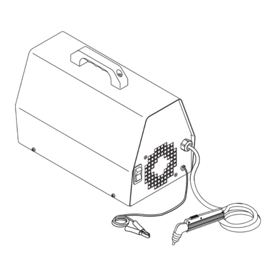
A-02005 Figure 2-4 Torch Dimensions Power Cable Figure 3-1 Front & Rear Panel Controls B. Rear Panel B. Rear Panel B. Rear Panel B. Rear Panel B. Rear Panel 1. Primary Input Power Cable Operating Manual 0-2682 DRAG-GUN Plasma Cutter... -
Page 16: Installation
D. Electrical Connections D. Electrical Connections NOTE The DRAG-GUN Cutter is available in various models. VAC is preset at the factory and cannot be changed, ex- Review Important Safety Precautions at the front cept with 208/230 VAC units (Refer to subsection 4.0-F of this manual to be sure that the selected location for procedure on changing voltage on unit). - Page 17 Always wear light cutting gloves when changing torch • 100VAC 50Hz/110VAC 60 Hz, single phase, with parts just after operating the Drag-Gun system. plug 2. Position the torch with the shield cup facing upward •...
-
Page 18: Operation
Standoff cutting - the torch tip is elevated from the workpiece slightly while cutting. Standoff height should be no more than 1/8" (3.2 mm); place your other hand underneath to steady. DRAG-GUN Plasma Cutter Operating Manual 0-2682... - Page 19 The DRAG-GUN is primarily designed for drag cutting, 2. Hold the torch on a slight angle to the workpiece with but in some instances can be used successfully for stand- the front of the tip at the edge of the workpiece (or off cutting.
-
Page 20: Cut Quality
Dross normally breaks off those shown. quite easily by simply scraping it off with a piece of metal. Material Gauge Inches per Minute Stainless Steel Galvanized Steel Aluminum Carbon Steel Figure 5-7 Cutting Speed Chart DRAG-GUN Plasma Cutter Operating Manual 0-2682... -
Page 21: Common Cutting Faults
The air filter element can be cleaned - remove it, blow air through it, and reinstall it. Operating Manual 0-2682 DRAG-GUN Plasma Cutter... -
Page 22: Maintenance
6.3 Torch Cleaning NOTE Even if precautions are taken to use only clean air with a Although the DRAG-GUN will cut using stand- torch, eventually the inside of the torch becomes coated off, this unit is primarily a drag-cutting machine. -
Page 23: Parts Replacement
7. Apply teflon thread sealant to the threads of the re- placement 90° nylon fitting and install in correct ori- entation as shown in Appendix I. Operating Manual 0-2682 DRAG-GUN Plasma Cutter... -
Page 24: Work Cable Replacement
8.1 Returns 8.1 Returns 8.1 Returns If a product must be returned for service, contact your authorized distributor or call 1-888-832-4250. Items re- turn to the manufacturer without proper authorization will not be accepted. DRAG-GUN Plasma Cutter Operating Manual 0-2682... -
Page 25: Parts Replacement
A. Complete Systems Includes Power Supply, PCH-10 70° Torch with Leads, Spare Consumable Parts, Input Power Cord, and Work Cable. DRAG-GUN 100V/50Hz 110V/60Hz, PCH-10 1-1111-3 DRAG-GUN 120V 50Hz, PCH-10, "CE" 1-1811-6 DRAG-GUN 120V 60Hz, PCH-10 1-1111-1 DRAG-GUN 220V 50Hz, PCH-10, "CE"... -
Page 26: Power Supply Replacement Parts
DRAG-GUN 208/230 60Hz, Power Cable, 16/3 w/molded plug 9-0014 ** Plug to be supplied by customer. ON/OFF Switch: DRAG-GUN Switch, DPST, 125V 15A w/RED NEON (non CSA) 9-0015 DRAG-GUN Switch, DPST, 22A, 125VAC, RED NEON (CSA) 9-0021 DRAG-GUN Switch, 16A, 250VAC, AMBER (or RED) NEON... - Page 27 To remove cover, unfasten: • 4 side panel screws • 2 handle screws • 2 end panel screws (BR2) (BR1) Chassis Rotation Direction Torch & Leads A-02337 Air Flow Direction Operating Manual 0-2682 DRAG-GUN Plasma Cutter...
-
Page 28: Torch Replacement Parts
Torch Switch Button Springs 9-6292 * To be replaced by Qualified Technician only. A-02360 HARDWARE #2-56 x 5/16" LG Phillips Pan Head #6 Internal Star Washer #6-32 x 3/16" Phillips Pan Head M.S., Zinc Plated DRAG-GUN Plasma Cutter Operating Manual 0-2682... -
Page 29: Appendix I: Cabling Details
Work Cable Faston Green Wire Ground Stud (Connect to mounting (from Primary Strain Relief Input Power Cable) (Install 5 1/2" from Faston) tab at bottom of Rectifier A-02653 Work Cable Replacement Input Power Cable Replacement Operating Manual 0-2682 DRAG-GUN Plasma Cutter... -
Page 30: Appendix Ii: Interconnecting Diagram
APPENDIX II: APPENDIX II: APPENDIX II: INTERCONNECTING DIAGRAM INTERCONNECTING DIAGRAM INTERCONNECTING DIAGRAM APPENDIX II: APPENDIX II: INTERCONNECTING DIAGRAM INTERCONNECTING DIAGRAM A-02277 DRAG-GUN Plasma Cutter Operating Manual 0-2682... - Page 31 NOTE: Use this diagram for all rev D (or later) units. Check the data tag on the unit for rev level. 12/01 8063 A-02277 Operating Manual 0-2682 DRAG-GUN Plasma Cutter...
-
Page 32: Appendix Iii: Interconnecting Diagram
INTERCONNECTING DIAGRAM INTERCONNECTING DIAGRAM INTERCONNECTING DIAGRAM APPENDIX III: APPENDIX III: INTERCONNECTING DIAGRAM INTERCONNECTING DIAGRAM NOTE: Use this diagram for all rev C units (or earlier). Check the data tag on the unit for rev level. DRAG-GUN Plasma Cutter Operating Manual 0-2682...
Need help?
Do you have a question about the Drag-Gun and is the answer not in the manual?
Questions and answers