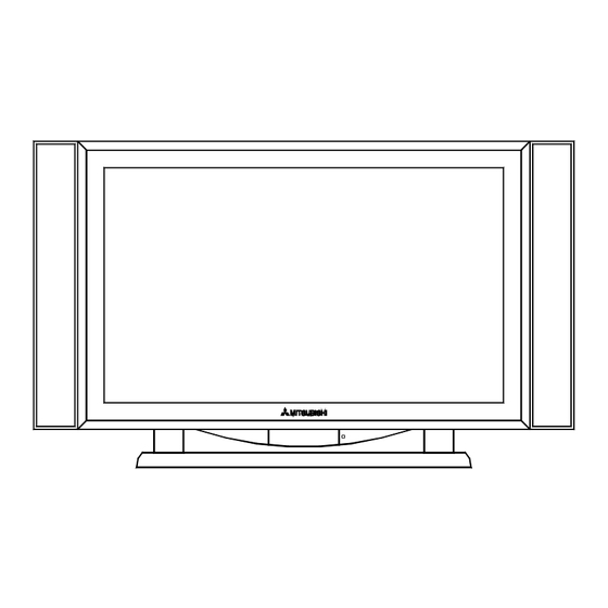
Advertisement
Quick Links
MITSUBISHI ELECTRIC
CAUTION:
Before servicing this chassis, it is important that the service person read the "PRODUCT SAFETY GUIDELINES"
contained in this manual.
• Pow e r
: AC 100-240V, 50/60Hz
350W Typical, 400W Maximum
• Displa y
Screen Size
: 42" Diagonal, Viewable
Aspect Ratio
: 16:9
Pixel Array
: 480 x 852
Pixel Pitch
: 1.08m m x 1.08mm
Horiz Sync Range : 15.5kHz - 68.7kHz
Vert Sync Range : 56Hz - 120Hz
• Inputs
Analog
: (2) Composite, (1) S-Video,
(1) Component & stereo audio
PC M onitor
: (1) Mini D-Sub 15 & stereo audio
MonitorLink™
: DVI, RS-232C, & stereo audio
RF
: NTSC VHF 2-13, UHF 14-69,
CATV 1-125
• Weight and dimensions shown are approximate.
• Design specifications are subject to change without notice.
MITSUBISHI DIGITAL ELECTRONICS AMERICA, INC.
SPECIFICATIONS
9351 Jeronimo Road, Irvine, CA 92618-1904
Copyright © 2004 Mitsubishi Digital Electronics America, Inc.
All Rights Reserved
Service
Manual
PLASMA DISPLAY PANEL
PD-4225S
• Outputs
Analog
: (1) Com posite & stereo audio
PC Monitor
: (1) Mini D-Sub 15
External Speaker
: 2 x 5 W atts into 8 ohms
• Form a ts
Video
: NTSC, 480i, 480p, 720p, 1080i
PC Monitor (4:3)
: VGA, SVGA, XGA, SXGA
PC Monitor (16:9)
: W -XGA
• Dim e nsions
w/ speakers & base : (W )49-5/8" (H)27-5/8" (D)10-7/8"
wo/ speakers & base : (W )40-3/4" (H)26" (D)4-3/8"
• W e ight
w/ speakers & base : 81.7 lbs
wo/ speakers & base : 65.2 lbs
2004
Advertisement

Summary of Contents for Mitsubishi Electric PD-4225S
-
Page 1: Service Manual
2004 Service MITSUBISHI ELECTRIC Manual PLASMA DISPLAY PANEL PD-4225S CAUTION: Before servicing this chassis, it is important that the service person read the "PRODUCT SAFETY GUIDELINES" contained in this manual. SPECIFICATIONS • Pow e r : AC 100-240V, 50/60Hz • Outputs... - Page 3 MODEL: PD-4225S CONTENTS PRODUCT SAFETY GUIDELINES ...................... 4 DISASSEMBLY PROCEDURES ......................5 ELECTRICAL ADJUSTMENTS......................6 REPLACEMENT PARTS ........................10 BLOCK DIAGRAMS .......................... 12 SCHEMATIC DIAGRAMS PCB MAIN DIAGRAMS PCB TUNER DIAGRAMS PCB FRONT DIAGRAMS PCB LAYOUT DIAGRAMS Page 3...
- Page 4 MODEL: PD-4225S PRODUCT SAFETY GUIDELINES 5. No lead or component should touch a receiving tube or a resistor rated at 1 IMPORTANT SAFETY NOTICE watt or more. Lead tension around protruding metal surfaces must be avoided. This manual was prepared for use only by properly trained audio-visual service 6.
- Page 5 MODEL: PD-4225S DISASSEMBLY PLATE A/V BACK COVER INNER 1. Screws marked (a) hold the Plate Assembly in place (Plate A/V). 2. Screws marked (b) connect Plate Assembly with Back Cover Assembly. 3. Screws marked with an arrow on the back of the PDP connect the Back Cover Assembly & Outer Assembly to the Main Frame.
-
Page 6: Electrical Adjustments
MODEL: PD-4225S ELECTRICAL ADJUSTMENTS Test Equipment • DMM • Signal Generator: RGB (VGA) - 1024x768, 60Hz, COMPONENT (YPbPr) - 1280x720p, 60Hz Notes • Do not attempt an adjustment if proper equipment is not available. • Because this is not a Hot chassis, no isolation transformer is required. However, the use of an isolation transformer will help protect test instruments. -
Page 7: Exploded View
MODEL: PD-4225S EXPLODED VIEW Page 7... -
Page 8: Replacement Parts List
MODEL: PD-4225S REPLACEMENT PARTS LIST Ref. No. Part Number Description 6348Q-E037T PDP-NP50C2MF01 (T/A REQ) 6871QDH051A PWB-DSP YDRV ASSY (PD4225) 6871QDH052A PWB-DSP YDRV ASSY (PD4225) 6871QCH025A PWB-PDP-DRV-CONTROL 6871QYH027A PWB-YSUS ASSY (PD4225) 6871QRH034A PWB-XRRT ASSY (PD4225) 6871QZH030A PWB-ZSUS (PD4225) 4980V00460A SUPPORTER,VERTICAL MN-42PZ40... -
Page 9: Block Diagrams
MODEL: PD-4225S BLOCK DIAGRAMS Page 9... - Page 10 MODEL: PD-4225S Page 10...
- Page 37 PD-4225S POWER PWB...


Need help?
Do you have a question about the PD-4225S and is the answer not in the manual?
Questions and answers