
Related Manuals for Code Alarm ca 2051


Summary of Contents for Code Alarm ca 2051
- Page 1 PROFESSIONAL SERIES Remote Keyless Entry Installation Guide ca 2051 ca2051 rev B. 2011 Audiovox Electronics Corporation. All rights reserved.
-
Page 2: Table Of Contents
Manual Feature Programming ..............10 Programming Feature Banks ..............11 Chirp Delete - User Accessible .............. 11 Feature Descriptions ................12 Transmitter Button Functions ............. 13 System Layout ..................14 ca2051 rev B. 2011 Audiovox Electronics Corporation. All rights reserved. -
Page 3: Before You Begin
DO NOT USE A TEST LIGHT, OR "COMPUTER SAFE PROBE" as these can set off air bags or damage vehicle computers. Technical Support (800) 421-3209 or go to http://techservices.codesystems.com ca2051 rev B. 2011 Audiovox Electronics Corporation. All rights reserved. -
Page 4: Wire Connection Guide
GROUND WHEN ARMED OUTPUT ( - ) BATTERY 12V ( + ) BROWN/BLACK HORN OUTPUT ( - ) YELLOW IGNITION INPUT ( + ) RED/WHITE TRUNK RELEASE OUTPUT ( - ) 6 Pin Door Lock Harness ca2051 rev B. 2011 Audiovox Electronics Corporation. All rights reserved. -
Page 5: 10 Pin Main Harness
Connect the WHITE wire to the parking light output wire. Negative switching Parking Lights: Connect the WHITE/RED wire to a good chassis ground. Connect the WHITE wire to the parking light output wire. ca2051 rev B. 2011 Audiovox Electronics Corporation. All rights reserved. - Page 6 Verification: This wire will register at positive voltage and register ground when the horn switch is pressed. Connect the BROWN/BLACK wire to the vehicle’s horn wire. This is a low current output, 200mA. ca2051 rev B. 2011 Audiovox Electronics Corporation. All rights reserved.
- Page 7 Locate the vehicle’s trunk release wire at the trunk release switch. Verification: This wire will register either positive voltage or ground when the trunk release is activated. This is a low current output, 200mA. ca2051 rev B. 2011 Audiovox Electronics Corporation. All rights reserved.
-
Page 8: Pin Door Lock Harness
Connect the VIOLET and the VIOLET/BLACK wires to a +12 volt battery source. The WHITE/BLACK and BROWN/BLACK wires are not required for this type of door lock/unlock system. ca2051 rev B. 2011 Audiovox Electronics Corporation. All rights reserved. -
Page 9: Additional Ports
It is suggested that the switch be mounted to the lower dash panel in the driver’s area within reach of the driver. ca2051 rev B. 2011 Audiovox Electronics Corporation. All rights reserved. -
Page 10: Set Up & Programming
2 - 4 chirps. NOTE: The system will remain in feature programming mode as long as the ignition is on, there is no time limit. To exit programming turn the IGNITION OFF. ca2051 rev B. 2011 Audiovox Electronics Corporation. All rights reserved. -
Page 11: Programming Feature Banks
Turn the ignition ON then OFF. Press and release the valet/programming button 3 times. The system will respond with 1 chirp for ON or 2 chirps for OFF. ca2051 rev B. 2011 Audiovox Electronics Corporation. All rights reserved. -
Page 12: Feature Descriptions
Lock and Unlock - Doors lock when ignition is turned on and unlock when ignition is turned off. Lock Only - Doors lock when ignition is turned on. Unlock Only - Doors unlock when ignition is turned off ca2051 rev B. 2011 Audiovox Electronics Corporation. All rights reserved. -
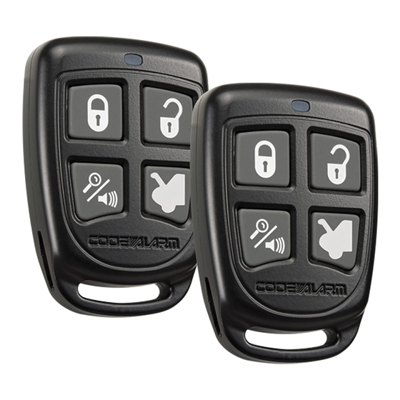
Page 13: Transmitter Button Functions
5 - Horn Output Timing: Control the minimum horn pulse time in milli seconds, some vehicle will require a longer pulse to activate the factory horn. 16mS 10mS 30mS 40mS 50mS Transmitter Button Functions ca2051 rev B. 2011 Audiovox Electronics Corporation. All rights reserved. - Page 14 B. 2011 Audiovox Electronics Corporation. All rights reserved.
- Page 15 B. 2011 Audiovox Electronics Corporation. All rights reserved.
-
Page 16: Customer Service
2. This device must accept any interference received, including any interference that may cause undesired operation. Warning! Changes or modifications not expressly approved by the party responsible for compliance could void the user’s authority to operate the equipment. ca2051 rev B. 2011 Audiovox Electronics Corporation. All rights reserved.