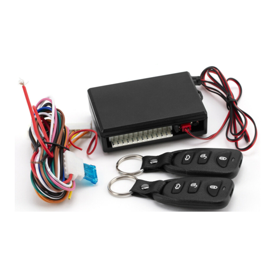
Summary of Contents for Code Alarm ca 1051
- Page 1 PROFESSIONAL SERIES Security and Keyless Entry Installation Guide ca 1051 ca1051 rev B. 2011 Audiovox Electronics Corporation. All rights reserved.
-
Page 2: Table Of Contents
Chirp Delete - User Accessible .............. 15 Dome Light Delay / Theater Dimming ............. 15 Feature Descriptions ................15 Transmitter Button Functions ............. 17 Security Trigger Zones ................. 17 System Layout ..................18 ca1051 rev B. 2011 Audiovox Electronics Corporation. All rights reserved. -
Page 3: Before You Begin
DO NOT USE A TEST LIGHT, OR "COMPUTER SAFE PROBE" as these can set off air bags or damage vehicle computers. Technical Support (800) 421-3209 or go to http://techservices.codesystems.com ca1051 rev B. 2011 Audiovox Electronics Corporation. All rights reserved. -
Page 4: Pin Main Harness
5 Pin Main Harness 6 Pin Input / Output Harness 2 Pin Door Lock Output Harness ca1051 rev B. 2011 Audiovox Electronics Corporation. All rights reserved. -
Page 5: Pin Main Harness
Route the BROWN siren output wire from the control module through the firewall and connect to the RED wire on the siren. NOTE: Be sure to loom the siren wires, and seal the grommet. ca1051 rev B. 2011 Audiovox Electronics Corporation. All rights reserved. - Page 6 Locate the vehicle’s trunk pin switch wire and connect to the BLUE wire. Verification: This wire when connected will register ground when the vehicle's trunk is opened. Connect the BLUE wire to the trunk pin. ca1051 rev B. 2011 Audiovox Electronics Corporation. All rights reserved.
- Page 7 Locate the vehicle’s trunk release wire at the trunk release switch. Verification: This wire will register either positive voltage or ground when the trunk release is activated. This is a low current output, 200mA. ca1051 rev B. 2011 Audiovox Electronics Corporation. All rights reserved.
-
Page 8: Pin Door Lock Output Harness
Connect the GREEN and BLUE wires shown in the diagram below. Negative Locks: GREEN (-) Lock Output Lock Vehicle Door Lock Control Relays Unlock BLUE (-) Unlock Output ca1051 rev B. 2011 Audiovox Electronics Corporation. All rights reserved. - Page 9 Reverse Polarity Locks: Fused +12 Volt Battery Souce GREEN (-) Lock Output Lock To Door Lock Motor Unlock Fused +12 Volt Battery Souce BLUE (-) Unlock Output To Door Lock Motor ca1051 rev B. 2011 Audiovox Electronics Corporation. All rights reserved.
- Page 10 (2) SPDT relays (not supplied). Multiplex Locks: Fused +12 Volt GREEN (-) Lock Output BLUE (-) Unlock Output Battery Source Resistor Lock Vehicle Door Lock Control Relays Unlock ca1051 rev B. 2011 Audiovox Electronics Corporation. All rights reserved.
- Page 11 BLUE wires shown in the diagram below using (2) SPDT relays (not supplied). Fused +12 Volt Battery Source Door Lock GREEN (-) Lock Output Actuator Chassis Ground Fused +12 Volt Battery Source BLUE (-) Unlock Output Chassis Ground ca1051 rev B. 2011 Audiovox Electronics Corporation. All rights reserved.
-
Page 12: Additional Ports
Select a solid mounting surface for the alarm module inside the passenger compartment (behind the dash), and mount the sensor using cable ties. Refer to feature programming for on-board shock sensor adjustment. ca1051 rev B. 2011 Audiovox Electronics Corporation. All rights reserved. -
Page 13: Set Up & Programming
2 - 4 chirps. NOTE: The system will remain in feature programming mode as long as the ignition is on, there is no time limit. To exit programming turn the IGNITION OFF. ca1051 rev B. 2011 Audiovox Electronics Corporation. All rights reserved. -
Page 14: Transmitter Programming
Press and release to lock in the change, the system will exit programming and give 1 long chirp to confirm. This step must be completed to properly program the shock senor. ca1051 rev B. 2011 Audiovox Electronics Corporation. All rights reserved. -
Page 15: Programming Feature Banks
The system will only sound the arm/disarm chirps upon a second press of the lock/unlock buttons. OFF - normal arm/disarm chirps upon the first press of lock/unlock. ca1051 rev B. 2011 Audiovox Electronics Corporation. All rights reserved. - Page 16 Lock and Unlock - Doors lock when ignition is turned on and unlock when ignition is turned off. Lock Only - Doors lock when ignition is turned on. Unlock Only - Doors unlock when ignition is turned off. ca1051 rev B. 2011 Audiovox Electronics Corporation. All rights reserved.
-
Page 17: Transmitter Button Functions
If the security system has been triggered the LED will flash one of the patterns below indicating the zone. LED FLASHES TRIGGER ZONE 2 Flashes Hood / Trunk Input 3 Flashes Door Input 4 Flashes Shock Sensor 5 Flashes Ignition Input ca1051 rev B. 2011 Audiovox Electronics Corporation. All rights reserved. - Page 18 B. 2011 Audiovox Electronics Corporation. All rights reserved.
- Page 19 B. 2011 Audiovox Electronics Corporation. All rights reserved.
-
Page 20: Customer Service
2. This device must accept any interference received, including any interference that may cause undesired operation. Warning! Changes or modifications not expressly approved by the party responsible for compliance could void the user’s authority to operate the equipment. ca1051 rev B. 2011 Audiovox Electronics Corporation. All rights reserved.


Need help?
Do you have a question about the ca 1051 and is the answer not in the manual?
Questions and answers