Table of Contents
Advertisement
Quick Links
Advertisement
Table of Contents

Related Manuals for Asus NCCH-DL


Summary of Contents for Asus NCCH-DL
- Page 1 NCCH-DL User Guide...
- Page 2 Product warranty or service will not be extended if: (1) the product is repaired, modified or altered, unless such repair, modification of alteration is authorized in writing by ASUS; or (2) the serial number of the product is defaced or missing.
-
Page 3: Table Of Contents
Contents Notices ................... vi Safety information ................. vii About this guide ................viii NCCH-DL specifications summary ..........x Chapter 1: Product introduction 1.1 Welcome! ................1-1 1.2 Package contents ............... 1-1 1.3 Special features ..............1-2 1.3.1 Product highlights ..........1-2 1.3.2... - Page 4 4.1 Managing and updating your BIOS ........4-1 4.1.1 Creating a bootable floppy disk ......4-1 4.1.2 AwardBIOS Flash Utility ........4-2 4.1.3 ASUS EZ Flash Utility ..........4-6 4.2 BIOS Setup program ............4-7 4.2.1 BIOS menu screen ..........4-8 4.2.2 Menu bar ..............4-8 4.2.3...
- Page 5 Boot Device Priority ..........4-36 4.6.2 Hard Disk Boot Priority ........4-37 4.6.3 Removable Device Priority ........4-37 4.6.4 Boot Settings Configuration ......... 4-38 4.6.5 Security ..............4-39 4.7 Exit menu ................. 4-41 Appendix: Reference information A.1 NCCH-DL block diagram ............ A-1...
-
Page 6: Notices
Notices Federal Communications Commission Statement This device complies with Part 15 of the FCC Rules. Operation is subject to the following two conditions: • This device may not cause harmful interference, and • This device must accept any interference received including interference that may cause undesired operation. -
Page 7: Safety Information
Safety information Electrical safety • To prevent electrical shock hazard, disconnect the power cable from the electrical outlet before relocating the system. • When adding or removing devices to or from the system, ensure that the power cables for the devices are unplugged before the signal cables are connected. -
Page 8: About This Guide
About this guide This user guide contains the information you need when installing and configuring the motherboard. How this guide is organized This manual contains the following parts: • Chapter 1: Product introduction This chapter describes the features of the motherboard. It includes brief descriptions of the special attributes of the motherboard and the new technology it supports. -
Page 9: Conventions Used In This Guide
Where to find more information Refer to the following sources for additional information and for product and software updates. 1. ASUS Websites The ASUS websites worldwide provide updated information on ASUS hardware and software products. Refer to the ASUS contact information. 2. Optional Documentation Your product package may include optional documentation, such as warranty flyers, that may have been added by your dealer. -
Page 10: Ncch-Dl Specifications Summary
NCCH-DL specifications summary ® Support for dual Intel Xeon™ Processors up to 3.4 GHz with Hyper-Threading Technology 1MB L2 cache (for 800 MHz) 512 KB L2 chache (for 533 MHz) ® Chipset Northbridge: Intel E82875P Memory Controller Hub (MCH) ®... - Page 11 NCCH-DL specifications summary Internal connectors Floppy disk drive connector Serial ATA connectors IDE connectors GAME/MIDI connector IEEE 1394 connector Chassis intrusion connector Serial ATA RAID connectors Backplane SMBus connector Power connectors Hard disk activity LED connector Front panel audio connector...
-
Page 13: Chapter 1: Product Introduction
Chapter 1 This chapter describes the features of the motherboard. It includes brief explanations of the special attributes of the motherboard and the new technology it supports. Product introduction... - Page 14 Chapter summary Welcome! ............1-1 Package contents .......... 1-1 Special features ..........1-2 ASUS NCCH-DL motherboard...
-
Page 15: Welcome
® Thank you for buying the ASUS NCCH-DL motherboard! The ASUS NCCH-DL motherboard delivers a host of new features and latest technologies making it another standout in the long line of ASUS quality motherboards! Before you start installing the motherboard, and hardware devices on it, check the items in your package with the list below. -
Page 16: Special Features
Special features 1.3.1 Product highlights Latest processor technology ® The motherboard supports dual Intel Xeon™ Processors via 604-pin surface mount ZIF sockets. The processor has 1MB L2 cache, includes an 800/533 MHz system bus, and features the Intel Hyper-Threading Technology that allows up to 3.4+ GHz core frequencies. -
Page 17: Channel Audio Feature
ASUS POST Reporter™ The motherboard offers a new exciting feature called the ASUS POST Reporter™ to provide friendly voice messages and alerts during the Power-On Self-Tests (POST) informing you of the system boot status and causes of boot errors, if any. -
Page 18: Value-Added Solutions
ASUS Update This utility allows you to update the motherboard BIOS through a user-friendly interface. Connect to the Internet then to the ASUS FTP site nearest you to obtain the latest BIOS version for your motherboard. Chapter 1: Product introduction... -
Page 19: Chapter 2: Hardware Information
Chapter 2 This chapter describes the hardware setup procedures that you have to perform when installing system components. It includes details on the switches, jumpers, and connectors on the motherboard. Hardware information... - Page 20 Chapter summary Before you proceed ........2-1 Motherboard installation ....... 2-3 Central Processing Unit (CPU) ....2-11 System memory ........... 2-15 Expansion slots ........... 2-18 Jumpers ............2-21 Connectors ........... 2-25 ASUS NCCH-DL motherboard...
-
Page 21: Before You Proceed
(SB_PWR1) lights up to indicate that the system is ON, in sleep mode, or in soft-off mode. This is a reminder that you should shut down the system and unplug the power cable before removing or plugging in any motherboard component. SB_PWR1 Standby Powered Power NCCH-DL Standby power LED ASUS NCCH-DL motherboard... - Page 22 Incorrect AGP Card Correct AGP Card LED1 CPU voltage not stable No detected CPU problem CPU FSB not identical WARN_CPU1 NCCH-DL Warning LEDs No CPU installed No detected CPU problem No CPU on socket CPU1 CPU types mismatched Chapter 2: Hardware information...
-
Page 23: Motherboard Installation
Place ten (10) screws into the holes indicated by solid black circles to secure the motherboard to the chassis. Do not overtighten the screws! Doing so may damage the motherboard. Place this side towards the rear of the chassis ASUS NCCH-DL motherboard... -
Page 24: Support Plates For Motherboard
2.2.3 Support plates for motherboard For additional protection from motherboard breakage due to the weight of the CPU heatsinks, your motherboard package comes with a CPU heatsink support kit that consists of: • 2 x metal support plates • 1 x contour sheet •... - Page 25 4. Use a plier to attach four nuts to the bolts on the metal support plate. 5. Align a rubber pad to the rectagular mark on the center of the plate, then press to attach. 6. Remove the adhesive label underneath a plate. ASUS NCCH-DL motherboard...
- Page 26 7. Carefully align and place the plate on a rectangular cut on the contour sheet. Make sure that the metal support plates fit perfectly to the rectangular cuts on the contour sheet; otherwise, the CPU heatsink screws would not align to the metal nuts. 8.
- Page 27 Make sure that the CPU heatsink holes on the motherboard perfectly match the metal nuts on the support plates; otherwise, you can not install the CPU heatsinks properly. 10. Secure the motherboard with 10 screws. Refer to section “2.2.2 Screw holes” for illustration. ASUS NCCH-DL motherboard...
-
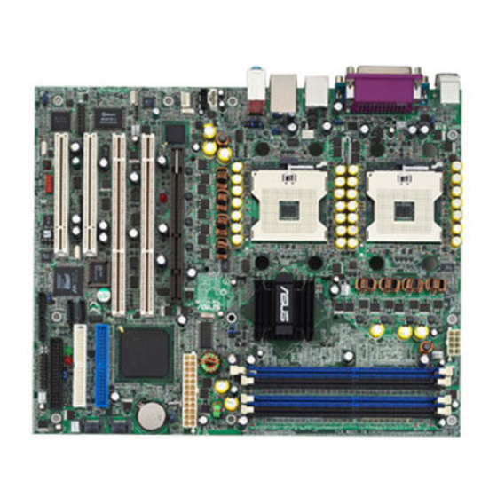
Page 28: Motherboard Layout
2.2.4 Motherboard layout 25cm (9.8in) ATX12V1 PS/2KBMS T: Mouse B: Keyboard KBPWR1 REAR_FAN1 COM1 CPU_FAN1 FM_CPU1 CPU1 CPU_FAN2 COM2 USBPW12 FM_CPU2 Bottom: Top: T:USB4 1394 B:USB3 Intel USB2.0 Top: 82875P T: USB1 RJ-45 B: USB2 Canterwood USBPW34 Top:Line In CPU2 Center:Line Out Below:Mic In FP_AUDIO1... -
Page 29: Layout Contents
6. Chassis intrusion connector (4-1 pin CHASSIS1) 2-29 7. Serial ATA RAID connectors (7-pin SATA_RAID1/2) 2-30 8. Backplane SMBus connector (6-1 pin BPSMB1) 2-30 9. Power connectors (24-pin ATXPWR1, 8-pin ATX12V1) 2-31 10. Hard disk activity LED connector (2-pin IDELED1) 2-31 ASUS NCCH-DL motherboard... - Page 30 Internal connectors (continued) 11. Front panel audio connector (10-1 pin FP_AUDIO1) 2-32 12. Internal audio connectors (4-pin CD1, AUX1, MODEM1) 2-32 13. CPU and system fan connectors (3-pin CPU_FAN1/2, REAR_FAN1/2, FRNT_FAN1/2) 2-33 14. System panel connector (20-pin PANEL) 2-33 - System Power LED (3-pin PLED) 2-34 - Message LED (2-pin MLED) 2-34...
-
Page 31: Central Processing Unit (Cpu)
Processor in the 604-pin package. Intel Xeon Gold Arrow NCCH-DL Socket 604 2.3.2 Installing the CPU Note in the above illustration that the CPU has a gold triangular mark on one corner. This mark indicates the processor Pin 1 that should match a specific corner of the CPU socket. - Page 32 Incorrect installation of the CPU into the socket may bend the pins and severely damage the CPU! Follow these steps to install a CPU. 1. Locate the 604-pin ZIF sockets on the motherboard. Flip up the socket lever and push it all the way to the other side.
-
Page 33: Installing The Cpu Heatsink And Fan
To install the CPU heatsink and fan: 1. Place the heatsink on top of the installed CPU, making sure that the four screws on the heatsink align with the nuts on the support plate. ASUS NCCH-DL motherboard 2-13... - Page 34 2. Use a Phillips screwdriver to tighten the four heatsink screws in a diagonal sequence. 3. Connect the fan cable to the 4-pin connector labeled CPU_FAN1. CPU1 fan connector (CPU_FAN1) 4. Repeat steps 1 to 3 to install the other heatsink if you have installed a second CPU, then connect the fan cable to the 4-pin connector labeled CPU_FAN2.
-
Page 35: System Memory
The motherboard comes with four Double Data Rate (DDR) Dual Inline Memory Module (DIMM) sockets. The following figure illustrates the location of the DDR DIMM sockets. NCCH-DL 184-pin DDR DIMM sockets 2.4.2 Memory configurations You may install unbuffered ECC or non-ECC 64MB, 128MB, 256MB, 512MB, and 1GB DDR DIMMs into the DIMM sockets using the recommended memory configurations. - Page 36 800 MHz PC3200 400 MHz 533 MHz PC2700 333 MHz 400 MHz PC2100 266 MHz Obtain DDR DIMMs only from ASUS qualified vendors for better system performance. Visit the ASUS website (www.asus.com) for the latest QVL. 2-16 Chapter 2: Hardware information...
-
Page 37: Installing A Dimm
DIMM. Support the DIMM lightly with your fingers when pressing the retaining clips. The DIMM might get damaged when it flips out with extra force. 2. Remove the DIMM from the socket. ASUS NCCH-DL motherboard 2-17... -
Page 38: Expansion Slots
Expansion slots In the future, you may need to install expansion cards. The motherboard has two 64-bit PCI-X slots, two 32-bit PCI slots, and an AGP slot. The following sub-sections describe the slots and the expansion cards that they support. Make sure to unplug the power cord before adding or removing expansion cards. -
Page 39: Standard Interrupt Assignments
When using PCI cards on shared slots, ensure that the drivers support “Share IRQ” or that the cards do not need IRQ assignments. Otherwise, conflicts will arise between the two PCI groups, making the system unstable and the card inoperable. ASUS NCCH-DL motherboard 2-19... -
Page 40: Pci/Pci-X Slots
Install only +0.8V or +1.5V AGP cards. This motherboard does not support 3.3V AGP cards. The WARN1 LED lights up if you installed an incorrect AGP card. Refer to page 2-2 for the LED location. Keyed for 1.5V NCCH-DL Accelerated Graphics Port (AGP) 2-20 Chapter 2: Hardware information... -
Page 41: Jumpers
+5VSB lead, and a corresponding setting in the BIOS. Refer to Chapter 4 for information. KBPWR1 +5VSB (Default) NCCH-DL Keyboard power setting 2. RAID controller setting (3-pin RAID_EN1) ® This jumper allows you enable or disable the Promise PDC20319 RAID controller. -
Page 42: Usb Device Wake-Up (3-Pin Usbpw12, Usbpw)
(Default) USBPW34 +5VSB (Default) NCCH-DL USB device wake up 1. The USB device wake-up feature requires a power supply that can provide 500mA on the +5VSB lead for each USB port. Otherwise, the system would not power up. 2. The total current consumed must NOT exceed the power supply capability (+5VSB) whether under normal condition or in sleep mode. - Page 43 CLRTC1 Normal Clear CMOS (Default) NCCH-DL Clear RTC RAM Except when clearing the RTC RAM, never remove the cap on CLRTC jumper default position. Removing the cap will cause system boot failure! ASUS NCCH-DL motherboard 2-23...
-
Page 44: Cpu Fan Pin Selection (3-Pin Fm_Cpu1, Fm_Cpu)
4-pin Fan (DC Mode) (Force to 12V) NCCH-DL USB CPU fan pin selection 7. IEEE 1394 setting (3-pin 1394_EN) These jumpers allow you to enable or disable the onboard IEEE 1394 controller. Set to pins 1-2 to activate the 1394 feature. -
Page 45: Connectors
6. Line Out port. This Line Out (lime) port connects a headphone or a speaker. In 6-channel mode, the function of this port becomes Front Speaker Out. 7. Microphone port. This Mic (pink) port connects a microphone. In 6-channel mode, the function of this port becomes Bass/Center. ASUS NCCH-DL motherboard 2-25... - Page 46 Headset/ Port 2-channel 4-channel 6-channel Light blue Line In Rear Speaker Out Rear Speaker Out Lime Line Out Front Speaker Out Front Speaker Out Pink Mic In Mic In Bass/Center 8. USB 2.0 ports 3 and 4. These 4-pin Universal Serial Bus (USB) ports are available for connecting USB 2.0 devices.
-
Page 47: Internal Connectors
PIN 1 NOTE: Orient the red markings on the floppy ribbon cable to PIN 1. NCCH-DL Floppy disk drive connector 2. Serial ATA connectors (7-pin SATA1, SATA2) These next generation connectors support the thin Serial ATA cables for Serial ATA hard disks. The current Serial ATA interface allows up to 150 MB/s data transfer rate, faster than the standard parallel ATA with 133 MB/s (Ultra ATA/133). -
Page 48: Game/Midi Connector (16-1 Pin Game)
NOTE: Orient the red markings (usually zigzag) on the IDE ribbon cable to pin 1. NCCH-DL IDE connectors 4. GAME/MIDI connector (16-1 pin GAME1) This connector supports a GAME/MIDI module. Connect the GAME/ MIDI cable to this connector. The GAME/MIDI port on the module connects a joystick or a game pad for playing games, and MIDI devices for playing or editing audio files. - Page 49 By default, the pins labeled “Chassis Signal” and “Ground” are shorted with a jumper cap. If you wish to use the chassis intrusion detection feature, remove the jumper cap from the pins. CHASSIS1 (Default) NCCH-DL Chassis intrusion connector ASUS NCCH-DL motherboard 2-29...
- Page 50 RAID feature. Refer to page 4-17 fro information. SATA_RAID1 SATA_RAID2 SATA_RAID3 SATA_RAID4 NCCH-DL SATA RAID connectors 8. Backplane SMBus connector (6-1 pin BPSMB1) This connector allows you to connect SMBus (System Management Bus) devices. Devices communicate with an SMBus host and/or other SMBus devices using the SMBus interface.
-
Page 51: Power Connectors (24-Pin Atxpwr1, 8-Pin Atx12V)
For power supply with 20-pin power connector NCCH-DL ATX power connectors 10. Hard disk activity LED connector (2-pin IDELED1) This connector supplies power to the hard disk activity LED. The read or write activities of any device connected to the primary or secondary IDE connector cause this LED to light up. - Page 52 +5VA MICPWR AGND MIC2 NCCH-DL Front panel audio connector 12. Internal audio connectors (4-pin CD1, AUX1, MODEM1) These connectors allow you to receive stereo audio input from sound sources such as a CD-ROM, TV tuner, or MPEG card. The MODEM connector allows the onboard audio to interface with a voice modem card with a similar connector.
- Page 53 These are not jumpers! DO NOT place jumper caps on the fan connectors! 14. System panel connector (20-pin PANEL1) This connector accommodates several system front panel functions. KEYLOCK SPKR PLED RESET MLED PWR_SW NCCH-DL System panel connector ASUS NCCH-DL motherboard 2-33...
- Page 54 • System Power LED (3-pin PLED) This lead connects to the system power LED. The LED lights up when you turn on the system power, and blinks when the system is in sleep mode. • Message LED (2-pin MLED) This lead connects to the message LED cable on the front panel and indicates the booting status.
-
Page 55: Chapter 3: Powering Up
Chapter 3 This chapter describes the power up sequence and gives information on the BIOS beep codes. Powering up... - Page 56 Chapter summary Starting up for the first time ......3-1 Vocal POST Messages ........3-2 Powering off the computer ......3-4 ASUS NCCH-DL motherboard...
-
Page 57: Starting Up For The First Time
Motherboard timer not operational Keyboard controller BAT test error General exception error Display memory error CMOS shutdown register read/write error 7. At power on, hold down <Delete> to enter BIOS Setup. Follow the instructions in Chapter 4. ASUS NCCH-DL motherboard... -
Page 58: Vocal Post Messages
Vocal POST Messages This motherboard includes the Winbond speech controller to support a special feature called the ASUS POST Reporter™. This feature gives you vocal POST messages and alerts to inform you of system events and boot status. In case of a boot failure, you will hear the specific cause of the problem. - Page 59 CPU voltage out of range • Check your power supply and make sure it is not defective. • Call ASUS technical support for assistance. See the “ASUS contact information.” System completed Power-On Self Test • No action required Computer now booting to operating •...
-
Page 60: Powering Off The Computer
Powering off the computer 3.3.1 Using the OS shut down function ® ® If you are using Windows 2000 Professional or Windows 2000 Server: 1. Click the Start button then click Shut Down... 2. Make sure that the Shut down option button is selected, then click the OK button to shut down the computer. -
Page 61: Chapter 4: Bios Setup
Chapter 4 This chapter tells how to change system settings through the BIOS Setup menus. Detailed descriptions of the BIOS parameters are also provided. BIOS setup... - Page 62 Chapter summary Managing and updating your BIOS ....4-1 BIOS Setup program ........4-7 Main menu ............ 4-10 Advanced menu ........... 4-16 Power menu ..........4-30 Boot menu ............ 4-36 Exit menu ............4-41 ASUS NCCH-DL motherboard...
-
Page 63: Managing And Updating Your Bios
From the Menu bar, click File > Format. e. Select “Create an MS-DOS Startup Disk” in the Format Options field, then click Start. 2. Copy the original (or the latest) motherboard BIOS to the bootable floppy disk. ASUS NCCH-DL motherboard... -
Page 64: Awardbios Flash Utility
Updating the BIOS To update the BIOS using this utility. 1. Download the latest BIOS file from the ASUS web site. Rename the file to *.BIN and save it to a floppy disk. Save only the updated BIOS file in the floppy disk to avoid loading the wrong BIOS file. - Page 65 6. Type the BIOS file name in the File Name to Program field, then press <Enter>. AwardBIOS Flash Utility for ASUS V1.05 (C) Phoenix Technologies Ltd. All Rights Reserved For Canterwood - NCCH-DL DATE: 06/01/2004 Flash Type - SST 49LF004A/B /3.3V File Name to Program : 1001.bin...
-
Page 66: Saving The Current Bios File
9. The utility displays a Flashing Complete message indicating that you have successfully flashed the BIOS file. Press <F1> to restart the system. AwardBIOS Flash Utility for ASUS V1.05 (C) Phoenix Technologies Ltd. All Rights Reserved For Canterwood - NCCH-DL DATE: 06/01/2004 Flash Type - SST 49LF004A/B /3.3V... - Page 67 3. Type a filename for the current BIOS file in the Save current BIOS as field, then press <Enter>. AwardBIOS Flash Utility for ASUS V1.05 (C) Phoenix Technologies Ltd. All Rights Reserved For Canterwood - NCCH-DL DATE: 06/01/2004 Flash Type - SST 49LF004A/B /3.3V File Name to Program : 1001.bin...
-
Page 68: Asus Ez Flash Utility
4.1.3 ASUS EZ Flash Utility he ASUS EZ Flash feature allows you to update the BIOS without having to go through the long process of booting from a floppy disk and using a DOS-based utility. The EZ Flash utility is built-in the BIOS chip so it is accessible by pressing <Alt>... -
Page 69: Bios Setup Program
Because the BIOS software is constantly being updated, the following BIOS setup screens and descriptions are for reference purposes only, and may not exactly match what you see on your screen. ASUS NCCH-DL motherboard... -
Page 70: Bios Menu Screen
4.2.1 BIOS menu screen Menu bar Menu items General help Select Menu Time (hh:mm:ss) 11: 10 : 30 Date (mm:dd:yy) Wed, Jun 30 2004 Item Specific Help Legacy Diskette A [1.44M, 3.5 in.] Floppy 3 Mode Support [Disabled] Change the day, month, year and century. -
Page 71: Navigation Keys
Press Up/Down arrow keys or PageUp/PageDown keys to display the other items on the screen. 4.2.7 Pop-up window Select an item in the menu, then press Enter to display a pop-up window with the configuration options for that item. ASUS NCCH-DL motherboard... -
Page 72: Main Menu
Main menu When you enter the BIOS Setup program, the Main menu screen appears giving you an overview of the basic system information. Refer to section “4.2.1 BIOS menu screen” for information on the menu screen items and how to navigate through them. Select Menu Time (hh:mm:ss) 11: 10 : 30... -
Page 73: Primary Ide Master
If no drive is installed or if you are removing a drive and not replacing it, select [None]. Configuration options: [None] [Auto] [Manual] Access Mode [Auto] Allows selection of the sector addressing mode. The default [Auto] allows automatic detection of an IDE drive. Configuration options: [CHS] [LBA] [Large] [Auto] ASUS NCCH-DL motherboard 4-11... - Page 74 Most of the IDE drive information items are grayed out when the items Primary IDE Master and Access Mode are set to [Auto]. If you wish to manually configure the IDE drive items, set the Primary IDE Master to [Manual], and the Access Mode to [CHS]. PIO Mode [Auto] Sets the PIO mode for the IDE drive.
- Page 75 Enter. Capacity [xxxxx MB] Displays the auto-detected hard disk capacity. The value is not user- configurable. Cylinder Shows the number of the hard disk cylinders. Head Shows the number of the hard disk read/write heads. ASUS NCCH-DL motherboard 4-13...
-
Page 76: Primary Ide Slave
Precomp Displays the precompressed volumes on the hard disk, if any, on the motherboard. Landing Zone Displays the drive’s maximum usable capacity as calculated by the BIOS based on the drive information you entered. Sector Shows the number of sectors per track. Transfer Mode Shows the data transfer mode if the IDE hard disk drive supports the feature. -
Page 77: Third Ide Master
The items Third IDE Master and Fourth IDE Master appear only if you set the On-Chip Serial ATA item in SATA Configuration menu to either [Auto] or [Enhanced Mode]. See page 4-25 for information. ASUS NCCH-DL motherboard 4-15... -
Page 78: Advanced Menu
Advanced menu The Advanced menu items allow you to change the settings for the CPU, memory, chipset, and other system devices. Take caution when changing the settings of the Advanced menu items. Incorrect field values may cause the system to malfunction! Select Menu Advanced BIOS Features CPU Configuration... -
Page 79: Cpu Configuration
Set this item to [Enabled] if you are using an operating system that is optimized for Hyper-Threading Technology, such as Windows XP or Linux kernel later than version 2.4. Otherwise, set this item to [Disabled]. Configuration options: [Disabled] [Enabled] ASUS NCCH-DL motherboard 4-17... -
Page 80: Memory Configuration
4.4.3 Memory Configuration This menu shows the memory configuration settings. Select an item then press Enter to display a pop-up menu with the configuration options. Memory Configuration Select Menu Item Specific Help DRAM Frequency [Auto] Memory Timing Selectable [By SPD] Set DRAM Frequency. -
Page 81: Chipset
Configuration options: [Disabled] [Enabled] Video BIOS Cacheable [Disabled] Allows you to enable or disable the cache function of the video BIOS. Setting to [Enabled] improves the display speed by caching the display data. Configuration options: [Disabled] [Enabled] ASUS NCCH-DL motherboard 4-19... - Page 82 Init Display First [AGP Slot] Allows you to select the graphics controller to use as primary boot device. Configuration options: [PCI VGA Card] [AGP Slot] Auto Detect PCI Clk [Enabled] Allows you to select the maximum PCI bus speed to be programmed. Configuration options: [Enabled] [Disabled] Spread Spectrum [- 0.50%] Allows you to select the clock generator spread sprectrum.
- Page 83 Key-in a value within the specified range, then press Enter. Configuration options: [Min=12] [Max=18] The minimum and maximum configuration values for the CPU Clock Ratio depend on the installed CPU. These values are detected by BIOS. ASUS NCCH-DL motherboard 4-21...
-
Page 84: Onboard Device
4.4.5 Onboard Device This menu shows the onboard device configuration settings. Select an item then press Enter to display a sub-menu with additional items, or show a pop-up menu with the configuration options. Onboard Device Select Menu Item Specific Help Speech IC Reporter [Enabled] Report IDE Error... -
Page 85: Superio Device
Allow you to select the serial port base addresses. Configuration options: [Disabled] [3F8/IRQ4] [2F8/IRQ3] [3E8/IRQ4] [2E8/IRQ3] [Auto] Onboard Parallel Port [378/IRQ7] Allows you to select the parellel port base address. Configuration options: [Disabled] [378/IRQ7] [278/IRG5] [3BC/IRQ7] ASUS NCCH-DL motherboard 4-23... - Page 86 Parallel Port Mode [SPP] Allows you to select the parallel port mode. Configuration options: [SPP] [EPP] [ECP] [ECP+EPP] [Normal] EPP Mode Select [EPP1.7] Allows you to select the EPP mode. This item becomes configurable only if the Parallel Port Mode is set to [EPP] or [ECP+EPP]. Configuration options: [EPP 1.7] [EPP 1.9] ECP Mode Use DMA [3] Allows you to select the ECP mode.
-
Page 87: Sata Configuration
Setting to [Combined Mode] allows you to install parallel ATA and serial ATA devices at the same time. You may install two IDE devices on any of the parallel ATA channels, and one IDE device on each serial ATA channel for a maximum of four devices. ASUS NCCH-DL motherboard 4-25... - Page 88 c. Setting to [Enhanced Mode] allows you to install Parallel ATA and Serial ATA devices at the same time, with a maximum of six IDE devices on each channel. 1. Use the [Enhanced Mode] option if you installed a native operating system like Winows 2000/XP.
-
Page 89: Pcipnp
Some non-standard VGA cards, like graphics accelerators or MPEG video cards, may not show colors properly. Setting this field to [Enabled] corrects this problem. If you are using a standard VGA card, leave this field to the default setting [Disabled]. Configuration options: [Disabled] [Enabled] ASUS NCCH-DL motherboard 4-27... -
Page 90: Irq Resources
INT Pin 1~8 Assignment [Auto] Allows you to select the appropriate interrupt to the specific devices to avoid conflict. Configuration options: [Auto] [3] [4] [5] [7] [9] [10] [11] [12] [14] [15] IRQ Resources Set the item Resources Controlled By to [Manual] to enable the item IRQ Resources and assign the interrupts depending on the type of installed PCI devices. -
Page 91: Usb Configuration
[Enabled] allows the built-in high speed USB support in the BIOS to turn on automatically when you install high speed USB devices. Configuration options: [Disabled] [Enabled] USB Legacy Mode Support [Enabled] Allows you enable or disable support for the legacy USB devices. Configuration options: [Disabled] [Enabled] ASUS NCCH-DL motherboard 4-29... -
Page 92: Power Menu
Power menu The Power menu items allow you to change the power management settings. Select an item then press Enter to display the configuration options. Select Menu ACPI APIC Support [Enabled] ACPI Suspend Type [S1&S3] Item Specific Help APM Configuration Hardware Configuration Enable/Disable ACPI support for Operating... -
Page 93: Apm Configuration
Configuration options: [Disabled] [1 Min] [2 Min] [4 Min] [8 Min] [12 Min] [20 Min] [30 Min] [40 Min] [1 Hr] Suspend Type [Stop Grant] Allows you to select the suspend type. Configuration options: [Stop Grant] [PwrOn Suspend] ASUS NCCH-DL motherboard 4-31... - Page 94 Restore on AC Power Loss [Power Off] When set to [Power Off], the system goes into “off state” after an AC power interruption. When set to [Power On], the system turns on automatically after an power interruption. When set to [Last State], the system goes into whatever was the system state (on or off) before the power interruption.
- Page 95 3. Press tab to move to the minutes field, then press Enter. 4. Key-in a minute value (Min=0, Max=59), then press Enter. 5. Press tab to move to the seconds field, then press Enter. 6. Key-in a value (Min=0, Max=59), then press Enter. ASUS NCCH-DL motherboard 4-33...
-
Page 96: Hardware Monitor
4.5.2 Hardware Monitor This menu shows the hardware monitoring status. Select an item, then press Enter to display a pop-up menu with the configuration options. Hardware Monitor Select Menu Voltage Monitor Item Specific Help System Temperature1 C/102 CPU1 Temperature C/113 Press Enter to view. - Page 97 [Min=20] [Max=50] CPU1 Target Temperature [60] Allows you to set the target temperature for CPU1. Configuration options: [Min=30] [Max=60] CPU2 Target Temperature [60] Allows you to set the target temperature for CPU1. Configuration options: [Min=30] [Max=60] ASUS NCCH-DL motherboard 4-35...
-
Page 98: Boot Menu
Boot menu The Boot menu items allow you to change the system boot settings. Select an item then press Enter to display a sub-menu with additional items, or show a pop-up menu with the configuration options. Select Menu Boot Device Priority Item Specific Help Hard Disk Boot Priority Removable Device Priority... -
Page 99: Hard Disk Boot Priority
1. Floppy Disks Item Specific Help Use <up> or <down> arrow to select a device, then press <+> to move it up, or <-> to move it down the list. Press <ESC> to exit this menu. ASUS NCCH-DL motherboard 4-37... -
Page 100: Boot Settings Configuration
4.6.4 Boot Settings Configuration Boot Settings Configuration Select Menu Boot Other Device [Enabled] Item Specific Help Quick Power On Self Test [Enabled] Halt On [All Errors] Select your Boot Case Open Warning [Enabled] Device Priority. Boot Up Floppy Seek [Enabled] Boot Up NumLock Status [On] Typematic Rate Setting... -
Page 101: Security
Allows you to enable or disable the ASUS Mylogo2™ feature. Configuration options: [Disabled] [Enabled] The ASUS MyLogo2 is automatically installed when you install ASUS Update from the support CD. You need to launch ASUS Update, then ASUS MyLogo2 to change the full screen logo. 4.6.5 Security... - Page 102 Supervisor Password [Clear] User Password [Clear] These fields allow you to set passwords. To set a password: 1. Highlight an item then press <Enter>. 2. Type in a password using eight (8) alphanumeric characters, then press <Enter>. 3. When prompted, confirm the password by typing the exact characters again, then press <Enter>.
-
Page 103: Exit Menu
When a confirmation window appears (with a blinking [Y]): • press <Enter> to discard your changes and exit • type [N], then press <Enter>, or simply press <Esc>, to cancel the command and return to the Exit menu ASUS NCCH-DL motherboard 4-41... -
Page 104: Discard Changes
Load Setup Defaults Select this option then press <Enter>, or simply press <F5>, to load the optimized values for each of the Setup menu items. When a confirmation window appears (with a blinking [Y]): • press <Enter> to load the default values •... -
Page 105: Appendix: Reference Information
Appendix This appendix includes additional information that you may refer to when confiiguring the motherboard. Reference information... - Page 106 Appnedix summary A-1 Block diagram ..........A-1 ASUS NCCH-DL motherboard...
-
Page 107: Ncch-Dl Block Diagram
NCCH-DL block diagram Intel Xeon Intel Xeon 533/800 MHz 533/800 MHz 533/800 MHz FSB Intel 82547GI Gb Ethernet Intel 266/333/400 MHz 82875P 4 x 2-channel (North Bridge) DDR DIMM 128-bit AGP Pro 4x/8x sockets PCI-X BUS HubLink Bus 2 x PCI-X Slots... - Page 108 Appendix: Reference information...
Need help?
Do you have a question about the NCCH-DL and is the answer not in the manual?
Questions and answers