Table of Contents
Advertisement
Advertisement
Table of Contents

Related Manuals for Asus M2N68-LA


Summary of Contents for Asus M2N68-LA
- Page 1 M2N68-LA (Narra 3)
-
Page 2: Table Of Contents
E3503 First Edition V1 October 2007 Contents M2N68-LA (Narra 3) specifications summary........... iii Motherboard layout................1 Central Processing Unit (CPU)............2 Overview ................2 Installing the CPU .............. 2 System memory................4 3.1 Memory configurations ............4 Installing a DIMM ............... 5 Removing a DIMM ............. -
Page 3: M2N68-La (Narra 3) Specifications Summary
M2N68-LA (Narra 3) specifications summary Socket AM2 for AMD Athlon 64 / Athlon 64 X2 / ™ ™ Sempron Rev F / Rev G 89W/ Phenom X4 9600 95W/ ™ Phenom X2 65W and 89W (Socket-AM2+) processor CPU FSB supports up to 2000MT/sec Chipset NVIDIA MCP61P (co-layout with MCP68) ®... -
Page 4: Specifications
M2N68-LA (Narra 3) specifications summary Front panel and back Front panel: panel 1 x 9-pin header for Power Button, Reset Button, Power LED, HDD LED 2 x 9-pin header for USB front panel (4 ports) 2 x 4-pin header for USB mini PMD use (2 ports) 1 x 9-pin header for Audio 1 x 9-pin header for IEEE 1394 Back panel: 1 x PS/2 keyboard 1 x PS/2 mouse... -
Page 5: Layout/Dimensions
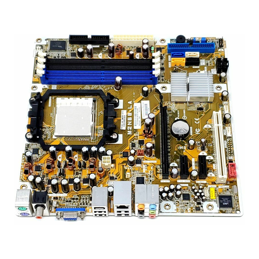
Super Asus SPDIF_OUT F8000 SPDIF_OUT 1394+USB ATX_CPU LAN+USB M2N68-LA RTL8201N AUDIO CHASSIS_FAN1 PCIE_X16 CR2032 3V Lithium Cell PCIE_X1_1 ALC888 CMOS Power ® BUZZER NVIDIA MCP61P PCIE_X1_2 F_LINE_IN BIOS F_AUDIO agere L-FW3227-100 F_1394 F_USB3 F_USB1 F_USB2 F_PANEL F_USB4 M2N68-LA (Narra 3) -
Page 6: Central Processing Unit (Cpu)
CPU! Installing the CPU To install a CPU: Locate the CPU socket on the motherboard. M2N68-LA M2N68-LA CPU Socket AM2 Unlock the socket by pressing the lever sideways, then lift it up to a 90º angle. Socket lever Make sure that the socket lever is lifted up to a 90º angle; otherwise, the CPU will not fit in completely. - Page 7 Carefully insert the CPU into the socket until it fits in place. Gold triangle Small triangle When the CPU is in place, push down the socket lever to secure the CPU. The lever clicks on the side tab to indicate that it is locked. Install a CPU heatsink and fan following the instructions that came with the heatsink package. M2N68-LA (Narra 3)
-
Page 8: System Memory
The motherboard comes with four Double Data Rate 2 (DDR2) Dual Inline Memory Modules (DIMM) sockets. A DDR2 module has the same physical dimensions as a DDR DIMM but has a 240-pin footprint compared to the 184-pin DDR DIMM. DDR2 DIMMs are notched differently to prevent installation on a DDR DIMM socket. The following figure illustrates the location of the DDR2 DIMM sockets: M2N68-LA M2N68-LA 240-pin DDR2 DIMM sockets Memory configurations You may install 256 MB, 512 MB, and 1 GB DDR2 SDRAM DIMMs into the DIMM sockets. • Always use identical (the same type and size) DDR2 DIMM pairs for dual channel mode. For optimum compatibility, we recommend that you obtain memory modules from the same vendor. -
Page 9: Installing A Dimm
DIMM into a socket to avoid damaging the DIMM. • The DDR2 DIMM sockets do not support DDR DIMMs. DO not install DDR DIMMs to the DDR2 DIMM sockets. Removing a DIMM To remove a DIMM: Simultaneously press the retaining clips outward to unlock the DIMM. Support the DIMM lightly with your fingers when pressing the retaining clips. The DIMM might DDR2 DIMM notch get damaged when it flips out with extra force. Remove the DIMM from the socket. M2N68-LA (Narra 3) -
Page 10: Expansion Slots
PCI Express specifications. The figure shows a network card installed on the PCI Express x1 slot. PCI slots The PCI slots support cards such as a LAN card, SCSI card, USB card, and other cards that comply with PCI specifications. The figure shows a LAN card installed on a PCI slot. M2N68-LA (Narra 3) -
Page 11: Jumpers
1. Turn OFF the computer and unplug the power cord. 2. Remove the onboard battery. 3. Move the jumper cap from pins 2-3 (Normal) to pins 1-2 (Clear CMOS). Keep the cap on pins 1-2 for about 5~10 seconds, then move the cap back to pins 2-3. 4. Reinstall the battery. 5. Plug the power cord and turn ON the computer. 6. Hold down the <F1> key during the boot process and enter BIOS setup to re-enter data. Except when clearing the RTC RAM, never remove the cap on CLRTC jumper default position. Removing the cap will cause system boot failure! M2N68-LA CLEAR CMOS Clear CMOS Normal (Default) M2N68-LA Clear RTC RAM M2N68-LA (Narra 3) - Page 12 Clear password (3-pin CLRPW) This jumper allows you to clear the password if you forgot your password. To erase the password: 1. Turn OFF the computer and unplug the power cord. 2. Move the jumper cap from pins 2-3 (Normal) to pins 1-2 (Clear Password). 3. Plug the power cord and turn ON the computer. 4. After the computer boots up, turn OFF the computer. 5. Move the jumper cap from pins 1-2 to pins 2-3. 6. Hold down the <F1> key during the boot process and enter BIOS setup to verify that the password has been cleared. M2N68-LA CLEAR P.W Clear Password Normal (Default) M2N68-LA Clear password setting M2N68-LA (Narra 3)
-
Page 13: Connectors
ORANGE Transmitting LAN port Side Speaker Out port (gray). This port connects to the side speakers in an 8-channel audio configuration. Rear Speaker Out port (black). This port connects to the rear speakers on a 4-channel, 6-channel, or 8-channel audio configuration. Center/Subwoofer port (yellow orange). This port connects the center/ subwoofer speakers. Line In port (light blue). This port connects the tape, CD, DVD player, or other audio sources. Line Out port (lime). This port connects a headphone or a speaker. In 4- channel, 6-channel, and 8-channel mode, the function of this port becomes Front Speaker Out. 10. Microphone port (pink). This port connects a microphone. M2N68-LA (Narra 3) - Page 14 Mic In Mic In Orange – – Center/Subwoofer Center/Subwoofer Black – Rear Speaker Out Rear Speaker Out Rear Speaker Out Gray – – – Side Speaker Out 11.. USB 2.0 ports. These four 4-pin Universal Serial Bus (USB) ports are available for connecting USB 2.0 devices. 12. VGA port. This 15-pin VGA port connects to a VGA monitor. 13. PS/2 keyboard port (purple). This port is for a PS/2 keyboard. M2N68-LA (Narra 3)
-
Page 15: Internal Connectors
Pin 5 on the connector is removed to prevent incorrect cable connection when using a FDD cable with a covered Pin 5. FLOPPY NOTE: Orient the red markings on the floppy ribbon cable to PIN 1. M2N68-LA PIN 1 M2N68-LA Floppy disk drive connector M2N68-LA (Narra 3) - Page 16 Pin 20 on the IDE connector is removed to match the covered hole on the Ultra DMA cable connector. This prevents incorrect insertion when you connect the IDE cable. • Use the 80-conductor IDE cable for Ultra DMA 100/66 IDE devices. If any device jumper is set as “Cable-Select,” make sure all other device jumpers have the same setting. PRIMARY_IDE NOTE: Orient the red markings (usually zigzag) on the IDE ribbon cable to PIN 1. M2N68-LA M2N68-LA IDE connector PIN 1 M2N68-LA (Narra 3)
- Page 17 Power OK -5 Volts Ground Ground +5 Volts Ground Ground Ground +5 Volts PSON# Ground Ground +3 Volts -12 Volts M2N68-LA ATX power connectors +3 Volts +3 Volts • Do not forget to connect the 4-pin ATX +12 V power plug; otherwise, the system will not boot up. • Make sure that your ATX 12V power supply can provide 8A on the +12V lead and at least 1A on the +5-volt standby lead (+5VSB). The minimum recommended wattage is 230 W, or 300W for a fully configured system. The system can become unstable and might experience difficulty powering up if the power supply is inadequate. • Use of a PSU with a higher power output is recommended when configuring a system with more power-consuming devices. The system may become unstable or may not boot up if the power is inadequate.
- Page 18 USB connectors (10-1 pin P24 F_USB1, 10-1 pin P150 F_USB2,. 5-1 pin P151 F_USB1, 5-1 pin P152 F_USB2) These connectors are for USB 2.0 ports. Connect the USB/GAME module cable to any of these connectors, then install the module to a slot opening at the back of the system chassis. These USB connectors comply with USB 2.0 specification that supports up to 480 Mbps connection speed. F_USB1 F_USB2 M2N68-LA M2N68-LA USB 2.0 connectors Never connect a 1394 cable to the USB connectors. Doing so will damage the motherboard! M2N68-LA (Narra 3)
-
Page 19: Cpu And Chassis Fan Connectors
CPU and Chassis fan connectors (3-pin CPU_FAN,. 3-pin CHASSIS_FAN1) The fan connectors support cooling fans of 350mA~740mA (8.88W max.) or a total of 1A~2.22A (26.64W max.) at +12V. Connect the fan cables to the fan connectors on the motherboard, making sure that the black wire of each cable matches the ground pin of the connector. Do not forget to connect the fan cables to the fan connectors. Insufficient air flow inside the system may damage the motherboard components. These are not jumpers! DO NOT place jumper caps on the fan connectors. CPU_FAN Rotation +12V M2N68-LA CHASSIS_FAN1 +12V Rotation M2N68-LA Fan connectors Front panel audio connector (10-1 pin F_AUDIO) This connector is for a chassis-mounted front panel audio I/O module that supports Azalia audio standard. M2N68-LA F_AUDIO PIN1 M2N68-LA Front audio connector M2N68-LA (Narra 3) - Page 20 Internal audio connector (4-pin F_LINE_IN) This connector allows you to receive stereo audio input from sound sources such as a CD-ROM, TV tuner, or MPEG card. M2N68-LA F_LINE_IN M2N68-LA Internal audio connector M2N68-LA (Narra 3)
-
Page 21: System Panel Connector
System panel connector (10-1 pin F_PANEL) This connector supports several chassis-mounted functions. PWR LED PWR BTN M2N68-LA F_PANEL HD LED RESET M2N68-LA System panel connector •.. System power LED (2-pin PLED) This 2-pin connector is for the system power LED. Connect the chassis power LED cable to this connector. The system power LED lights up when you turn on the system power, and blinks when the system is in sleep mode. •. Hard disk drive activity LED (2-pin HDLED) This 2-pin connector is for the HDD Activity LED. Connect the HDD Activity LED cable to this connector. The IDE LED lights up or flashes when data is read from or written to the HDD. - Page 22 M2N68-LA (Narra 3)
Need help?
Do you have a question about the M2N68-LA and is the answer not in the manual?
Questions and answers
Какие процессоры можно поставить на эту плату
The Asus M2N68-LA (Narra 3) motherboard supports the following processors:
- AMD Athlon™ 64
- AMD Athlon™ 64 X2
- AMD Sempron™ Rev F / Rev G (89W)
- AMD Phenom X4 9600 (95W)
- AMD Phenom X2 (65W and 89W)
It uses a Socket AM2 and also supports Socket AM2+ processors with a front-side bus (FSB) of up to 2000MT/sec.
This answer is automatically generated