TP-Link TL-SG2008 User Manual
8-port gigabit smart switch
Hide thumbs
Also See for TL-SG2008:
- Reference manual (169 pages) ,
- Quick installation manual (54 pages) ,
- Installation manual (2 pages)
Table of Contents
Advertisement
Quick Links
Advertisement
Table of Contents

Related Manuals for TP-Link TL-SG2008


Summary of Contents for TP-Link TL-SG2008
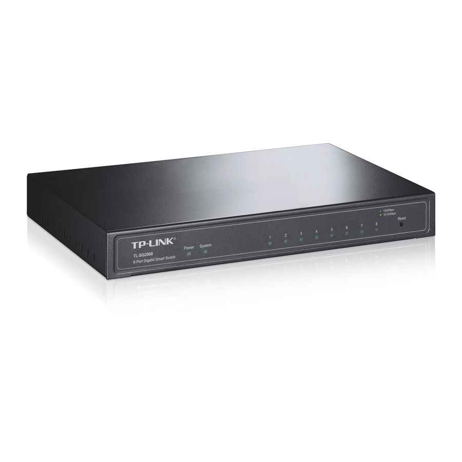
- Page 1 TL-SG2008 8-Port Gigabit Smart Switch REV1.0.0 1910010984...
-
Page 2: Fcc Statement
Specifications are subject to change without notice. is a registered trademark of TP-LINK TECHNOLOGIES CO., LTD. Other brands and product names are trademarks or registered trademarks of their respective holders. No part of the specifications may be reproduced in any form or by any means or used to make any derivative such as translation, transformation, or adaptation without permission from TP-LINK TECHNOLOGIES CO., LTD. -
Page 3: Safety Information
Safety Information When product has power button, the power button is one of the way to shut off the product; When there is no power button, the only way to completely shut off power is to disconnect the product or the power adapter from the power source. Don’t disassemble the product, or make repairs yourself. -
Page 4: Table Of Contents
CONTENTS Package Contents ..........................1 Chapter 1 About this Guide......................2 Intended Readers ......................2 Conventions........................2 Overview of This Guide ....................2 Chapter 2 Introduction ........................5 Overview of the Switch ....................5 Main Features.......................5 Appearance Description ....................5 2.3.1 Front Panel ......................5 2.3.2 Rear Panel ......................6 Chapter 3 Login to the Switch.......................7 Login..........................7 Configuration ........................7... - Page 5 5.1.1 Port Config .......................28 5.1.2 Port Mirror ......................29 5.1.3 Port Security ....................31 5.1.4 Port Isolation ....................32 5.1.5 Loopback Detection ..................33 LAG ..........................34 5.2.1 LAG Table ......................35 5.2.2 Static LAG ......................36 5.2.3 LACP Config ....................37 Traffic Monitor ......................39 5.3.1 Traffic Summary....................39 5.3.2 Traffic Statistics ....................40 MAC Address......................41...
- Page 6 8.1.1 Snooping Config ....................79 8.1.2 Port Config .......................80 8.1.3 VLAN Config ....................81 8.1.4 Multicast VLAN ....................82 Multicast IP .........................85 8.2.1 Multicast IP Table .....................85 8.2.2 Static Multicast IP.....................86 Multicast Filter......................87 8.3.1 IP-Range......................88 8.3.2 Port Filter ......................88 Packet Statistics......................90 Chapter 9 QoS..........................92 DiffServ ........................95 9.1.1 Port Priority ......................95...
- Page 7 10.3.2 Port Binding ....................113 10.3.3 VLAN Binding....................113 10.4 Application Example for ACL ..................114 Chapter 11 SNMP........................117 11.1 SNMP Config ......................119 11.1.1 Global Config ....................119 11.1.2 SNMP View ....................120 11.1.3 SNMP Group....................120 11.1.4 SNMP User ....................122 11.1.5 SNMP Community..................124 11.2...
-
Page 8: Package Contents
Package Contents The following items should be found in your box: One TL-SG2008 8-Port Gigabit Smart Switch One power adapter Four rubber cushions Quick Installation Guide Resource CD for TL-SG2008 switch, including: • This User Guide • Other Helpful Information Note: Make sure that the package contains the above items. -
Page 9: Chapter 1 About This Guide
Chapter 1 About this Guide This User Guide contains information for setup and management of TL-SG2008 8-Port Gigabit Smart Switch. Please read this guide carefully before operation. 1.1 Intended Readers This Guide is intended for network managers familiar with IT concepts and network terminologies. - Page 10 Chapter Introduction Chapter 4 System This module is used to configure system properties of the switch. Here mainly introduces: System Info: Configure the description, system time and network parameters of the switch. User Management: Configure the user name and password for users to log on to the Web management page with a certain access level.
- Page 11 Chapter Introduction Chapter 9 QoS This module is used to configure QoS function to provide different quality of service for various network applications and requirements. Here mainly introduces: DiffServ: Configure priorities, port priority, 802.1P priority and DSCP priority. Bandwidth Control: Configure rate limit feature to control the traffic rate on each port;...
-
Page 12: Chapter 2 Introduction
Link aggregation (LACP) increase aggregated bandwidth, optimizing the transport of business critical data. SNMP, RMON, WEB/Telnet Log-in bring abundant management policies. TL-SG2008 switch integrates multiple functions with excellent performance, and is friendly to manage, which can fully meet the need of the users demanding higher networking performance. -
Page 13: Rear Panel
Flashing Data is being transmitted or received. 2.3.2 Rear Panel The rear panel of TL-SG2008 features a power socket and eight ports. Its rear panel is shown as the following figure. Figure 2-2 Rear Panel of TL-SG2008 1000Mbps Ports: Designed to connect to the device with a bandwidth of 10Mbps, 100Mbps or 1000Mbps. -
Page 14: Chapter 3 Login To The Switch
Chapter 3 Login to the Switch 3.1 Login 1) To access the configuration utility, open a web-browser and type in the default address http://192.168.0.1 in the address field of the browser, then press the Enter key. Figure 3-1 Web-browser Tips: To log in to the switch, the IP address of your PC should be set in the same subnet addresses of the switch. - Page 15 Figure 3-3 Main Setup-Menu Note: Clicking Apply can only make the new configurations effective before the switch is rebooted. If you want to keep the configurations effective even the switch is rebooted, please click Save Config. You are suggested to click Save Config before cutting off the power or rebooting the switch to avoid losing the new configurations.
-
Page 16: Chapter 4 System
Chapter 4 System The System module is mainly for system configuration of the switch, including four submenus: System Info, User Management, System Tools and Access Security. 4.1 System Info The System Info, mainly for basic properties configuration, can be implemented on System Summary, Device Description, System Time, Daylight Saving Time and System IP pages. -
Page 17: Device Description
Figure 4-2 Port Information Port Info Port: Displays the port number of the switch. Type: Displays the type of the port. Rate: Displays the maximum transmission rate of the port. Status: Displays the connection status of the port. Click a port to display the bandwidth utilization on this port. The actual rate divided by theoretical maximum rate is the bandwidth utilization. -
Page 18: System Time
Figure 4-4 Device Description The following entries are displayed on this screen: Device Description Device Name: Enter the name of the switch. Device Location: Enter the location of the switch. System Contact: Enter your contact information. 4.1.3 System Time System Time is the time displayed while the switch is running. On this page you can configure the system time and the settings here will be used for other time-based functions. -
Page 19: Daylight Saving Time
Time Config Manual: When this option is selected, you can set the date and time manually. Get Time from NTP When this option is selected, you can configure the time zone Server: and the IP Address for the NTP Server. The switch will get UTC automatically if it has connected to an NTP Server. -
Page 20: System Ip
Predefined Mode: Select a predefined DST configuration. USA: Second Sunday in March, 02:00 ~ First Sunday in November, 02:00. Australia: First Sunday in October, 02:00 ~ First Sunday in April, 03:00. Europe: Last Sunday in March, 01:00 ~ Last Sunday in October, 01:00. -
Page 21: User Management
IP Config MAC Address: Displays MAC Address of the switch. IP Address Mode: Select the mode to obtain IP Address for the switch. Static IP: When this option is selected, you should enter IP Address, Subnet Mask and Default Gateway manually. DHCP: When this option is selected, the switch will obtain network parameters from the DHCP Server. -
Page 22: User Config
Figure 4-8 User Table 4.2.2 User Config On this page you can configure the access level of the user to log on to the Web management page. The switch provides two access levels: Guest and Admin. The guest only can view the settings without the right to configure the switch;... -
Page 23: System Tools
Confirm Password: Retype the password. Password Display Simple: Select a simple password display mode. Mode: Cipher: Select a cipher password display mode. User Table Select: Select the desired entry to delete the corresponding user information. It is multi-optional. The current user information can’t be deleted. -
Page 24: Config Backup
4.3.3 Firmware Upgrade The switch system can be upgraded via the Web management page. To upgrade the system is to get more functions and better performance. Go to http://www.tp-link.com to download the updated firmware. Choose the menu System→System Tools→Firmware Upgrade to load the following page. -
Page 25: System Reboot
Figure 4-12 Firmware Upgrade Note: Don’t interrupt the upgrade. Please select the proper software version matching with your hardware to upgrade. To avoid damage, please don't turn off the device while upgrading. After upgrading, the device will reboot automatically. You are suggested to backup the configuration before upgrading. 4.3.4 System Reboot On this page you can reboot the switch and return to the login page. -
Page 26: Access Security
Figure 4-14 System Reset Note: After the system is reset, the switch will be reset to the default and all the settings will be cleared. 4.4 Access Security Access Security provides different security measures for the remote login so as to enhance the configuration management security. -
Page 27: Ssl Config
Access Control Config Control Mode: Select the control mode for users to log on to the Web management page. Disable:Disable the access control function. IP-based: Select this option to limit the IP-range of the users for login. MAC-based: Select this option to limit the MAC Address of the users for login. - Page 28 default the switch has a certificate (self-signed certificate) and a corresponding private key. The Certificate/Key Download function enables the user to replace the default key pair. After SSL is effective, you can log on to the Web management page via https://192.168.0.1. For the first time you use HTTPS connection to log into the switch with the default certificate, you will be prompted that “The security certificate presented by this website was not issued by a trusted certificate authority”...
-
Page 29: Ssh Config
It may take more time for https connection than that for http connection, because https connection involves authentication, encryption and decryption etc. 4.4.3 SSH Config As stipulated by IFTF (Internet Engineering Task Force), SSH (Secure Shell) is a security protocol established on application and transport layers. - Page 30 Idle Timeout: Specify the idle timeout time. The system will automatically release the connection when the time is up. The default time is 120 seconds. Max Connect: Specify the maximum number of the connections to the SSH server. No new connection will be established when the number of the connections reaches the maximum number you set.
- Page 31 2. Click the Open button in the above figure to log on to the switch. Enter the login user name and password, and then you can continue to configure the switch. Application Example 2 for SSH: Network Requirements 1. Log on to the switch via key authentication using SSH and the SSH function is enabled on the switch.
- Page 32 Note: The key length is in the range of 256 to 3072 bits. During the key generation, randomly moving the mouse quickly can accelerate the key generation. 2. After the key is successfully generated, please save the public key and private key to the computer.
- Page 33 3. On the Web management page of the switch, download the public key file saved in the computer to the switch. Note: The key type should accord with the type of the key file. The SSH key downloading can not be interrupted. 4.
- Page 34 After successful authentication, please enter the login user name. If you log on to the switch without entering password, it indicates that the key has been successfully downloaded. Return to CONTENTS...
-
Page 35: Chapter 5 Switching
Chapter 5 Switching Switching module is used to configure the basic functions of the switch, including four submenus: Port, LAG, Traffic Monitor and MAC Address. 5.1 Port The Port function, allowing you to configure the basic features for the port, is implemented on the Port Config, Port Mirror, Port Security, Port Isolation and Loopback Detection pages. -
Page 36: Port Mirror
Duplex mode with the switch. When “Auto” is selected, the Speed and Duplex mode will be determined by auto-negotiation. For the SFP port, this switch does not support auto-negotiation. Flow Control: Allows you to Enable/Disable the Flow Control feature. When Flow Control is enabled, the switch can synchronize the speed with its peer to avoid the packet loss caused by congestion. - Page 37 Click Edit to display the following figure. Figure 5-3 Port Mirror Config The following entries are displayed on this screen: Mirror Group Number: Select the mirror group number you want to configure. Mirroring Port Mirroring Port: Select the mirroring port number. Mirrored Port Port Select: Click the Select button to quick-select the corresponding port based...
-
Page 38: Port Security
Note: The LAG member can not be selected as the mirrored port or mirroring port. A port can not be set as the mirrored port and the mirroring port simultaneously. The Port Mirror function can take effect span the multiple VLANs. 5.1.3 Port Security MAC Address Table maintains the mapping relationship between the port and the MAC address of the connected device, which is the base of the packet forwarding. -
Page 39: Port Isolation
Max Learned MAC: Specify the maximum number of MAC addresses that can be learned on the port. Learned Num: Displays the number of MAC addresses that have been learned on the port. Learn Mode: Select the Learn Mode for the port. •... -
Page 40: Loopback Detection
Port Isolation Config Port: Select the port number to set its forwardlist. Forward Portlist: Select the port that to be forwarded to. Port Isolation List Port: Display the port number. Forward Portlist: Display the forwardlist. 5.1.5 Loopback Detection With loopback detection feature enabled, the switch can detect loops using loopback detection packets. -
Page 41: Lag
Automatic Recovery Time after which the blocked port would automatically recover to Time : normal status. It can be set as integral times of detection interval. Web Refresh Status: Here you can enable or disable web automatic refresh. Web Refresh Interval: Set a web refresh interval between 3 and 100 seconds. -
Page 42: Lag Table
If the LAG is needed, you are suggested to configure the LAG function here before configuring the other functions for the member ports. Tips: Calculate the bandwidth for a LAG: If a LAG consists of the four ports in the speed of 1000Mbps Full Duplex, the whole bandwidth of the LAG is up to 8000Mbps (2000Mbps * 4) because the bandwidth of each member port is 2000Mbps counting the up-linked speed of 1000Mbps and the down-linked speed of 1000Mbps. -
Page 43: Static Lag
Group Number: Displays the LAG number here. Description: Displays the description of LAG. Member: Displays the LAG member. Operation: Allows you to view or modify the information for each LAG. • Edit: Click to modify the settings of the LAG. •... -
Page 44: Lacp Config
LAG Config Group Number: Select a Group Number for the LAG. Description: Displays the description of the LAG. Member Port Member Port: Select the port as the LAG member. Clearing all the ports of the LAG will delete this LAG. Tips: The LAG can be deleted by clearing its all member ports. - Page 45 Figure 5-10 LACP Config The following entries are displayed on this screen: Global Config System Priority: Specify the system priority for the switch. The system priority and MAC address constitute the system identification (ID). A lower system priority value indicates a higher system priority. When exchanging information between systems, the system with higher priority determines which link aggregation a link belongs to, and the system with lower priority adds the proper links to the link aggregation...
-
Page 46: Traffic Monitor
LAG: Displays the LAG number which the port belongs to. 5.3 Traffic Monitor The Traffic Monitor function, monitoring the traffic of each port, is implemented on the Traffic Summary and Traffic Statistics pages. 5.3.1 Traffic Summary Traffic Summary screen displays the traffic information of each port, which facilitates you to monitor the traffic and analyze the network abnormity. -
Page 47: Traffic Statistics
Octets Rx: Displays the number of octets received on the port. The error octets are counted in. Octets Tx: Displays the number of octets transmitted on the port. Statistics: Click the Statistics button to view the detailed traffic statistics of the port. -
Page 48: Mac Address
Broadcast: Displays the number of good broadcast packets received or transmitted on the port. The error frames are not counted in. Multicast: Displays the number of good multicast packets received or transmitted on the port. The error frames are not counted in. Unicast: Displays the number of good unicast packets received or transmitted on the port. -
Page 49: Address Table
Being kept after Relationship between the reboot bound MAC address and Configuration Type Aging out the port (if the configuration is saved) Dynamic Automatically The bound MAC address can be learned by the other Address Table learning ports in the same VLAN. Filtering Manually Address Table... -
Page 50: Static Address
Filtering: This option allows the address table to display the filtering address entries only. Address Table MAC Address: Displays the MAC address learned by the switch. VLAN ID: Displays the corresponding VLAN ID of the MAC address. Port: Displays the corresponding Port number of the MAC address. Type: Displays the Type of the MAC address. -
Page 51: Dynamic Address
Search Option Search Option: Select a Search Option from the pull-down list and click the Search button to find your desired entry in the Static Address Table. • MAC: Enter the MAC address of your desired entry. • VLAN ID: Enter the VLAN ID number of your desired entry. •... - Page 52 Figure 5-15 Dynamic Address The following entries are displayed on this screen: Aging Config Auto Aging: Allows you to Enable/Disable the Auto Aging feature. Aging Time: Enter the Aging Time for the dynamic address. Search Option Search Option: Select a Search Option from the pull-down list and click the Search button to find your desired entry in the Dynamic Address Table.
-
Page 53: Filtering Address
Tips: Setting aging time properly helps implement effective MAC address aging. The aging time that is too long or too short results decreases the performance of the switch. If the aging time is too long, excessive invalid MAC address entries maintained by the switch may fill up the MAC address table. This prevents the MAC address table from updating with network changes in time. -
Page 54: Dhcp Filtering
Filtering Address Table Select: Select the entry to delete the corresponding filtering address. It is multi-optional. MAC Address: Displays the filtering MAC Address. VLAN ID: Displays the corresponding VLAN ID. Port: Here the symbol “__” indicates no specified port. Type: Displays the Type of the MAC address. - Page 55 Figure 5-17 Network diagram of DHCP For different DHCP clients, DHCP server provides three IP address assigning methods: Manually assign the IP address: Allows the administrator to bind the static IP address to a specific client (e.g.: WWW Server) via the DHCP server. Automatically assign the IP address: DHCP server assigns the IP address without an expiry time limitation to the clients.
- Page 56 packet and broadcast the DHCP-REQUEST packet which includes the assigned IP address of the DHCP-OFFER packet. (4) DHCP-ACK Stage: Since the DHCP-REQUEST packet is broadcasted, all DHCP servers on the network segment can receive it. However, only the requested server processes the request.
- Page 57 Figure 5-20 DHCP Filtering The following entries are displayed on this screen: DHCP Filtering Enable/Disable the DHCP Filtering function globally. DHCP Filtering: Trusted Port Here you can select the desired port(s) to be Trusted Port(s). Only the Trusted Port(s) can receive DHCP packets from DHCP Servers.
-
Page 58: Chapter 6 Vlan
Chapter 6 VLAN The traditional Ethernet is a data network communication technology based on CSMA/CD (Carrier Sense Multiple Access/Collision Detect) via shared communication medium. Through the traditional Ethernet, the overfull hosts in LAN will result in serious collision, flooding broadcasts, poor performance or even breakdown of the Internet. -
Page 59: Link Types Of Ports
6.1 802.1Q VLAN VLAN tags in the packets are necessary for the switch to identify packets of different VLANs. The switch works at the data link layer in OSI model and it can identify the data link layer encapsulation of the packet only, so you can add the VLAN tag field into the data link layer encapsulation for identification. -
Page 60: Vlan Config
ingress port belongs to, this packet will be dropped. When the VLAN-tagged packets are forwarded by the Tagged port, its VLAN tag will not be changed. PVID PVID (Port VLAN ID) is the default VID of the port. When the switch receives an un-VLAN-tagged packet, it will add a VLAN tag to the packet according to the PVID of its received port and forward the packets. - Page 61 Figure 6-3 VLAN Table To ensure the normal communication of the factory switch, the default VLAN of all ports is set to VLAN1. VLAN1 cannot be modified or deleted. The following entries are displayed on this screen: VLAN Create Enter the VLAN ID you want to create. It ranges from 2 to 4094. VLAN ID:...
-
Page 62: Application Example For 802.1Q Vlan
Untagged: The port will be an untagged member of the specific VLAN if you select it. Tagged: The port will be an tagged member of the specific VLAN if you select it. NotMember: The port will not be a member of the specific VLAN if you select PVID: Here you can change the PVID of the specific port. - Page 63 Configuration Procedure Configure Switch A Step Operation Description Configure Required. On VLAN→802.1Q VLAN→VLAN Config page, configure the link type of Port 2, Port 3 and Port 4 as Untagged, Tagged and Link Type of the Untagged respectively ports Create VLAN10 Required.
-
Page 64: Chapter 7 Spanning Tree
Chapter 7 Spanning Tree STP (Spanning Tree Protocol), subject to IEEE 802.1D standard, is to disbranch a ring network in the Data Link layer in a local network. Devices running STP discover loops in the network and block ports by exchanging information, in that way, a ring network can be disbranched to form a tree-topological ring-free network to prevent packets from being duplicated and forwarded endlessly in the network. - Page 65 Figure 7-1 Basic STP diagram STP Timers Hello Time: Hello Time ranges from 1 to 10 seconds. It specifies the interval to send BPDU packets. It is used to test the links. Max. Age: Max. Age ranges from 6 to 40 seconds. It specifies the maximum time the switch can wait without receiving a BPDU before attempting to reconfigure.
- Page 66 Comparing BPDUs Each switch sends out configuration BPDUs and receives a configuration BPDU on one of its ports from another switch. The following table shows the comparing operations. Step Operation If the priority of the BPDU received on the port is lower than that of the BPDU if of the port itself, the switch discards the BPDU and does not change the BPDU of the port.
- Page 67 RSTP (Rapid Spanning Tree Protocol), evolved from the 802.1D STP standard, enable Ethernet ports to transit their states rapidly. The premises for the port in the RSTP to transit its state rapidly are as follows. The condition for the root port to transit its port state rapidly: The old root port of the switch stops forwarding data and the designated port of the upstream switch begins to forward data.
- Page 68 Figure 7-2 Basic MSTP diagram MSTP MSTP divides a network into several MST regions. The CST is generated between these MST regions, and multiple spanning trees can be generated in each MST region. Each spanning tree is called an instance. As well as STP, MSTP uses BPDUs to generate spanning tree. The only difference is that the BPDU for MSTP carries the MSTP configuration information on the switches.
-
Page 69: Stp Config
Figure 7-3 Port roles The Spanning Tree module is mainly for spanning tree configuration of the switch, including four submenus: STP Config, Port Config, MSTP Instance and STP Security. 7.1 STP Config The STP Config function, for global configuration of spanning trees on the switch, can be implemented on STP Config and STP Summary pages. - Page 70 The following entries are displayed on this screen: Global Config STP: Select Enable/Disable STP function globally on the switch. Version: Select the desired STP version on the switch. STP: Spanning Tree Protocol. RSTP: Rapid Spanning Tree Protocol. MSTP: Multiple Spanning Tree Protocol. Parameters Config CIST Priority: Enter a value from 0 to 61440 to specify the priority of the switch...
-
Page 71: Stp Summary
7.1.2 STP Summary On this page you can view the related parameters for Spanning Tree function. Choose the menu Spanning Tree→STP Config→STP Summary to load the following page. Figure 7-5 STP Summary 7.2 Port Config On this page you can configure the parameters of the ports for CIST Choose the menu Spanning Tree→Port Config to load the following page. - Page 72 The following entries are displayed on this screen: Port Config Port Select: Click the Select button to quick-select the corresponding port based on the port number you entered. Select: Select the desired port for STP configuration. It is multi-optional. Port: Displays the port number of the switch.
-
Page 73: Mstp Instance
Disconnected: In this status the port is not participating in the STP. LAG: Displays the LAG number which the port belongs to. Note: Configure the ports connected directly to terminals as edge ports and enable the BPDU protection function as well. This not only enables these ports to transit to forwarding state rapidly but also secures your network. - Page 74 Figure 7-8 Instance Config The following entries are displayed on this screen: Instance Table Instance ID Select: Click the Select button to quick-select the corresponding Instance ID based on the ID number you entered. Select: Select the desired Instance ID for configuration. It is multi-optional. Instance: Displays Instance ID of the switch.
-
Page 75: Instance Port Config
Instance ID: Enter the corresponding instance ID. 7.3.3 Instance Port Config A port can play different roles in different spanning tree instance. On this page you can configure the parameters of the ports in different instance IDs as well as view status of the ports in the specified instance. -
Page 76: Stp Security
Note: The port status of one port in different spanning tree instances can be different. Global configuration Procedure for Spanning Tree function: Step Operation Description Make clear roles the switches Preparation. play spanning tree instances: root bridge designated bridge Globally configure MSTP Required. - Page 77 Root Protect A CIST and its secondary root bridges are usually located in the high-bandwidth core region. Wrong configuration or malicious attacks may result in configuration BPDU packets with higher priorities being received by the legal root bridge, which causes the current legal root bridge to lose its position and network topology jitter to occur.
-
Page 78: Tc Protect
Figure 7-10 Port Protect The following entries are displayed on this screen: Port Protect Port Select: Click the Select button to quick-select the corresponding port based on the port number you entered. Select: Select the desired port for port protect configuration. It is multi-optional. -
Page 79: Application Example For Stp Function
Figure 7-11 TC Protect The following entries are displayed on this screen: TC Protect TC Threshold: Enter a number from 1 to 100. It is the maximum number of the TC-BPDUs received by the switch in a TC Protect Cycle. The default value is 20. - Page 80 On Spanning Tree→STP Config→Port Config page, enable MSTP function for the port. Configure the region name and Spanning Tree→MSTP Instance→Region the revision of MST region Config page, configure the region as TP-LINK and keep the default revision setting. Configure VLAN-to-Instance Spanning Tree→MSTP Instance→Instance...
- Page 81 MSTP function for the port. Configure the region name and Spanning Tree→MSTP Instance→Region the revision of MST region Config page, configure the region as TP-LINK and keep the default revision setting. Configure VLAN-to-Instance On Spanning Tree→MSTP Instance→Instance mapping table of the MST region Config page, configure VLAN-to-Instance mapping table.
- Page 82 The topology diagram of the two instances after the topology is stable For Instance 1 (VLAN101, 103 and 105), the red paths in the following figure are connected links; the gray paths are the blocked links. For Instance 2 (VLAN102, 104 and 106), the blue paths in the following figure are connected links;...
-
Page 83: Chapter 8 Multicast
Chapter 8 Multicast Multicast Overview In the network, packets are sent in three modes: unicast, broadcast and multicast. In unicast, the source server sends separate copy information to each receiver. When a large number of users require this information, the server must send many pieces of information with the same content to the users. - Page 84 Multicast Address 1. Multicast IP Address: As specified by IANA (Internet Assigned Numbers Authority), Class D IP addresses are used as destination addresses of multicast packets. The multicast IP addresses range from 224.0.0.0~239.255.255.255. The following table displays the range and description of several special multicast IP addresses.
-
Page 85: Igmp Snooping
should be a group port list, so the switch will duplicate this multicast data and deliver each port one copy. The general format of the multicast address table is described as Figure 8-3 below. VLAN ID Multicast IP Port Figure 8-3 Multicast Address Table IGMP Snooping In the network, the hosts apply to the near router for joining (leaving) a multicast group by sending IGMP (Internet Group Management Protocol) messages. -
Page 86: Snooping Config
in the VLAN as well as analyze the message to get the address of the multicast group the host applies for joining. The receiving port will be processed: if the receiving port is a new member port, it will be added to the multicast address table with its member port time specified; if the receiving port is already a member port, its member port time will be directly reset. -
Page 87: Port Config
Figure 8-4 Basic Config The following entries are displayed on this screen: Global Config IGMP Snooping: Select Enable/Disable IGMP Snooping function globally on the switch. Unknown Multicast: Select the operation for the switch to process unknown multicast, Forward or Discard. IGMP Snooping Status Description: Displays IGMP Snooping status. -
Page 88: Vlan Config
The following entries are displayed on this screen: Port Config Port Select: Click the Select button to quick-select the corresponding port based on the port number you entered. Select: Select the desired port for IGMP Snooping feature configuration. It is multi-optional. Port: Displays the port of the switch. -
Page 89: Multicast Vlan
VLAN Config VLAN ID: Enter the VLAN ID to enable IGMP Snooping for the desired VLAN. Router Port Time: Specify the aging time of the router port. Within this time, if the switch doesn’t receive IGMP query message from the router port, it will consider this port is not a router port any more. - Page 90 VLAN owning a receiver one copy. This mode wastes a lot of bandwidth. The problem above can be solved by configuring a multicast VLAN. By adding switch ports to the multicast VLAN and enabling IGMP Snooping, you can make users in different VLANs share the same multicast VLAN.
- Page 91 The Multicast VLAN won't take effect unless you first complete the configuration for the corresponding VLAN owning the port on the 802.1Q VLAN page. Configure the link type of the router port in the multicast VLAN as Tagged otherwise all the member ports in the multicast VLAN can not receive multicast streams.
-
Page 92: Multicast Ip
Network Diagram Configuration Procedure Step Operation Description Create VLANs Create three VLANs with the VLAN ID 3, 4 and 5 respectively, and specify the description of VLAN3 as Multicast VLAN on VLAN→802.1Q VLAN page. Configure ports On VLAN→802.1Q VLAN function pages. For port 3, configure its link type as Tagged, and add it to VLAN3, VLAN4 and VLAN5. -
Page 93: Static Multicast Ip
Choose the menu Multicast→Multicast IP→Multicast IP Table to load the following page. Figure 8-8 Multicast IP Table The following entries are displayed on this screen: Search Option Multicast IP: Enter the multicast IP address the desired entry must carry. VLAN ID: Enter the VLAN ID the desired entry must carry. -
Page 94: Multicast Filter
Figure 8-9 Static Multicast IP Table The following entries are displayed on this screen: Create Static Multicast Multicast IP: Enter static multicast IP address. VLAN ID: Enter the VLAN ID of the multicast IP. Forward Port: Enter the forward port of the multicast group. Search Option Search Option: Select the rules for displaying multicast IP table to find the desired... -
Page 95: Ip-Range
port. If the port can be added to the multicast group, it will be added to the multicast address table; if the port can not be added to the multicast group, the switch will drop the IGMP report message. In that way, the multicast streams will not be transmitted to this port, which allows you to control hosts joining the multicast group. - Page 96 Choose the menu Multicast→Multicast Filter→Port Filter to load the following page. Figure 8-11 Port Filter The following entries are displayed on this screen: Port Filter Config Port Select: Click the Select button to quick-select the corresponding port based on the port number you entered. Select: Select the desired port for multicast filtering.
-
Page 97: Packet Statistics
Configuration Procedure: Step Operation Description Configure IP-Range Required. Configure IP-Range filtered Multicast→Multicast Filter→IP-Range page. Configure multicast filter Optional. Configure multicast filter rules for ports on rules for ports Multicast→Multicast Filter→Port Filter page. 8.4 Packet Statistics On this page you can view the multicast data traffic on each port of the switch, which facilitates you to monitor the IGMP messages in the network. - Page 98 Report Packet (V1): Displays the number of IGMPv1 report packets the port received. Report Packet (V2): Displays the number of IGMPv2 report packets the port received. Report Packet (V3): Displays the number of IGMPv3 report packets the port received. Leave Packet: Displays the number of leave packets the port received.
-
Page 99: Chapter 9 Qos
Chapter 9 QoS QoS (Quality of Service) functions to provide different quality of service for various network applications and requirements and optimize the bandwidth resource distribution so as to provide a network service experience of a better quality. This switch classifies the ingress packets, maps the packets to different priority queues and then forwards the packets according to specified scheduling algorithms to implement QoS function. - Page 100 2. 802.1P Priority Figure 9-2 802.1Q frame As shown in the figure above, each 802.1Q Tag has a Pri field, comprising 3 bits. The 3-bit priority field is 802.1p priority in the range of 0 to 7. 802.1P priority determines the priority of the packets based on the Pri value.
- Page 101 Figure 9-4 SP-Mode WRR-Mode: Weight Round Robin Mode. In this mode, packets in all the queues are sent in order based on the weight value for each queue and every queue can be assured of a certain service time. The weight value indicates the occupied proportion of the resource. WRR queue overcomes the disadvantage of SP queue that the packets in the queues with lower priority can not get service for a long time.
-
Page 102: Diffserv
The QoS module is mainly for traffic control and priority configuration, including two submenus: DiffServ and Bandwidth Control. 9.1 DiffServ This switch classifies the ingress packets, maps the packets to different priority queues and then forwards the packets according to specified scheduling algorithms to implement QoS function. This switch implements three priority modes based on port, on 802.1P and on DSCP, and supports four queue scheduling algorithms. -
Page 103: P/Cos Mapping
Configuration Procedure: Step Operation Description Select the port priority Required. On QoS→DiffServ→Port Priority page, configure the port priority. Select a schedule mode Required. On QoS→DiffServ→Schedule Mode page, select a schedule mode. 9.1.2 802.1P/CoS Mapping On this page you can configure 802.1P priority. 802.1P gives the Pri field in 802.1Q tag a recommended definition. -
Page 104: Dscp Priority
Configuration Procedure: Step Operation Description Log on to the 802.1P/CoS Mapping page Enable 802.1P priority Required. By default, the 802.1P priority function is function disabled. Map the 802.1P priority tag to Required. Select 802.1P priority the priority level corresponding priority level. Select a schedule mode Required. -
Page 105: Schedule Mode
Priority Level DSCP: Indicates the priority determined by the DS region of IP datagram. It ranges from 0 to 63. Priority Level: Indicates the priority level the packets with tag are mapped to. The priority levels are labeled as TC0, TC1, TC2 and TC3. Note: To complete QoS function configuration, you have to go to the Schedule Mode page to select a schedule mode after the configuration is finished on this page. -
Page 106: Bandwidth Control
SP+WRR-Mode: Strict-Priority + Weight Round Robin Mode. In this mode, this switch provides two scheduling groups, SP group and WRR group. Queues in SP group and WRR group are scheduled strictly based on strict-priority mode while the queues inside WRR group follow the WRR mode. In SP+WRR mode, TC3 is in the SP group;... -
Page 107: Storm Control
Select: Select the desired port for Rate configuration. It is multi-optional. Port: Displays the port number of the switch. Ingress Rate (bps): Configure the bandwidth for receiving packets on the port. You can select a rate from the dropdown list or select "Manual" to set Ingress rate, the system will automatically select integral multiple of 64Kbps that closest to the rate you entered as the real Ingress rate. -
Page 108: Voice Vlan
The following entries are displayed on this screen: Storm Control Config Port Select: Click the Select button to quick-select the corresponding port based on the port number you entered. Select: Select the desired port for Storm Control configuration. It is multi-optional. - Page 109 Number OUI Address Vendor 00-03-6b-00-00-00 Cisco phone 00-04-0d-00-00-00 Avaya phone 00-60-b9-00-00-00 Philips/NEC phone 00-d0-1e-00-00-00 Pingtel phone 00-e0-75-00-00-00 Polycom phone 00-e0-bb-00-00-00 3com phone Table 9-1 OUI addresses on the switch Port Voice VLAN Mode A voice VLAN can operate in two modes: automatic mode and manual mode. Automatic Mode: In this mode, the switch automatically adds a port which receives voice packets to voice VLAN and determines the priority of the packets through learning the source MAC of the UNTAG packets sent from IP phone when it is powered on.
-
Page 110: Global Config
Security Mode of Voice VLAN When voice VLAN is enabled for a port, you can configure its security mode to filter data stream. If security mode is enabled, the port just forwards voice packets, and discards other packets whose source MAC addresses do not match OUI addresses. If security mode is not enabled, the port forwards all the packets. -
Page 111: Port Config
VLAN ID: Enter the VLAN ID of the voice VLAN. Aging Time: Specifies the living time of the member port in auto mode after the OUI address is aging out. Priority: Select the priority of the port when sending voice data. 9.3.2 Port Config Before the voice VLAN function is enabled, the parameters of the ports in the voice VLAN should be configured on this page. -
Page 112: Oui Config
Security Mode: Configure the security mode for forwarding packets. Disable: All packets are forwarded. Enable: Only voice data are forwarded. Member State: Displays the state of the port in the current voice VLAN. LAG: Displays the LAG number which the port belongs to. 9.3.3 OUI Config The switch supports OUI creation and adds the MAC address of the special voice device to the OUI table of the switch. - Page 113 Configuration Procedure of Voice VLAN: Step Operation Description Configure the link type of Required. On VLAN→802.1Q VLAN→VLAN Config the port page, configure the link type of ports of the voice device. Create VLAN Required. On VLAN→802.1Q VLAN→VLAN Config page, click the Create button to create a VLAN. Add OUI address Optional.
-
Page 114: Chapter 10 Acl
Chapter 10 ACL 10.1 ACL Config An ACL may contain a number of rules, and each rule specifies a different package range. Packets are matched in match order. Once a rule is matched, the switch processes the matched packets taking the operation specified in the rule without considering the other rules, which can enhance the performance of the switch. -
Page 115: Mac Acl
Figure 10-2 ACL Create The following entries are displayed on this screen: Create ACL ACL ID: Enter ACL ID of the ACL you want to create. Rule Order: User Config order is set to be match order in this ACL. 10.1.3 MAC ACL MAC ACLs analyze and process packets based on a series of match conditions, which can be the source MAC addresses and destination MAC addresses carried in the packets. -
Page 116: Standard-Ip Acl
MASK: Enter MAC address mask. If it is set to 1, it must strictly match the address. 10.1.4 Standard-IP ACL Standard-IP ACLs analyze and process data packets based on a series of match conditions, which can be the source IP addresses and destination IP addresses carried in the packets. Choose the menu ACL→ACL Config→Standard-IP ACL to load the following page. -
Page 117: Policy Config
Figure 10-5 Create Extend-IP Rule The following entries are displayed on this screen: Create Extend-IP ACL ACL ID: Select the desired Extend-IP ACL for configuration. Rule ID: Enter the rule ID. Operation: Select the operation for the switch to process packets which match the rules. -
Page 118: Policy Create
Choose the menu ACL→Policy Config→Policy Summary to load the following page. Figure 10-6 Policy Summary The following entries are displayed on this screen: Search Option Select Policy: Select name of the desired policy for view. If you want to delete the desired policy, please click the Delete button. -
Page 119: Policy Binding
Figure 10-8 Action Create The following entries are displayed on this screen: Create Action Select Policy: Select the name of the policy. Select ACL: Select the ACL for configuration in the policy. 10.3 Policy Binding Policy Binding function can have the policy take its effect on a specific port/VLAN. The policy will take effect only when it is bound to a port/VLAN. -
Page 120: Port Binding
Interface: Displays the port number or VLAN ID bound to the policy. Direction: Displays the binding direction. 10.3.2 Port Binding On this page you can bind a policy to a port. Choose the menu ACL→Policy Binding→Port Binding to load the following page. Figure 10-10 Bind the policy to the port The following entries are displayed on this screen: Port-Bind Config... -
Page 121: Application Example For Acl
The following entries are displayed on this screen: VLAN-Bind Config Policy Name: Select the name of the policy you want to bind. VLAN ID: Enter the ID of the VLAN you want to bind. VLAN-Bind Table Index: Displays the index of the binding policy. Policy Name: Displays the name of the binding policy. - Page 122 Network Diagram Configuration Procedure Step Operation Description Configure On ACL→ACL Config→ACL Create page, create ACL 11. requirement 1 On ACL→ACL Config→MAC ACL page, select ACL 11, create Rule 1, configure the operation as Permit, configure the S-MAC as 00-64-A5-5D-12-C3 and mask as FF-FF-FF-FF-FF-FF. On ACL→Policy Config→Policy Create page, create a policy named manager.
- Page 123 Step Operation Description Configure On ACL→ACL Config→ACL Create page, create ACL 101. requirement On ACL→ACL Config→Standard-IP ACL page, select ACL 101, and 4 create Rule 4, configure operation as Deny, configure S-IP as 10.10.50.0 and mask as 255.255.255.0, configure D-IP as 10.10.70.0 and mask as 255.255.255.0.
-
Page 124: Chapter 11 Snmp
Chapter 11 SNMP SNMP Overview SNMP (Simple Network Management Protocol) has gained the most extensive application on the UDP/IP networks. SNMP provides a management frame to monitor and maintain the network devices. It is used for automatically managing the various network devices no matter the physical differences of the devices. - Page 125 SNMP v1: SNMP v1 adopts Community Name authentication. The community name is used to define the relation between SNMP Management Station and SNMP Agent. The SNMP packets failing to pass community name authentication are discarded. The community name can limit access to SNMP Agent from SNMP NMS, functioning as a password.
-
Page 126: Snmp Config
management station. The specified User Name and the Auth/Privacy Password are used for SNMP Management Station to access the SNMP Agent, functioning as the password. SNMP module is used to configure the SNMP function of the switch, including three submenus: SNMP Config, Notification and RMON. -
Page 127: Snmp View
11.1.2 SNMP View The OID (Object Identifier) of the SNMP packets is used to describe the managed objects of the switch, and the MIB (Management Information Base) is the set of the OIDs. The SNMP View is created for the SNMP management station to manage MIB objects. Choose the menu SNMP→SNMP Config→SNMP View to load the following page. - Page 128 Figure 11-5 SNMP Group The following entries are displayed on this screen: Group Config Group Name: Enter the SNMP Group name. The Group Name, Security Model and Security Level compose the identifier of the SNMP Group. The Groups with these three items the same are considered to be the same.
-
Page 129: Snmp User
Notify View: Select the View to be the Notify View. The management station can receive trap messages of the assigned SNMP view generated by the switch's SNMP agent. Group Table Select: Select the desired entry to delete the corresponding group. It is multi-optional. - Page 130 User Config User Name: Enter the User Name here. User Type: Select the type for the User. • Local User: Indicates that the user is connected to a local SNMP engine. • Remote User: Indicates that the user is connected to a remote SNMP engine.
-
Page 131: Snmp Community
11.1.5 SNMP Community SNMP v1 and SNMP v2c adopt community name authentication. The community name can limit access to the SNMP agent from SNMP network management station, functioning as a password. If SNMP v1 or SNMP v2c is employed, you can directly configure the SNMP Community on this page without configuring SNMP Group and User. -
Page 132: Configuration Procedure
Configuration Procedure: If SNMPv3 is employed, please take the following steps: Step Operation Description Enable SNMP function globally. Required. On the SNMP→SNMP Config→Global Config page, enable SNMP function globally. Create SNMP View. Required. On the SNMP→SNMP Config→SNMP View page, create SNMP View of the management agent. -
Page 133: Notification
11.2 Notification With the Notification function enabled, the switch can initiatively report to the management station about the important events that occur on the Views (e.g., the managed device is rebooted), which allows the management station to monitor and process the events in time. The notification information includes the following two types: Trap :... -
Page 134: Rmon
Type: Select the type for the notifications. • Trap: Indicates traps are sent. • Inform: Indicates informs are sent. The Inform type has a higher security than the Trap type. Retry: Specify the amount of times the switch resends an inform request. -
Page 135: History Control
RMON Group Function History Group After a history group is configured, the switch collects and records network statistics information periodically, based on which the management station can monitor network effectively. Event Group Event Group is used to define RMON events. Alarms occur when an event is detected. -
Page 136: Event Config
11.3.2 Event Config On this page, you can configure the RMON events. Choose the menu SNMP→RMON→Event Config to load the following page. Figure 11-10 Event Config The following entries are displayed on this screen: Event Table Select: Select the desired entry for configuration. Index: Displays the index number of the entry. - Page 137 Figure 11-11 Alarm Config The following entries are displayed on this screen: Alarm Table Select: Select the desired entry for configuration. Index: Displays the index number of the entry. Variable: Select the alarm variables from the pull-down list. Port: Select the port on which the Alarm entry acts. Sample Type: Specify the sampling method for the selected variable and comparing the value against the thresholds.
- Page 138 Owner: Enter the name of the device or user that defined the entry. Status: Select Enable/Disable the corresponding alarm entry. Note: When alarm variables exceed the Threshold on the same direction continuously for several times, an alarm event will only be generated on the first time, that is, the Rising Alarm and Falling Alarm are triggered alternately for that the alarm following to Rising Alarm is certainly a Falling Alarm and vice versa.
-
Page 139: Chapter 12 Maintenance
Chapter 12 Maintenance Maintenance module, assembling the commonly used system tools to manage the switch, provides the convenient method to locate and solve the network problem. (1) System Monitor: Monitor the utilization status of the memory and the CPU of switch. (2)... -
Page 140: Memory Monitor
Click the Monitor button to enable the switch to monitor and display its CPU utilization rate every four seconds. 12.1.2 Memory Monitor Choose the menu Maintenance→System Monitor→Memory Monitor to load the following page. Figure 12-2 Memory Monitor Click the Monitor button to enable the switch to monitor and display its Memory utilization rate every four seconds. -
Page 141: Log Table
Level Description Severity debugging Debug-level messages Table 12-1 Log Level The Log function is implemented on the Log Table, Local Log, Remote Log and Backup Log pages. 12.2.1 Log Table The switch supports logs output to two directions, namely, log buffer and log file. The information in log buffer will be lost after the switch is rebooted or powered off whereas the information in log file will be kept effective even the switch is rebooted or powered off. -
Page 142: Local Log
Severity: Displays the severity level of the log information. You can select a severity level to display the log information whose severity level value is the same or smaller. Content: Displays the content of the log information. Note: The logs are classified into eight levels based on severity. The higher the information severity is, the lower the corresponding level is. -
Page 143: Remote Log
12.2.3 Remote Log Remote log feature enables the switch to send system logs to the Log Server. Log Server is to centralize the system logs from various devices for the administrator to monitor and manage the whole network. Choose the menu Maintenance→Log→Remote Log to load the following page. Figure 12-5 Log Host The following entries are displayed on this screen: Log Host... -
Page 144: Device Diagnostics
Figure 12-6 Backup Log The following entry is displayed on this screen: Backup Log Backup Log: Click the Backup Log button to save the log as a file to your computer. Note: It will take a few minutes to backup the log file. Please wait without any operation. 12.3 Device Diagnostics This switch provides Cable Test and Loopback functions for device diagnostics. -
Page 145: Loopback
Length: If the connection status is normal, here displays the length range of the cable. Error: If the connection status is close, open or impedance, here displays the error length of the cable. Note: The interval between two cable tests for one port must be more than 3 seconds. The result is more reasonable when the cable pair is in the open status. -
Page 146: Ping
12.4.1 Ping Ping test function, testing the connectivity between the switch and one node of the network, facilitates you to test the network connectivity and reachability of the host so as to locate the network malfunctions. Choose the menu Maintenance→Network Diagnostics→Ping to load the following page. Figure 12-9 Ping The following entries are displayed on this screen: Ping Config... - Page 147 Figure 12-10 Tracert The following entries are displayed on this screen: Tracert Config Destination IP: Enter the IP address of the destination device. Max Hop: Specify the maximum number of the route hops the test data can pass through. Return to CONTENTS...
-
Page 148: Appendix A: Specifications
Appendix A: Specifications IEEE802.3 10Base-T Ethernet IEEE802.3u 100Base-TX/100Base-FX Fast Ethernet IEEE802.3ab 1000Base-T Gigabit Ethernet IEEE802.3ad Dynamic link aggregation IEEE802.3x Flow Control Standards IEEE802.1p QoS IEEE802.1q VLAN IEEE802.1d Spanning Tree IEEE802.1s Multiple Spanning Tree IEEE802.1w Rapid Spanning Tree Protocol Ethernet: 10Mbps HD,20Mbps FD Transmission Rate Fast Ethernet: 100Mbps HD,200Mbps FD Gigabit Ethernet: 2000Mbps FD... -
Page 149: Appendix B: Configuring The Pcs
Appendix B: Configuring the PCs In this section, we’ll introduce how to install and configure the TCP/IP correctly in Windows 2000. First make sure your Ethernet Adapter is working, refer to the adapter’s manual if necessary. Configure TCP/IP component On the Windows taskbar, click the Start button, and then click Control Panel. Click the Network and Internet Connections icon, and then click on the Network Connections tab in the appearing window. - Page 150 The following TCP/IP Properties window will display and the IP Address tab is open on this window by default. Figure B-3 Select Use the following IP address. And the following items will be available. If the switch's IP address is 192.168.0.1, specify IP address as 192.168.0.x (x is from 2 to 254), and the Subnet mask as 255.255.255.0.
-
Page 151: Appendix C: Glossary
Appendix C: Glossary Boot Protocol (BOOTP) BOOTP is used to provide bootup information for network devices, including IP address information, the address of the TFTP server that contains the devices system files, and the name of the boot file. Class of Service (CoS) CoS is supported by prioritizing packets based on the required level of service, and then placing them in the appropriate output queue. - Page 152 IGMP Snooping Listening to IGMP Query and IGMP Report packets transferred between IP Multicast routers and IP Multicast host groups to identify IP Multicast group members. IGMP Query On each subnetwork, one IGMP-capable device will act as the querier — that is, the device that asks all hosts to report on the IP multicast groups they wish to join or to which they already belong.
- Page 153 in standard SNMP, and can set alarms on a variety of traffic conditions, including specific error types. Rapid Spanning Tree Protocol (RSTP) RSTP reduces the convergence time for network topology changes to about 10% of that required by the older IEEE 802.1D STP standard. Simple Network Management Protocol (SNMP) The application protocol in the Internet suite of protocols which offers network management services.
Need help?
Do you have a question about the TL-SG2008 and is the answer not in the manual?
Questions and answers