TP-Link TL-SG2216 User Manual
Gigabit smart switch
Hide thumbs
Also See for TL-SG2216:
- Reference manual (182 pages) ,
- User manual (131 pages) ,
- Configuration manual (771 pages)
Table of Contents
Advertisement
Quick Links
Advertisement
Table of Contents

Related Manuals for TP-Link TL-SG2216


Summary of Contents for TP-Link TL-SG2216
- Page 1 TL-SG2216/TL-SG2424/TL-SG2424P/TL-SG2452 Gigabit Smart Switch REV1.2.0 1910010909...
-
Page 2: Fcc Statement
COPYRIGHT & TRADEMARKS Specifications are subject to change without notice. is a registered trademark of TP-LINK TECHNOLOGIES CO., LTD. Other brands and product names are trademarks or registered trademarks of their respective holders. No part of the specifications may be reproduced in any form or by any means or used to make any derivative such as translation, transformation, or adaptation without permission from TP-LINK TECHNOLOGIES CO., LTD. -
Page 3: Safety Information
Safety Information When product has power button, the power button is one of the way to shut off the product; When there is no power button, the only way to completely shut off power is to disconnect the product or the power adapter from the power source. ... -
Page 4: Table Of Contents
CONTENTS Package Contents ..........................1 Chapter 1 About this Guide......................2 Intended Readers ......................2 Conventions........................2 Overview of This Guide ....................2 Chapter 2 Introduction ........................6 Overview of the Switch ....................6 Main Features.......................6 Appearance Description ....................6 2.3.1 Front Panel ......................6 2.3.2 Rear Panel ......................9 Chapter 3 Login to the Switch..................... - Page 5 5.1.1 Port Config .......................31 5.1.2 Port Mirror ......................32 5.1.3 Port Security ....................34 5.1.4 Port Isolation ....................36 5.1.5 Loopback Detection ..................36 LAG ..........................38 5.2.1 LAG Table ......................38 5.2.2 Static LAG ......................40 5.2.3 LACP Config ....................41 Traffic Monitor ......................42 5.3.1 Traffic Summary....................42 5.3.2 Traffic Statistics ....................44 MAC Address......................45...
- Page 6 8.1.1 Snooping Config ....................84 8.1.2 Port Config .......................85 8.1.3 VLAN Config ....................86 8.1.4 Multicast VLAN ....................88 Multicast IP .........................91 8.2.1 Multicast IP Table .....................92 8.2.2 Static Multicast IP.....................92 Multicast Filter......................93 8.3.1 IP-Range......................94 8.3.2 Port Filter ......................94 Packet Statistics......................96 Chapter 9 QoS..........................98 DiffServ ........................101 9.1.1 Port Priority ....................101...
- Page 7 10.3.2 Port Binding ....................119 10.3.3 VLAN Binding....................119 10.4 Application Example for ACL ..................120 Chapter 11 PoE ..........................123 11.1 PoE Config .......................123 11.1.1 PoE Config.....................124 11.1.2 PoE Profile .....................125 11.2 PoE Time-Range ......................126 11.2.1 Time-Range Summary ...................126 11.2.2 PoE Time-Range Create ................127 11.2.3 PoE Holiday Config..................128 Chapter 12 SNMP........................130...
- Page 8 14.1 System Monitor......................160 14.1.1 CPU Monitor ....................160 14.1.2 Memory Monitor .....................161 14.2 Log..........................161 14.2.1 Log Table .......................162 14.2.2 Local Log .......................163 14.2.3 Remote Log ....................163 14.2.4 Backup Log ....................164 14.3 Device Diagnostics ....................165 14.3.1 Cable Test ......................165 14.3.2 Loopback .......................166 14.4 Network Diagnostics ....................166 14.4.1...
-
Page 9: Package Contents
One power cord Two mounting brackets and other fittings Installation Guide Resource CD for TL-SG2216/TL-SG2424/TL-SG2424P/TL-SG2452 switch, including: This User Guide Other Helpful Information Note: Make sure that the package contains the above items. If any of the listed items are damaged or... -
Page 10: Chapter 1 About This Guide
Chapter 1 About this Guide This User Guide contains information for setup and management of TL-SG2216/TL-SG2424 /TL-SG2424P/TL-SG2452 Gigabit Smart Switch. Please read this guide carefully before operation. 1.1 Intended Readers This Guide is intended for network managers familiar with IT concepts and network terminologies. - Page 11 Chapter Introduction Chapter 4 System This module is used to configure system properties of the switch. Here mainly introduces: System Info: Configure the description, system time and network parameters of the switch. User Management: Configure the user name and password ...
- Page 12 Chapter Introduction Chapter 9 QoS This module is used to configure QoS function to provide different quality of service for various network applications and requirements. Here mainly introduces: DiffServ: Configure priorities, port priority, 802.1P priority and DSCP priority. Bandwidth Control: Configure rate limit feature to control the ...
- Page 13 Chapter Introduction Chapter 14 Maintenance This module is used to assemble the commonly used system tools to manage the switch. Here mainly introduces: System Monitor: Monitor the memory and CPU of the switch. Log: View configuration parameters on the switch. ...
-
Page 14: Chapter 2 Introduction
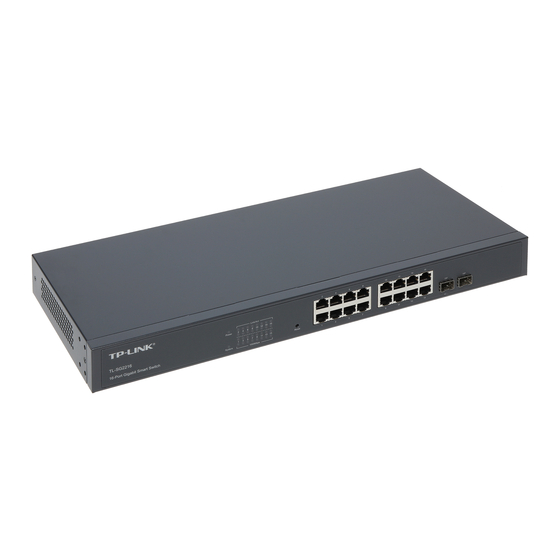
+ Supports Telnet, CLI, SNMP v1/v2c/v3, RMON and web access. + Port Mirroring enables monitoring selected ingress/egress traffic. 2.3 Appearance Description 2.3.1 Front Panel The front panel of TL-SG2216 is shown as Figure 2-1. Figure 2-1 Front Panel of TL-SG2216... - Page 15 10/100/1000Mbps Ports: Designed to connect to the device with a bandwidth of 10Mbps, 100Mbps or 1000Mbps. Each has a corresponding 1000Mbps LED and link/Act LED. SFP Ports: Designed to install the SFP module. TL-SG2216/TL-SG2424/TL-SG2424P switch features some SFP transceiver slots that are shared with the associated RJ45 ports. The associated two ports are referred to as “combo”...
- Page 16 Name Status Indication The switch is working abnormally. System Flashing The switch is working normally. The switch is working abnormally. A 1000Mbps device is connected to the corresponding port. 1000Mbps A 10/100Mbps device or no device is connected to the corresponding port.
-
Page 17: Rear Panel
No device is connected to the corresponding port. 2.3.2 Rear Panel The rear panel of TL-SG2216/TL-SG2424/TL-SG2424P/TL-SG2452 features a power socket and a Grounding Terminal (marked with ), here we take TL-SG2424 for example. Figure 2-5 Rear Panel of the switch ... - Page 18 AC Power Socket: Connect the female connector of the power cord here, and the male connector to the AC power outlet. Please make sure the voltage of the power supply meets the requirement of the input voltage (100-240V~ 50/60Hz 0.6A for TL-SG2216/TL-SG2424, 100-240V~ 50/60Hz 3.5A for TL-SG2424P and100-240V~ 50/60Hz 1.0A for TL-SG2452).
-
Page 19: Chapter 3 Login To The Switch
Chapter 3 Login to the Switch 3.1 Login 1) To access the configuration utility, open a web-browser and type in the default address http://192.168.0.1 in the address field of the browser, then press the Enter key. Figure 3-1 Web-browser Tips: To log in to the switch, the IP address of your PC should be set in the same subnet addresses of the switch. - Page 20 Figure 3-3 Main Setup-Menu Note: Clicking Apply can only make the new configurations effective before the switch is rebooted. If you want to keep the configurations effective even the switch is rebooted, please click Save Config. You are suggested to click Save Config before cutting off the power or rebooting the switch to avoid losing the new configurations.
-
Page 21: Chapter 4 System
Chapter 4 System The System module is mainly for system configuration of the switch, including four submenus: System Info, User Management, System Tools and Access Security. 4.1 System Info The System Info, mainly for basic properties configuration, can be implemented on System Summary, Device Description, System Time, Daylight Saving Time and System IP pages. -
Page 22: Device Description
When the cursor moves on the port, the detailed information of the port will be displayed. Figure 4-2 Port Information Port Info Port: Displays the port number of the switch. Type: Displays the type of the port. Rate: Displays the maximum transmission rate of the port. Status: Displays the connection status of the port. -
Page 23: System Time
Figure 4-4 Device Description The following entries are displayed on this screen: Device Description Device Name: Enter the name of the switch. Device Location: Enter the location of the switch. System Contact: Enter your contact information. 4.1.3 System Time System Time is the time displayed while the switch is running. -
Page 24: Daylight Saving Time
Time Config Manual: When this option is selected, you can set the date and time manually. Get Time from NTP When this option is selected, you can configure the time zone Server: and the IP Address for the NTP Server. The switch will get UTC automatically if it has connected to a NTP Server. -
Page 25: System Ip
Predefined Mode: Select a predefined DST configuration. USA: Second Sunday in March, 02:00 ~ First Sunday in November, 02:00. Australia: First Sunday in October, 02:00 ~ First Sunday in April, 03:00. Europe: Last Sunday in March, 01:00 ~ Last Sunday in ... -
Page 26: User Management
The following entries are displayed on this screen: IP Config MAC Address: Displays MAC Address of the switch. IP Address Mode: Select the mode to obtain IP Address for the switch. Static IP: When this option is selected, you should enter IP ... -
Page 27: User Config
Figure 4-8 User Table 4.2.2 User Config On this page you can configure the access level of the user to log on to the Web management page. The switch provides two access levels: Guest and Admin. The guest only can view the settings without the right to configure the switch;... -
Page 28: System Tools
User Table Select: Select the desired entry to delete the corresponding user information. It is multi-optional. The current user information can’t be deleted. User Name, Displays the current user ID, user name, access level and user Access Level and status. -
Page 29: Config Backup
After being restored, the current settings of the switch will be lost. Wrong uploaded configuration file may cause the switch unmanaged. 4.3.2 Config Backup On this page you can download the current configuration and save it as a file to your computer for your future configuration restore. -
Page 30: System Reboot
Note: Don’t interrupt the upgrade. Please select the proper software version matching with your hardware to upgrade. To avoid damage, please don't turn off the device while upgrading. After upgrading, the device will reboot automatically. You are suggested to backup the configuration before upgrading. 4.3.4 System Reboot On this page you can reboot the switch and return to the login page. -
Page 31: Access Control
4.4.1 Access Control On this page you can control the users logging on to the Web management page to enhance the configuration management security. The definitions of Admin and Guest refer to 4.2 User Management. Choose the menu System→Access Security→Access Control to load the following page. Figure 4-15 Access Control The following entries are displayed on this screen: Access Control Config... -
Page 32: Ssl Config
Port: The field can be available for configuration only when Port-based mode is selected. Only the users connected to these ports you set here are allowed for login. Session Config Session Timeout: If you do nothing with the Web management page within the timeout time, the system will log out automatically. -
Page 33: Ssh Config
Figure 4-16 SSL Config The following entries are displayed on this screen Global Config SSL: Select Enable/Disable the SSL function on the switch. Certificate Download Certificate File: Select the desired certificate to download to the switch. The certificate must be BASE64 encoded. Key Download ... - Page 34 Comprising server and client, SSH has two versions, V1 and V2 which are not compatible with each other. In the communication, SSH server and client can auto-negotiate the SSH version and the encryption algorithm. After getting a successful negotiation, the client sends authentication request to the server for login, and then the two can communicate with each other after successful authentication.
- Page 35 Key File: Select the desired key file to download. Download: Click the Download button to download the desired key file to the switch. Note: Please ensure the key length of the downloaded file is in the range of 256 to 3072 bits. After the Key File is downloaded, the user’s original key of the same type will be replaced.
- Page 36 Application Example 2 for SSH: Network Requirements 1. Log on to the switch via password authentication using SSH and the SSH function is enabled on the switch. 2. PuTTY client software is recommended. Configuration Procedure 1. Select the key type and key length, and generate SSH key. Note: 1.
- Page 37 3. On the Web management page of the switch, download the public key file saved in the computer to the switch. Note: 1. The key type should accord with the type of the key file. 2. The SSH key downloading can not be interrupted. 4.
- Page 38 5. After the public key and private key are downloaded, please log on to the interface of PuTTY and enter the IP address for login. After successful authentication, please enter the login user name. If you log on to the switch without entering password, it indicates that the key has been successfully downloaded.
-
Page 39: Chapter 5 Switching
Chapter 5 Switching Switching module is used to configure the basic functions of the switch, including five submenus: Port, LAG, Traffic Monitor, MAC Address and DHCP Filtering. 5.1 Port The Port function, allowing you to configure the basic features for the port, is implemented on the Port Config, Port Mirror, Port Security , Port Isolation and Loopback Detection pages. -
Page 40: Port Mirror
Description: Give a description to the port for identification. Status: Allows you to Enable/Disable the port. When Enable is selected, the port can forward the packets normally. Speed and Duplex: Select the Speed and Duplex mode for the port. The device connected to the switch should be in the same Speed and Duplex mode with the switch. - Page 41 The following entries are displayed on this screen. Mirror Group List Group: Displays the mirror group number. Mirroring: Displays the mirroring port number. Mode: Displays the mirror mode. The value will be "Ingress" or "Egress". Mirrored Port: Displays the mirrored ports. Operation: Click Edit to configure the mirror group.
-
Page 42: Port Security
Mirrored Port Port Select: Click the Select button to quick-select the corresponding port based on the port number you entered. Select: Select the desired port as a mirrored port. It is multi-optional. Port: Displays the port number. Ingress: Select Enable/Disable the Ingress feature. When the Ingress is enabled, the incoming packets received by the mirrored port will be copied to the mirroring port. - Page 43 Figure 5-4 Port Security The following entries are displayed on this screen: Port Security Select: Select the desired port for Port Security configuration. It is multi-optional. Port: Displays the port number. Max Learned MAC: Specify the maximum number of MAC addresses that can be learned on the port.
-
Page 44: Port Isolation
5.1.4 Port Isolation Port Isolation provides a method of restricting traffic flow to improve the network security by forbidding the port to forward packets to the ports that are not on its forward portlist. Choose the menu Switching→Port→Port Isolation to load the following page. Figure 5-5 Port Isolation The following entries are displayed on this screen: Port Isolation Config... - Page 45 Choose the menu Switching→Port→Loopback Detection to load the following page. Figure 5-6 Loopback Detection Config The following entries are displayed on this screen Port Config Port Select: Click the Select button to quick-select the corresponding port based on the port number you entered. Select: Select the desired port for Loopback Detection configuration.
-
Page 46: Lag
Loop Status: Displays the port status whether a loopback is detected. Block Status: Displays the port status about block or unblock. LAG: Displays the LAG number the port belongs to. Manual Recover: Manually remove the block status of selected ports. Note: Recovery Mode is not selectable when Alert is chosen in Operation Mode. - Page 47 Figure 5-7 LAG Table The following entries are displayed on this screen: Global Config Hash Algorithm: Select the applied scope of Aggregate Arithmetic, which results in choosing a port to transfer the packets. SRC MAC + DST MAC: When this option is selected, the Aggregate Arithmetic will apply to the source and destination MAC addresses of the packets.
-
Page 48: Static Lag
Figure 5-8 Detailed Information 5.2.2 Static LAG On this page, you can manually configure the LAG. Choose the menu Switching→LAG→Static LAG to load the following page. Figure 5-9 Manually Config The following entries are displayed on this screen: LAG Config ... -
Page 49: Lacp Config
Tips: The LAG can be deleted by clearing its all member ports. A port can only be added to a LAG. If a port is the member of a LAG, the port number will be displayed in gray and can not be selected. 5.2.3 LACP Config LACP (Link Aggregation Control Protocol) is defined in IEEE802.3ad and enables the dynamic link aggregation and disaggregation by exchanging LACP packets with its partner. -
Page 50: Traffic Monitor
The following entries are displayed on this screen Global Config System Priority: Specify the system priority for the switch. The system priority and MAC address constitute the system identification (ID). A lower system priority value indicates a higher system priority. When exchanging information between systems, the system with higher priority determines which link aggregation a link belongs to, and the system with lower priority adds the proper links to the link aggregation... - Page 51 Figure 5-11 Traffic Summary The following entries are displayed on this screen: Auto Refresh Auto Refresh: Allows you to Enable/Disable refreshing the Traffic Summary automatically. Refresh Rate: Enter a value in seconds to specify the refresh interval. Traffic Summary ...
-
Page 52: Traffic Statistics
5.3.2 Traffic Statistics Traffic Statistics screen displays the detailed traffic information of each port, which facilitates you to monitor the traffic and locate faults promptly. Choose the menu Switching→Traffic Monitor→Traffic Statistics to load the following page. Figure 5-12 Traffic Statistics The following entries are displayed on this screen: Auto Refresh ... -
Page 53: Mac Address
Alignment Errors: For TL-SG2216/TL-SG2424/TL-SG2424P: Displays the number of the received packets that have a bad Frame Check Sequence (FCS) with a non-integral octet (Alignment Error) and have a bad FCS with an integral octet (CRC Error). The length of the packet is between 64 bytes and 1518 bytes. -
Page 54: Address Table
Being kept after Relationship between the reboot bound MAC address and Configuration Type Aging out the port (if the configuration is saved) Dynamic Automatically The bound MAC address can be learned by the other Address Table learning ports in the same VLAN. Filtering Manually Address Table... -
Page 55: Static Address
Filtering: This option allows the address table to display the filtering address entries only. Address Table MAC Address: Displays the MAC address learned by the switch. VLAN ID: Displays the corresponding VLAN ID of the MAC address. Port: Displays the corresponding Port number of the MAC address. -
Page 56: Dynamic Address
Search Option: Select a Search Option from the pull-down list and click the Search button to find your desired entry in the Static Address Table. MAC: Enter the MAC address of your desired entry. VLAN ID: Enter the VLAN ID number of your desired entry. ... - Page 57 Figure 5-15 Dynamic Address The following entries are displayed on this screen: Aging Config Auto Aging: Allows you to Enable/Disable the Auto Aging feature. Aging Time: Enter the Aging Time for the dynamic address. Search Option Search Option: Select a Search Option from the pull-down list and click the Search button to find your desired entry in the Dynamic Address Table.
-
Page 58: Filtering Address
Tips: Setting aging time properly helps implement effective MAC address aging. The aging time that is too long or too short results decreases the performance of the switch. If the aging time is too long, excessive invalid MAC address entries maintained by the switch may fill up the MAC address table. This prevents the MAC address table from updating with network changes in time. -
Page 59: Dhcp Filtering
Filtering Address Table Select: Select the entry to delete the corresponding filtering address. It is multi-optional. MAC Address: Displays the filtering MAC Address. VLAN ID: Displays the corresponding VLAN ID. Port: Here the symbol “--” indicates no specified port. Type: Displays the Type of the MAC address. - Page 60 Figure 5-17 Network diagram of DHCP For different DHCP clients, DHCP server provides three IP address assigning methods: Manually assign the IP address: Allows the administrator to bind the static IP address to a specific client (e.g.: WWW Server) via the DHCP server. Automatically assign the IP address: DHCP server assigns the IP address without an expiry time limitation to the clients.
- Page 61 addresses and replies to the client with DHCP-OFFER packet carrying the IP address and other information. (3) DHCP-REQUEST Stage: In the situation that there are several DHCP servers sending the DHCP-OFFER packets, the client will only respond to the first received DHCP-OFFER packet and broadcast the DHCP-REQUEST packet which includes the assigned IP address of the DHCP-OFFER packet.
- Page 62 the network from the DHCP Server Cheating Attack by discarding the DHCP packets on the distrusted port, so as to enhance the network security. Choose the menu Switching → DHCP Filtering to load the following page. Figure 5-20 DHCP Filtering The following entries are displayed on this screen DHCP Filtering ...
-
Page 63: Chapter 6 Vlan
Chapter 6 VLAN The traditional Ethernet is a data network communication technology based on CSMA/CD (Carrier Sense Multiple Access/Collision Detect) via shared communication medium. Through the traditional Ethernet, the overfull hosts in LAN will result in serious collision, flooding broadcasts, poor performance or even breakdown of the Internet. -
Page 64: Q Vlan
6.1 802.1Q VLAN VLAN tags in the packets are necessary for the switch to identify packets of different VLANs. The switch works at the data link layer in OSI model and it can identify the data link layer encapsulation of the packet only, so you can add the VLAN tag field into the data link layer encapsulation for identification. -
Page 65: Vlan Config
PVID PVID (Port VLAN ID) is the default VID of the port. When the switch receives an un-VLAN-tagged packet, it will add a VLAN tag to the packet according to the PVID of its received port and forward the packets. When creating VLANs, the PVID of each port, indicating the default VLAN to which the port belongs, is an important parameter with the following two purposes: (1)... - Page 66 Figure 6-3 VLAN Table To ensure the normal communication of the factory switch, the default VLAN of all ports is set to VLAN1. The following entries are displayed on this screen: VLAN Create Enter the VLAN ID you want to create. It ranges from 2 to 4094. VLAN ID:...
-
Page 67: Application Example For 802.1Q Vlan
Port: Displays the port number. Untagged: The port will be an untagged member of the specific VLAN if you select it. Tagged: The port will be an tagged member of the specific VLAN if you select it. NotMember: The port will not be a member of the specific VLAN if you select it. PVID: Here you can change the PVID of the specific port. - Page 68 Configure Switch B Step Operation Description Configure Required. On VLAN→802.1Q VLAN→VLAN Config page, configure Link Type of the the link type of Port 7, Port 6 and Port 8 as Untagged, Tagged and ports Untagged respectively. Create VLAN10 Required. On VLAN→802.1Q VLAN→VLAN Config page, create a VLAN with its VLAN ID as 10, owning Port 6 and Port 8.
-
Page 69: Chapter 7 Spanning Tree
Chapter 7 Spanning Tree STP (Spanning Tree Protocol), subject to IEEE 802.1D standard, is to disbranch a ring network in the Data Link layer in a local network. Devices running STP discover loops in the network and block ports by exchanging information, in that way, a ring network can be disbranched to form a tree-topological ring-free network to prevent packets from being duplicated and forwarded endlessly in the network. - Page 70 Figure 7-1 Basic STP diagram STP Timers Hello Time: Hello Time ranges from 1 to 10 seconds. It specifies the interval to send BPDU packets. It is used to test the links. Max. Age: Max. Age ranges from 6 to 40 seconds. It specifies the maximum time the switch can wait without receiving a BPDU before attempting to reconfigure.
- Page 71 Comparing BPDUs Each switch sends out configuration BPDUs and receives a configuration BPDU on one of its ports from another switch. The following table shows the comparing operations. Step Operation If the priority of the BPDU received on the port is lower than that of the BPDU if of the port itself, the switch discards the BPDU and does not change the BPDU of the port.
- Page 72 stops forwarding data and the designated port of the upstream switch begins to forward data. The condition for the designated port to transit its port state rapidly: The designated port is an edge port or connecting to a point-to-point link. If the designated port is an edge port, it can directly transit to forwarding state;...
- Page 73 Figure 7-2 Basic MSTP diagram MSTP MSTP divides a network into several MST regions. The CST is generated between these MST regions, and multiple spanning trees can be generated in each MST region. Each spanning tree is called an instance. As well as STP, MSTP uses BPDUs to generate spanning tree. The only difference is that the BPDU for MSTP carries the MSTP configuration information on the switches.
-
Page 74: Stp Config
Figure 7-3 Port roles The Spanning Tree module is mainly for spanning tree configuration of the switch, including four submenus: STP Config, Port Config, MSTP Instance and STP Security. 7.1 STP Config The STP Config function, for global configuration of spanning trees on the switch, can be implemented on STP Config and STP Summary pages. - Page 75 The following entries are displayed on this screen: Global Config STP: Select Enable/Disable STP function globally on the switch. Version: Select the desired STP version on the switch. STP: Spanning Tree Protocol. RSTP: Rapid Spanning Tree Protocol. ...
-
Page 76: Stp Summary
7.1.2 STP Summary On this page you can view the related parameters for Spanning Tree function. Choose the menu Spanning Tree→STP Config→STP Summary to load the following page. Figure 7-5 STP Summary 7.2 Port Config On this page you can configure the parameters of the ports for CIST Choose the menu Spanning Tree→Port Config to load the following page. - Page 77 Figure 7-6 Port Config The following entries are displayed on this screen: Port Config Port Select: Click the Select button to quick-select the corresponding port based on the port number you entered. Select: Select the desired port for STP configuration. It is multi-optional. Port: Displays the port number of the switch.
-
Page 78: Mstp Instance
Port Role: Displays the role of the port played in the STP Instance. Root Port: Indicates the port that has the lowest path cost from this bridge to the Root Bridge and forwards packets to the root. Designated Port: Indicates the port that forwards packets to a downstream network segment or switch. -
Page 79: Instance Config
Figure 7-7 Region Config The following entries are displayed on this screen: Region Config Region Name: Create a name for MST region identification using up to 32 characters. Revision: Enter the revision from 0 to 65535 for MST region identification. 7.3.2 Instance Config Instance Configuration, a property of MST region, is used to describe the VLAN to Instance mapping configuration. -
Page 80: Instance Port Config
The following entries are displayed on this screen: Instance Table Instance ID Select: Click the Select button to quick-select the corresponding Instance ID based on the ID number you entered. Select: Select the desired Instance ID for configuration. It is multi-optional. Instance: Displays Instance ID of the switch. - Page 81 Figure 7-9 Instance Port Config The following entries are displayed on this screen: Port Config Instance ID: Select the desired instance ID for its port configuration. Port Select: Click the Select button to quick-select the corresponding port based on the port number you entered. Select: Select the desired port to specify its priority and path cost.
-
Page 82: Stp Security
Step Operation Description Make clear roles the switches Preparation. play spanning tree instances: root bridge designated bridge Globally configure MSTP Required. Enable Spanning Tree function on the switch parameters configure MSTP parameters Spanning Tree→STP Config→STP Config page. Configure MSTP parameters Required. - Page 83 To avoid this, MSTP provides root protect function. Ports with this function enabled can only be set as designated ports in all spanning tree instances. When a port of this type receives BDPU packets with higher priority, it transits its state to blocking state and stops forwarding packets (as if it is disconnected from the link).
-
Page 84: Tc Protect
Figure 7-10 Port Protect The following entries are displayed on this screen: Port Protect Port Select: Click the Select button to quick-select the corresponding port based on the port number you entered. Select: Select the desired port for port protect configuration. It is multi-optional. -
Page 85: Application Example For Stp Function
Choose the menu Spanning Tree→STP Security→TC Protect to load the following page. Figure 7-11 TC Protect The following entries are displayed on this screen: TC Protect TC Threshold: Enter a number from 1 to 100. It is the maximum number of the TC-BPDUs received by the switch in a TC Protect Cycle. - Page 86 Configuration Procedure Configure Switch A: Step Operation Description Configure ports On VLAN→802.1Q VLAN page, configure the link type of the related ports as Tagged, and add the ports to VLAN101-VLAN106. The detailed instructions can be found in the section 802.1Q VLAN.
- Page 87 Configure Switch C: Step Operation Description Configure ports On VLAN→802.1Q VLAN page, configure the link type of the related ports as Tagged, and add the ports to VLAN101-VLAN106. The detailed instructions can be found in the section 802.1Q VLAN. Enable STP function On Spanning Tree→STP Config→STP Config page, enable STP function and select MSTP version.
- Page 88 The topology diagram of the two instances after the topology is stable For Instance 1 (VLAN101, 103 and 105), the red paths in the following figure are connected links; the gray paths are the blocked links. For Instance 2 (VLAN102, 104 and 106), the blue paths in the following figure are connected ...
-
Page 89: Chapter 8 Multicast
Chapter 8 Multicast Multicast Overview In the network, packets are sent in three modes: unicast, broadcast and multicast. In unicast, the source server sends separate copy information to each receiver. When a large number of users require this information, the server must send many pieces of information with the same content to the users. - Page 90 4. Real time is highly demanded and certain packets drop is allowed. Multicast Address 1. Multicast IP Address: As specified by IANA (Internet Assigned Numbers Authority), Class D IP addresses are used as destination addresses of multicast packets. The multicast IP addresses range from 224.0.0.0~239.255.255.255.
-
Page 91: Igmp Snooping
VLAN ID Multicast IP Port Figure 8-3 Multicast Address Table IGMP Snooping In the network, the hosts apply to the near router for joining (leaving) a multicast group by sending IGMP (Internet Group Management Protocol) messages. When the up-stream device forwards down the multicast data, the switch is responsible for sending them to the hosts. -
Page 92: Snooping Config
it will be added to the multicast address table with its member port time specified; if the receiving port is already a member port, its member port time will be directly reset. 3. IGMP Leave Message The host, running IGMPv1, does not send IGMP leave message when leaving a multicast group, as a result, the switch can not get the leave information of the host momentarily. -
Page 93: Port Config
Figure 8-4 Basic Config The following entries are displayed on this screen: Global Config IGMP Snooping: Select Enable/Disable IGMP Snooping function globally on the switch. Unknown Multicast: Select the operation for the switch to process unknown multicast, Forward or Discard. IGMP Snooping Status ... -
Page 94: Vlan Config
Figure 8-5 Port Config The following entries are displayed on this screen: Port Config Port Select: Click the Select button to quick-select the corresponding port based on the port number you entered. Select: Select the desired port for IGMP Snooping feature configuration. It is multi-optional. - Page 95 Figure 8-6 VLAN Config The following entries are displayed on this screen: VLAN Config VLAN ID: Enter the VLAN ID to enable IGMP Snooping for the desired VLAN. Router Port Time: Specify the aging time of the router port. Within this time, if the switch doesn’t receive IGMP query message from the router port, it will consider this port is not a router port any more.
-
Page 96: Multicast Vlan
Router Port: Displays the router port of the VLAN. Note: The settings here will be invalid when multicast VLAN is enabled Configuration procedure: Step Operation Description Enable IGMP Snooping Required. Enable IGMP Snooping globally on the switch function port Multicast→IGMP Snooping→Snooping Config and Port Config page. - Page 97 The following entries are displayed on this screen: Multicast VLAN Multicast VLAN: Select Enable/Disable Multicast VLAN feature. VLAN ID: Enter the VLAN ID of the multicast VLAN. Router Port Time: Specify the aging time of the router port. Within this time, if the switch doesn’t receive IGMP query message from the router port, it will consider this port is not a router port any more.
- Page 98 Application Example for Multicast VLAN: Network Requirements Multicast source sends multicast streams via the router, and the streams are transmitted to user A and user B through the switch. Router: Its WAN port is connected to the multicast source; its LAN port is connected to the switch. The multicast packets are transmitted in VLAN3.
-
Page 99: Multicast Ip
Network Diagram Configuration Procedure Step Operation Description Create VLANs Create three VLANs with the VLAN ID 3, 4 and 5 respectively, and specify the description of VLAN3 as Multicast VLAN on VLAN→802.1Q VLAN page. Configure ports On VLAN→802.1Q VLAN function pages. For port 3, configure its link type as Tagged, and add it to VLAN3, VLAN4 and VLAN5. -
Page 100: Multicast Ip Table
8.2.1 Multicast IP Table On this page you can view the multicast IP table on the switch. Choose the menu Multicast→Multicast IP→Multicast IP Table to load the following page. Figure 8-8 Multicast IP Table The following entries are displayed on this screen: Search Option ... -
Page 101: Multicast Filter
Figure 8-9 Static Multicast IP Table The following entries are displayed on this screen: Create Static Multicast Multicast IP: Enter static multicast IP address. VLAN ID: Enter the VLAN ID of the multicast IP. Forward Port: Enter the forward port of the multicast group. Search Option ... -
Page 102: Ip-Range
port. If the port can be added to the multicast group, it will be added to the multicast address table; if the port can not be added to the multicast group, the switch will drop the IGMP report message. In that way, the multicast streams will not be transmitted to this port, which allows you to control hosts joining the multicast group. -
Page 103: Configuration Procedure
Figure 8-11 Port Filter The following entries are displayed on this screen: Port Filter Config Port Select: Click the Select button to quick-select the corresponding port based on the port number you entered. Select: Select the desired port for multicast filtering. It is multi-optional. Port: Displays the port number. -
Page 104: Packet Statistics
Step Operation Description Configure IP-Range Required. Configure IP-Range filtered Multicast→Multicast Filter→IP-Range page. Configure multicast filter Optional. Configure multicast filter rules for ports on rules for ports Multicast→Multicast Filter→Port Filter page. 8.4 Packet Statistics On this page you can view the multicast data traffic on each port of the switch, which facilitates you to monitor the IGMP messages in the network. - Page 105 Query Packet: Displays the number of query packets the port received. Report Packet (V1): Displays the number of IGMPv1 report packets the port received. Report Packet (V2): Displays the number of IGMPv2 report packets the port received. Report Packet (V3): Displays the number of IGMPv3 report packets the port received.
-
Page 106: Chapter 9 Qos
Chapter 9 QoS QoS (Quality of Service) functions to provide different quality of service for various network applications and requirements and optimize the bandwidth resource distribution so as to provide a network service experience of a better quality. This switch classifies the ingress packets, maps the packets to different priority queues and then forwards the packets according to specified scheduling algorithms to implement QoS function. - Page 107 Figure 9-2 802.1Q frame As shown in the figure above, each 802.1Q Tag has a Pri field, comprising 3 bits. The 3-bit priority field is 802.1p priority in the range of 0 to 7. 802.1P priority determines the priority of the packets based on the Pri value.
- Page 108 Figure 9-4 SP-Mode WRR-Mode: Weight Round Robin Mode. In this mode, packets in all the queues are sent in order based on the weight value for each queue and every queue can be assured of a certain service time. The weight value indicates the occupied proportion of the resource. WRR queue overcomes the disadvantage of SP queue that the packets in the queues with lower priority can not get service for a long time.
-
Page 109: Diffserv
Equ-Mode: Equal-Mode. In this mode, all the queues occupy the bandwidth equally. The weight value ratio of all the queues is 1:1:1:1. The QoS module is mainly for traffic control and priority configuration, including three submenus: DiffServ Bandwidth Control and Voice VLAN. 9.1 DiffServ This switch classifies the ingress packets, maps the packets to different priority queues and then forwards the packets according to specified scheduling algorithms to implement QoS function. -
Page 110: Dscp Priority
Step Operation Description Select the port priority Required. On QoS→DiffServ→Port Priority page, configure the port priority. Configure mapping Required. On QoS→DiffServ→802.1P Priority page, relation between the 802.1P configure the mapping relation between the 802.1P priority and TC priority and TC. Select a schedule mode Required. -
Page 111: P/Cos Mapping
DSCP: Indicates the priority determined by the DS region of IP datagram. It ranges from 0 to 63. Priority: Indicates the 802.1P priority the packets with tag are mapped to. The priorities are labeled as CoS0 ~ CoS7. Configuration Procedure: Step Operation Description Configure... -
Page 112: Schedule Mode
Queue TC-id: Indicates the priority level of egress queue the packets with tag and CoS-id are mapped to. The priority levels of egress queue are labeled as TC0, TC1, TC2 and TC3. Configuration Procedure: Step Operation Description Configure mapping Required. On QoS→DiffServ→802.1P/CoS mapping relation between the 802.1P page, configure the mapping relation between the priority Tag/CoS and the TC... -
Page 113: Bandwidth Control
Equ-Mode: Equal-Mode. In this mode, all the queues occupy the bandwidth equally. The weight value ratio of all the queues is 1:1:1:1. 9.2 Bandwidth Control Bandwidth function, allowing you to control the traffic rate and broadcast flow on each port to ensure network in working order, can be implemented on Rate Limit and Storm Control pages. -
Page 114: Storm Control
Ingress Rate (bps): Configure the bandwidth for receiving packets on the port. You can select a rate from the dropdown list or select "Manual" to set Ingress rate, the system will automatically select integral multiple of 64Kbps that closest to the rate you entered as the real Ingress rate. Egress Rate(bps): Configure the bandwidth for sending packets on the port. -
Page 115: Voice Vlan
The following entries are displayed on this screen: Storm Control Config Port Select: Click the Select button to quick-select the corresponding port based on the port number you entered. Select: Select the desired port for Storm Control configuration. It is multi-optional. - Page 116 Number OUI Address Vendor 00-01-e3-00-00-00 Siemens phone 00-03-6b-00-00-00 Cisco phone 00-04-0d-00-00-00 Avaya phone 00-60-b9-00-00-00 Philips/NEC phone 00-d0-1e-00-00-00 Pingtel phone 00-e0-75-00-00-00 Polycom phone 00-e0-bb-00-00-00 3com phone Table 9-1 OUI addresses on the switch Port Voice VLAN Mode A voice VLAN can operate in two modes: automatic mode and manual mode. Automatic Mode: In this mode, the switch automatically adds a port which receives voice packets to voice VLAN and determines the priority of the packets through learning the source MAC of the UNTAG packets sent from IP phone when it is powered on.
-
Page 117: Global Config
Security Mode of Voice VLAN When voice VLAN is enabled for a port, you can configure its security mode to filter data stream. If security mode is enabled, the port just forwards voice packets, and discards other packets whose source MAC addresses do not match OUI addresses. -
Page 118: Port Config
VLAN ID: Enter the VLAN ID of the voice VLAN. Aging Time: Specifies the living time of the member port in auto mode after the OUI address is aging out. Priority: Select the priority of the port when sending voice data. 9.3.2 Port Config Before the voice VLAN function is enabled, the parameters of the ports in the voice VLAN should be configured on this page. -
Page 119: Oui Config
Port Mode: Select the mode for the port to join the voice VLAN. Auto: In this mode, the switch automatically adds a port to the voice VLAN or removes a port from the voice VLAN by checking whether the port receives voice data or not. ... - Page 120 OUI: Displays the OUI address of the voice device. Mask: Displays the OUI address mask of the voice device. Description: Displays the description of the OUI. Configuration Procedure of Voice VLAN: Step Operation Description Configure the link type of Required. On VLAN→802.1Q VLAN→VLAN Config the port page, configure the link type of ports of the voice device.
-
Page 121: Chapter 10 Acl
Chapter 10 ACL 10.1 ACL Config An ACL may contain a number of rules, and each rule specifies a different package range. Packets are matched in match order. Once a rule is matched, the switch processes the matched packets taking the operation specified in the rule without considering the other rules, which can enhance the performance of the switch. -
Page 122: Mac Acl
Figure 10-2 ACL Create The following entries are displayed on this screen: Create ACL ACL ID: Enter ACL ID of the ACL you want to create. Rule Order: User Config order is set to be match order in this ACL. 10.1.3 MAC ACL MAC ACLs analyze and process packets based on a series of match conditions, which can be the source MAC addresses and destination MAC addresses carried in the packets. -
Page 123: Standard-Ip Acl
D-MAC: Enter the destination MAC address contained in the rule. MASK: Enter MAC address mask. If it is set to 1, it must strictly match the address. 10.1.4 Standard-IP ACL Standard-IP ACLs analyze and process data packets based on a series of match conditions, which can be the source IP addresses and destination IP addresses carried in the packets. -
Page 124: Policy Config
Figure 10-5 Create Extend-IP Rule The following entries are displayed on this screen: Create Extend-IP ACL ACL ID: Select the desired Extend-IP ACL for configuration. Rule ID: Enter the rule ID. Operation: Select the operation for the switch to process packets which match the rules. -
Page 125: Policy Summary
10.2.1 Policy Summary On this page, you can view the ACL and the corresponding operations in the policy. Choose the menu ACL→Policy Config→Policy Summary to load the following page. Figure 10-6 Policy Summary The following entries are displayed on this screen: Search Option ... -
Page 126: Action Create
10.2.3 Action Create On this page you can add ACLs for the policy. Choose the menu ACL→Policy Config→Action Create to load the following page. Figure 10-8 Action Create The following entries are displayed on this screen: Create Action Select Policy: Select the name of the policy. -
Page 127: Port Binding
Port: Displays the number of the port bound to the corresponding policy. Direction: Displays the binding direction. Note: For TL-SG2216/TL-SG2424/TL-SG2424P, you can bind one policy to multiple interfaces; but for TL-SG2452, you can bind one policy to only one interface... -
Page 128: Vlan Binding
Required. On ACL→Policy Binding configuration pages, port/VLAN bind the policy to the port/VLAN to make the policy effective on the corresponding port/VLAN. Note: For TL-SG2216/TL-SG2424/TL-SG2424P, you can bind one policy to multiple VLANs; but for TL-SG2452, you can bind one policy to only one VLAN... - Page 129 10.4 Application Example for ACL Network Requirements 1. The manager of the R&D department can access to the forum of the company and the Internet without any forbiddance. The MAC address of the manager is 00-64-A5-5D-12-C3. 2. The staff of the R&D department can not access to the Internet but can visit the forum. 3.
- Page 130 Step Operation Description Configure On ACL→ACL Config→ACL Create page, create ACL 100. requirement On ACL→ACL Config→Standard-IP ACL page, select ACL 100, and 4 create Rule 1, configure operation as Deny, configure S-IP as 10.10.70.1 and mask as 255.255.255.0, configure D-IP as 10.10.50.1 and mask as 255.255.255.0.
-
Page 131: Chapter 11 Poe
Chapter 11 PoE Note: Only TL-SG2424P supports PoE function. PoE (Power over Ethernet) technology describes a system to transmit electrical power along with data to remote devices over standard twisted-pair cable in an Ethernet network. It is especially useful for supplying power to IP telephones, wireless LAN access points, cameras and so on. ... -
Page 132: Poe Config
PoE Config, mainly for PoE attributes configuration, is implemented on PoE Config and PoE Profile pages. 11.1.1 PoE Config On this page, you can configure the parameters to implement PoE function. Choose the menu PoE→PoE Config→PoE Config to load the following page. Figure 11-1 PoE Config The following items are displayed on this screen: Global Config... -
Page 133: Poe Profile
PoE Priority: The priority levels include High, Middle and Low in descending order. When the supply power exceeds the system power limit, the PD linked to the port with lower priority will be disconnected. Power Limit Defines the max power the corresponding port can supply. Class1 (0.1w-30w): represents 4w, Class2 represents 7w, Class3 represents 15.4w and Class4 represents 30w. -
Page 134: Poe Time-Range
PoE Status: Select to the enable/disable PoE feature for the corresponding port. If set enable, the port may supply power to the linked PD (Power Device). PoE Priority: The priority levels include High, Middle and Low in descending order. When the supply power exceeds the system power limit, the PD linked to the port with lower priority will be disconnected. -
Page 135: Poe Time-Range Create
Index: Displays the index of the time-range. Time-Range Name: Displays the name of the time-range. Slice: Displays the time-slice of the time-range. Mode: Displays the mode the time-range adopts. Operation: Click Edit to modify this time-range and click Detail to display the complete information of this time–range. -
Page 136: Poe Holiday Config
End Time: Set the end time of the time-slice. Time-Slice Table Index: Displays the index of the time-slice. Start Time: Displays the start time of the time-slice. End Time: Displays the end time of the time-slice. Delete: Click the Delete button to delete the corresponding time-slice. 11.2.3 PoE Holiday Config Holiday mode is applied as a different secured access control policy from the week mode. - Page 137 End Date: Displays the end date of the holiday. Return to CONTENTS...
-
Page 138: Chapter 12 Snmp
Chapter 12 SNMP SNMP Overview SNMP (Simple Network Management Protocol) has gained the most extensive application on the UDP/IP networks. SNMP provides a management frame to monitor and maintain the network devices. It is used for automatically managing the various network devices no matter the physical differences of the devices. - Page 139 application requirement. SNMP v1: SNMP v1 adopts Community Name authentication. The community name is used to define the relation between SNMP Management Station and SNMP Agent. The SNMP packets failing to pass community name authentication are discarded. The community name can limit access to SNMP Agent from SNMP NMS, functioning as a password.
-
Page 140: Snmp Config
The User configured in a SNMP Group can manage the switch via the client program on management station. The specified User Name and the Auth/Privacy Password are used for SNMP Management Station to access the SNMP Agent, functioning as the password. SNMP module is used to configure the SNMP function of the switch, including three submenus: SNMP Config, Notification and RMON. -
Page 141: Snmp View
12.1.2 SNMP View The OID (Object Identifier) of the SNMP packets is used to describe the managed objects of the switch, and the MIB (Management Information Base) is the set of the OIDs. The SNMP View is created for the SNMP management station to manage MIB objects. Choose the menu SNMP→SNMP Config→SNMP View to load the following page. - Page 142 Figure 12-5 SNMP Group The following entries are displayed on this screen: Group Config Group Name: Enter the SNMP Group name. The Group Name, Security Model and Security Level compose the identifier of the SNMP Group. The Groups with these three items the same are considered to be the same.
-
Page 143: Snmp User
Notify View: Select the View to be the Notify View. The management station can receive trap messages of the assigned SNMP view generated by the switch's SNMP agent. Group Table Select: Select the desired entry to delete the corresponding group. It is multi-optional. - Page 144 User Config User Name: Enter the User Name here. User Type: Select the type for the User. Local User: Indicates that the user is connected to a local SNMP engine. Remote User: Indicates that the user is connected to a remote SNMP engine.
-
Page 145: Snmp Community
12.1.5 SNMP Community SNMP v1 and SNMP v2c adopt community name authentication. The community name can limit access to the SNMP agent from SNMP network management station, functioning as a password. If SNMP v1 or SNMP v2c is employed, you can directly configure the SNMP Community on this page without configuring SNMP Group and User. - Page 146 Configuration Procedure: If SNMPv3 is employed, please take the following steps: Step Operation Description Enable SNMP function globally. Required. On the SNMP→SNMP Config→Global Config page, enable SNMP function globally. Create SNMP View. Required. On the SNMP→SNMP Config→SNMP View page, create SNMP View of the management agent.
-
Page 147: Notification
12.2 Notification With the Notification function enabled, the switch can initiatively report to the management station about the important events that occur on the Views (e.g., the managed device is rebooted), which allows the management station to monitor and process the events in time. The notification information includes the following two types: Trap :... -
Page 148: Rmon
Type: Select the type for the notifications. Trap: Indicates traps are sent. Inform: Indicates informs are sent. The Inform type has a higher security than the Trap type. Retry: Specify the amount of times the switch resends an inform request. -
Page 149: History Control
RMON Group Function History Group After a history group is configured, the switch collects and records network statistics information periodically, based on which the management station can monitor network effectively. Event Group Event Group is used to define RMON events. Alarms occur when an event is detected. -
Page 150: Event Config
Status: Select Enable/Disable the corresponding sampling entry. 12.3.2 Event Config On this page, you can configure the RMON events. Choose the menu SNMP→RMON→Event Config to load the following page. Figure 12-10 Event Config The following entries are displayed on this screen: Event Table ... - Page 151 Figure 12-11 Alarm Config The following entries are displayed on this screen: Alarm Table Select: Select the desired entry for configuration. Index: Displays the index number of the entry. Variable: Select the alarm variables from the pull-down list. Port: Select the port on which the Alarm entry acts.
- Page 152 Interval: Enter the alarm interval time in seconds. Owner: Enter the name of the device or user that defined the entry. Status: Select Enable/Disable the corresponding alarm entry. Note: When alarm variables exceed the Threshold on the same direction continuously for several times, an alarm event will only be generated on the first time, that is, the Rising Alarm and Falling Alarm are triggered alternately for that the alarm following to Rising Alarm is certainly a Falling Alarm and vice versa.
-
Page 153: Chapter 13 Lldp
Chapter 13 LLDP Note: Only TL-SG2424P supports LLDP function. LLDP (Link Layer Discovery Protocol) is a Layer 2 protocol that is used for network devices to advertise their own device information periodically to neighbors on the same IEEE 802 local area network. - Page 154 or to allow the port to both transmit and receive LLDPDUs. Four LLDP admin statuses are supported by each port. Tx&Rx: the port can both transmit and receive LLDPDUs. Rx_Only: the port can receive LLDPDUs only. Tx_Only: the port can transmit LLDPDUs only. ...
- Page 155 The following table shows the details about the currently defined TLVs. TLV type TLV Name Description Usage in LLDPDU End of LLDPDU Mark the end of the TLV sequence in LLDPDUs. Mandatory Any information following an End Of LLDPDU TLV shall be ignored. Chassis ID Identifies the Chassis address of the connected Mandatory...
- Page 156 Note: For detailed introduction of TLV, please refer to IEEE 802.1AB standard and ANSI/TIA-1057. In TP-LINK switch, the following LLDP optional TLVs are supported. Port Description TLV The Port Description TLV allows network management to advertise the IEEE 802 LAN station's port description. System Capabilities TLV The System Capabilities TLV identifies the primary functions of the system and whether or not these primary functions are...
-
Page 157: Basic Config
The LLDP module is mainly for LLDP function configuration of the switch, including three submenus: Basic Config, Device Info, Device Statistics and LLDP-MED. 13.1 Basic Config LLDP is configured on the Global Config and Port Config pages. 13.1.1 Global Config On this page you can configure the LLDP parameters of the device globally. -
Page 158: Port Config
Fast Start Times: When the port's LLDP state transforms from Disable (or Rx_Only) to Tx&Rx (or Tx_Only), the fast start mechanism will be enabled, that is, the transmit interval will be shorten to a second, and several LLDPDUs will be sent out (the number of LLDPDUs equals this parameter). -
Page 159: Device Info
13.2 Device Info You can view the LLDP information of the local device and its neighbors on the Local Info and Neighbor Info pages respectively. 13.2.1 Local Info On this page you can see all ports' configuration and system information. Choose the menu LLDP→Device Info→Local Info to load the following page. -
Page 160: Neighbor Info
Refresh Rate: Specify the auto refresh rate. Local Info Enter the desired port number and click Select to display the information of the corresponding port. 13.2.2 Neighbor Info On this page you can get the information of the neighbors. Choose the menu LLDP→Device Info→Neighbor Info to load the following page. - Page 161 Figure 13-5 LLDP Statistic Information The following entries are displayed on this screen Auto Refresh Auto Refresh: Enable/Disable the auto refresh function. Refresh Rate: Specify the auto refresh rate. Global Statistics Last Update: Displays latest update time of the statistics. Total Inserts: Displays the number of neighbors inserted till last update time.
-
Page 162: Lldp-Med
based on the port number you entered. Port: Displays local device's port number. Transmit Total: Displays the number of LLDPDUs sent by this port. Receive Total: Displays the number of LLDPDUs received by this port. Discards: Displays the number of LLDPDUs discarded by this port. Errors: Displays the number of error LLDPDUs received by this port. -
Page 163: Global Config
Extended Power-Via-MDI TLV The Extended Power-Via-MDI TLV is intended to enable advanced power management between LLDP-MED Endpoint Network Connectivity Devices, allows advertisement of fine grained power requirement details, Endpoint power priority, as well as both Endpoint and Network Connectivity Device power status. Inventory TLV The Inventory TLV set contains seven basic Inventory management TLVs, that is, Hardware Revision TLV, Firmware... - Page 164 Figure 13-7 LLDP-MED Port Configuration The following entries are displayed on this screen LLDP-MED Port Config Port Select: Select the desired port to configure. LLDP-MED Status: Configure the port's LLDP-MED status: Enable: Enable the port's LLDP-MED status, and the port's Admin Status will be changed to Tx&Rx.
-
Page 165: Local Info
Included TLVs Select TLVs to be included in outgoing LLDPDU. Location Identification Parameters Configure the Location Identification TLV's content in outgoing LLDPDU of the port. Emergency Emergency number is Emergency Call Service ELIN identifier, Number: which is used during emergency call setup to a traditional CAMA or ISDN trunk-based PSAP. -
Page 166: Neighbor Info
Figure 13-8 LLDP-MED Local Information The following entries are displayed on this screen Auto Refresh Auto Refresh: Enable/Disable the auto refresh function. Refresh Rate: Specify the auto refresh rate. Local Info Enter the desired port number and click Select to display the information of the corresponding port. - Page 167 Figure 13-9 LLDP-MED Neighbor Information The following entries are displayed on this screen Auto Refresh Auto Refresh: Enable/Disable the auto refresh function. Refresh Rate: Specify the auto refresh rate. Neighbor Info Port Select: Click the Select button to quick-select the corresponding port based on the port number you entered.
-
Page 168: Chapter 14 Maintenance
Chapter 14 Maintenance Maintenance module, assembling the commonly used system tools to manage the switch, provides the convenient method to locate and solve the network problem. (1) System Monitor: Monitor the utilization status of the memory and the CPU of switch. (2)... -
Page 169: Memory Monitor
14.1.2 Memory Monitor Choose the menu Maintenance→System Monitor→Memory Monitor to load the following page. Figure 14-2 Memory Monitor Click the Monitor button to enable the switch to monitor and display its Memory utilization rate every four seconds. 14.2 Log The Log system of switch can record, classify and manage the system information effectively, providing powerful support for network administrator to monitor network operation and diagnose malfunction. -
Page 170: Log Table
The Log function is implemented on the Log Table, Local Log, Remote Log and Backup Log pages. 14.2.1 Log Table The switch supports logs output to two directions, namely, log buffer and log file. The information in log buffer will be lost after the switch is rebooted or powered off whereas the information in log file will be kept effective even the switch is rebooted or powered off. -
Page 171: Local Log
Choose the menu Maintenance→Log→Local Log to load the following page. Figure 14-4 Local Log The following entries are displayed on this screen: Local Log Config Select: Select the desired entry to configure the corresponding local log. Log Buffer: Indicates the RAM for saving system log. The inforamtion in the log buffer is displayed on the Log Table page. -
Page 172: Backup Log
Figure 14-5 Log Host The following entries are displayed on this screen: Log Host Index: Displays the index of the log host. The switch supports 4 log hosts. Host IP: Configure the IP for the log host. UDP Port: Displays the UDP port used for receiving/sending log information. -
Page 173: Device Diagnostics
Backup Log Backup Log: Click the Backup Log button to save the log as a file to your computer. Note: It will take a few minutes to backup the log file. Please wait without any operation. 14.3 Device Diagnostics This switch provides Cable Test and Loopback functions for device diagnose. -
Page 174: Loopback
14.3.2 Loopback Loopback test function, looping the sender and the receiver of the signal, is used to test whether the port of the switch is available as well as to check and analyze the physical connection status of the port to help you locate and solve network malfunctions. Choose the menu Maintenance→Device Diagnostics→Loopback to load the following page. -
Page 175: Tracert
Figure 14-9 Ping The following entries are displayed on this screen: Ping Config Destination IP: Enter the IP address of the destination node for Ping test. Ping Times: Enter the amount of times to send test data during Ping testing. The default value is recommended. - Page 176 Tracert Config Destination IP: Enter the IP address of the destination device. Max Hop: Specify the maximum number of the route hops the test data can pass through. Return to CONTENTS...
-
Page 177: Appendix A: Specifications
Transmission Medium 1000Base-T: 4-pair UTP (≤100m) of Cat. 5, Cat. 5e, Cat.6 or above 1000Base-X: MMF or SMF SFP Module (Optional) For TL-SG2216/TL-SG2424: Power, System,1000Mbps, Link/Act For TL-SG2424P: Power, System, 10/100/1000Mbps Port LED, Speed, PoE, PoE Max For TL-SG2452: PWR, SYS, 10/100/1000Mbps... - Page 178 Return to CONTENTS...
-
Page 179: Appendix B: Configuring The Pcs
Appendix B: Configuring the PCs In this section, we’ll introduce how to install and configure the TCP/IP correctly in Windows 2000. First make sure your Ethernet Adapter is working, refer to the adapter’s manual if necessary. On the Windows taskbar, click the Start button, and then click Control Panel. Click the Network and Internet Connections icon, and then click on the Network Connections tab in the appearing window. - Page 180 The following TCP/IP Properties window will display and the IP Address tab is open on this window by default. Figure B-3 Select Use the following IP address. And the following items will be available. If the switch's IP address is 192.168.0.1, specify IP address as 192.168.0.x (x is from 2 to 254), and the Subnet mask as 255.255.255.0.
-
Page 181: Appendix C: Glossary
Appendix C: Glossary Boot Protocol (BOOTP) BOOTP is used to provide bootup information for network devices, including IP address information, the address of the TFTP server that contains the devices system files, and the name of the boot file. Class of Service (CoS) CoS is supported by prioritizing packets based on the required level of service, and then placing them in the appropriate output queue. - Page 182 Internet Group Management Protocol (IGMP) A protocol through which hosts can register with their local router for multicast services. If there is more than one multicast switch/router on a given subnetwork, one of the devices is made the “querier” and assumes responsibility for keeping track of group membership. IGMP Snooping Listening to IGMP Query and IGMP Report packets transferred between IP Multicast routers and IP Multicast host groups to identify IP Multicast group members.
- Page 183 Remote Authentication Dial-in User Service (RADIUS) RADIUS is a logon authentication protocol that uses software running on a central server to control access to RADIUS-compliant devices on the network. Remote Monitoring (RMON) RMON provides comprehensive network monitoring capabilities. It eliminates the polling required in standard SNMP, and can set alarms on a variety of traffic conditions, including specific error types.
Need help?
Do you have a question about the TL-SG2216 and is the answer not in the manual?
Questions and answers